ESDEP WG 10
COMPOSITE CONSTRUCTION
To explain the behaviour of partial shear connection in composite beams and to present the practical methods used for design at ultimate and serviceability limit states.
Lecture 10.3: Single Span Beams
Lecture 10.4.1: Continuous Beams I
Lecture 10.6.1: Shear Connection I
Lectures 10.5: Design for Serviceability
Lecture 10.6.3: Shear Connection III
Partial shear connection is defined and its advantages when used for beams in buildings, are summarised. The effect of slip at the steel/concrete interface cannot be analysed by means of simplified approaches; for this reason, a clear distinction between ductile and non-ductile connectors is made.
For simply supported beams, a practical method is proposed for partial-interaction design at ultimate limit state, using a reduced plastic moment curve; limitations are placed on this method depending on the degree of connection and connector ductility. Practical formulae are given to check the serviceability limit state (maximum deflection, stresses in extreme fibres, and connector forces), which is important if a low degree of connection is used.
This lecture describes the design of partial shear connection in composite beams. In general "full shear connection" is defined as the least number of connectors for a given beam, loading, and design method, such that the bending resistance of the beam would not be increased if more connectors were provided; otherwise, the shear connection is partial. In practice, partial shear connection is often used in multi-storey, multi-bay buildings for the following reasons:
Accurate models dealing with partial connection are difficult to develop [1, 2]. Therefore, the main objective in this lecture is to present and explain simplified design methods, which are appropriate if an idealisation of the connectors' behaviour with regard to their deformation capacity in slip is accepted. So, in conformity with the classification adopted in Eurocode 4 [3], a clear distinction is made here between ductile and non-ductile connectors. The case of absolutely rigid non-ductile shear connectors is addressed briefly in Section 3; the best solution, in this case, is to design the shear connection by a simple and safe process based on an elastic analysis of the beam, which does not raise theoretical difficulties.
The lecture is devoted principally to the case of ductile shear connectors in simply supported beams. As explained in Section 4, the concept of partial shear connection is relatively easy to apply to simply supported beams because plastic theory may be used for determining the resistance of cross-sections. This ease of application is because, according to the definitions given in Lecture 10.3, critical cross-sections in sagging bending are often in Class 1 (even with thin webs), or at worst in Class 2 (if the plastic neutral axis lies in the steel web). Attention is also drawn to restrictions on the use of partial shear connection, e.g. at ultimate limit state for very long spans, and also at serviceability limit state because of amplification of deflections due to bending.
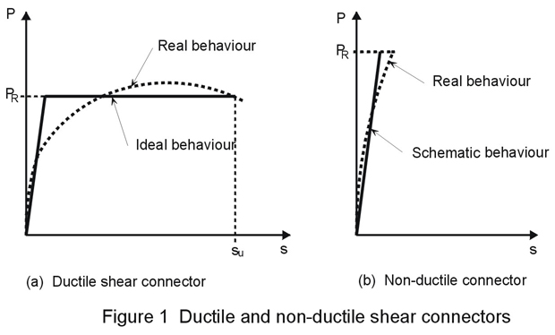
The most important material property of a shear connector is its ductility. According to Eurocode 4 [3], ductile connectors are defined as those having sufficient deformation capacity, in slip, to justify the assumption of perfectly plastic behaviour for the shear connection. When compared to the real load-slip curve for a given connector, this definition determines the values of two relevant properties (see Figure 1a): the shear resistance of the connector, PR, which corresponds to the yield plateau of an equivalent load-slip curve and is often taken as the characteristic resistance of the connector; and the slip capacity of the connector, su, which may be taken as the maximum slip measured at the characteristic load level. It is to be noted that in real applications, the resistance PR should be replaced by the design resistance PRd obtained by dividing PR by an appropriate partial safety factor gV. This factor allows for uncertainties in both the material properties and in the design formula used to calculate the shear resistance. For slip capacity su, Eurocode 4 estimates that a value greater than 6 mm allows shear connectors to be considered as ductile. Experimental tests have shown that this requirement is commonly satisfied by headed studs welded to a steel beam, provided that they have an overall length after welding not less than 4 times the diameter, and their shank diameter lies within the range 16 mm - 22 mm. Moreover, it has been shown that, when the studs are welded through profiled steel sheeting and extend sufficiently above the top of the steel ribs, the slip capacity may become much higher than for solid slabs, with for example, su equal to 10 or 15 mm. This favourable increase in slip capacity is often accompanied by more complicated connector behaviour such as the occurrence of a falling-branch in the load-slip curve, which is difficult to take into account in ordinary design. Other connectors may also exhibit ductile behaviour, e.g. friction grip bolts used with precast solid slabs if detailed appropriately.
Alternatively, absolutely rigid shear connectors, i.e. non-ductile, can be defined as those which fracture when the ultimate load PR of the connector is reached without any significant slip; in this case, the subsequent shear resistance falls suddenly to zero. In practice, a block connector should be so classified because its only slip capacity is due to the concrete compressed just in front of its face. Compared to this type, other connectors such as angles or hoop connectors would seem ductile because of the flexibility and partial ductility of their steel components. Nevertheless, in the absence of an explicit relationship for their load-slip behaviour, and a rigorous calculation of the longitudinal shear along the steel and concrete interface, it is recommended that they are considered as absolutely rigid non-ductile connectors. This is a conservative assumption for shear connection design.
When absolutely rigid, i.e. non-ductile, shear connectors are used in a composite beam under increasing load, the ultimate load is reached as soon as the longitudinal shear force on the most heavily loaded shear connector becomes equal to its shear resistance PRd. Therefore, the optimum design adopts the distribution of the shear connectors which corresponds to the distribution of the longitudinal shear force. No simple application of elastic-plastic analysis is possible here and so elastic analysis only is used to calculate the internal forces in the beam. As, in theory, no slip is possible before failure, there is complete interaction between the concrete slab and the steel member. It is logical, therefore, to determine the longitudinal shear per unit length of interface by means of the familiar elastic beam theory. This theory gives the following formula:
T(x) = V(x) ![]() (1)
(1)
where
V(x) is the shear at cross-section x.
S is the first moment of area taken at the steel-concrete interface.
I is the second moment of area of the whole cross-section.
S and I must, of course, be calculated by replacing the concrete area Ac, by an equivalent steel area equal to Ac/n, where n is the modular ratio:
n = Ea/Ec (2)
In this context, the principle of design for the shear connection is similar for simply supported and continuous beams. Except for specific rules applying near to the end of each span, it is generally accepted that the size and spacing of the connectors may be kept constant over any length l where, under the design load considered, the extreme values of the shear flow T(x) do not exceed its mean value T by more than 10 per cent (some codes adopt 5 per cent). On every such length, the total longitudinal shear force should not exceed the product of the number N of connectors and the design resistance per connector. Therefore, N can be obtained from the following:
N ³ ![]() (3)
(3)
The distribution of shear connectors may be influenced by preloading of the steel beam (propped/unpropped construction), and by internal stresses possibly caused by shrinkage and creep of the concrete. For shrinkage and creep, the calculation of stresses and the longitudinal shear flow T(x) must be based on a larger value of the modular ratio n (for long-term effects, the original ratio is multiplied by a factor of 2 or 3).
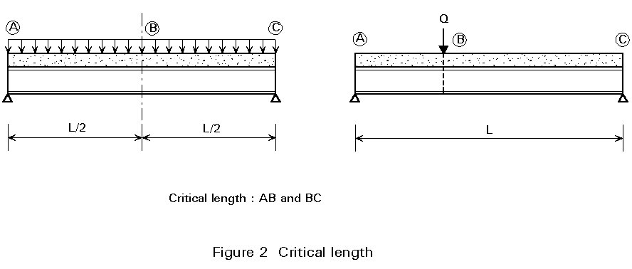
For simplification, only a simply supported beam with constant cross-sections, subject to either a uniformly distributed loading or one concentrated load (but not both), is considered. Two general terms must first be defined:
Considering any critical length of a simply supported beam (see Figure 2), the maximum value of the total longitudinal shear force, Vlf, in the length can be determined by assuming that the plastic resistance moment is reached in the internal critical cross-section. Consequently, Vlf is equal to the lesser plastic axial resistance of either the steel member or the concrete slab in the critical cross-section concerned. As shown in Lecture 10.3, the tension resistance of the steel member is equal to Aa fy/ga and the compressive resistance of the concrete slab is equal to 0,85fck/gc times its area Ac (within the effective width beff). Therefore:
Vlf = lesser value of (Aa fy/ga or 0,85Ac fck/gc) (4)
It should be noted that the small effect of the longitudinal reinforcement in compression is neglected in this derivation.
As each shear connector is able to transfer a force equal to its ultimate resistance PRd (assuming adequate ductility), the required number Nf of connectors to obtain full shear connection for the critical length in question is given by:
Nf = Vlf/PRd (5)
If the number N of shear connectors within the critical length is less than Nf:
N < Nf (6)
the critical length is in partial shear connection and its degree of connection is defined by the ratio N/Nf. Obviously a beam is fully connected only if all its critical lengths are fully connected.
For the purpose of design (assuming ductile connectors are used), it will be sufficient to introduce the concept of a reduced ultimate moment curve, without having to calculate the slip along the steel-concrete interface.
a) Reduced ultimate moment curve
The reduction in the ultimate moment of the internal critical cross-section, due to the reduction in the number of connectors, can be easily calculated. Assuming that each connector develops its design shear resistance, the total longitudinal shear force Vl in each critical length is equal to the sum of the shear resistances of the connectors and also to the maximum compressive force Fu(r) in the slab:
Vl = N PRd = Fu(r) (7)
where N < Nf (see Figure 3). The corresponding depth of the concrete stress block is equal to:
yc = Fu(r)/[0,85fckbeff /gc] £ hc (8)
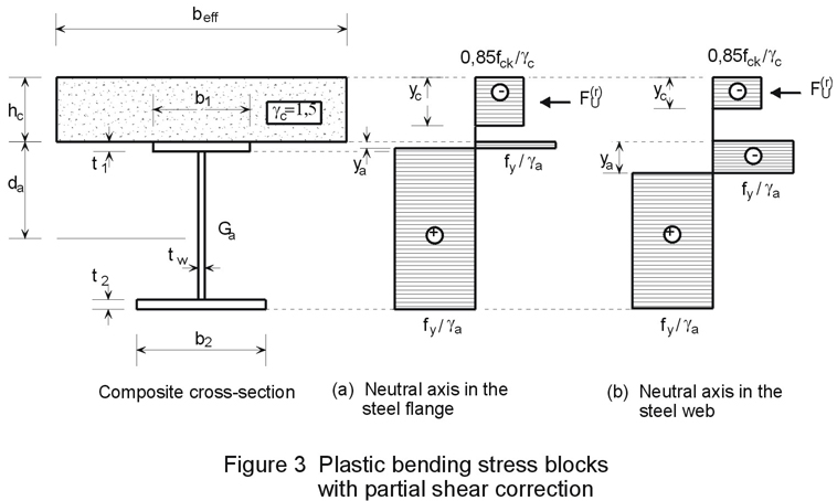
The position of the neutral axis in the steel beam can be determined from equating Fu(r) to the tensile force in the steel beam, and the reduced ultimate moment Mu(r) can be calculated accordingly. The result is (see Figure 3):
ya = [As(fy/ga) - Fu(r)]/[2b1(fy/ga)] with: ya £ t1 (9)
Mu(r) = Fu(r)(hc + da- yc/2) + 2b1ya(fy/ga)(da - ya/2) (10)
ya = {(As + 2t1tw - 2b1t1)(fy/ga) - Fu(r)}/[2tw(fy/ga)] (11)
where
t1 £ ya £ da
and
Mu(r) = Fu(r)(hc+da-yc/2)+2b1t1(fy/ga)(da-t1/2)+tw(ya-t1)(fy/ga)(2da-ya-t1) (12)
This approach is known as the "stress block method" in the referred literature.
Therefore, a well defined relationship between the flexural resistance Mu(r) and the number of shear connectors N per critical length, i.e. Mu(r)(N), can be deduced analytically. By introducing Equations (8) and (9) into (10) and also (8) and (11) into (12), it is clear that the variation of each function to obtain Mu(r)(Fu(r)), hence Mu(r)(N), is quadratic. Moreover, it should be noted that (see Figure 4):
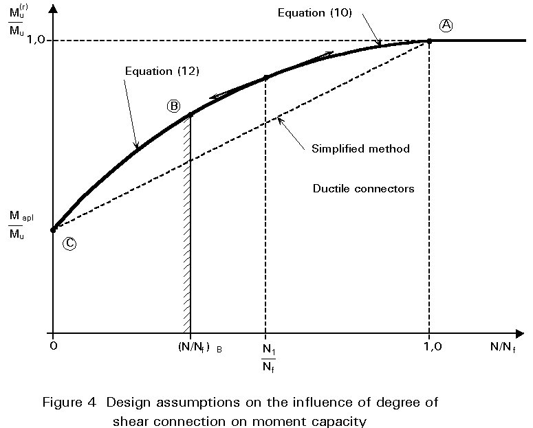
Finally, the global relationship between Mu(r) and N can be represented by a convex curve ABC, as shown qualitatively in Figure 4. This relationship can also be considered in a non-dimensional form (Mu(r)/Mu, N/Nf).
The convexity of curve ABC allows an alternative simplified approach which is always safe. This approach defines the moment resistance Mu(r) in terms of a linear interaction with the degree of shear connection N/Nf, such that:
Mu(r) = Muapl + (N/Nf)(Mu - Muapl) (13)
This "linear interaction method" is represented by the dashed line AC in Figure 4. Generally, a significant benefit may be obtained by using the stress block method, Equations (9) - (12), in the range of N/Nf = 0,5 to 0,7.
b) Ultimate loading of the beam
The above example assumes the simply supported beam is subject to either a uniformly distributed loading W or one concentrated load Q (see Figure 2). Since beam collapse is reached when a plastic hinge occurs in the critical cross-section subject to the maximum moment, it is logical to adopt an ultimate load curve W/Wu or Q/Qu, rather than Mu(r)/Mu, plotted against the connection degree N/Nf. Here, Wu or Qu corresponds to the ultimate load for full shear connection.
c) Requirement of minimum degree of shear connection
If the degree of shear connection is too low, the reduced ultimate moment curve will become irrelevant because connector failure will occur before flexural failure.
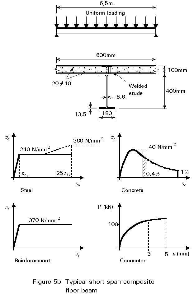
Figure 5a shows the results of numerical calculations for a uniformly loaded beam with a 6,5 m span. The cross-section dimensions and material properties are indicated in Figure 5b, and two different ultimate slip values, su, are considered for the connectors: 3mm and 5mm. Here, the curve ABC corresponds to the reduced ultimate moment curve according to the relationships in Equations (7) - (12). Assuming an elastic-perfectly plastic behaviour of steel, and su equal to 3 mm, the calculated values for W/Wu are plotted along the curve (1), representing 10 different degrees of connection, for the beam. It can be seen immediately that part BC of the moment curve is unsafe and therefore not usable. If strain-hardening is taken into consideration for the steel stress-strain curve (here a linear variation of sa from fy = 240 N/mm2 up to fu =360N/mm2 when ea lies between 10eay and 25eay), curve (1) is replaced by curve (2) which is safer, but the intersection of curve (2) with the reduced moment curve is almost the same as the intersection of curve (1). This result is logical since failure by stud rupture occurs in both cases and does not seem susceptible to the influence of strain-hardening. On the other hand, a favourable shift of the intersection point to the left can be observed if more ductile connectors are used, see curve (3), for which the ultimate slip su is assumed equal to 5mm.
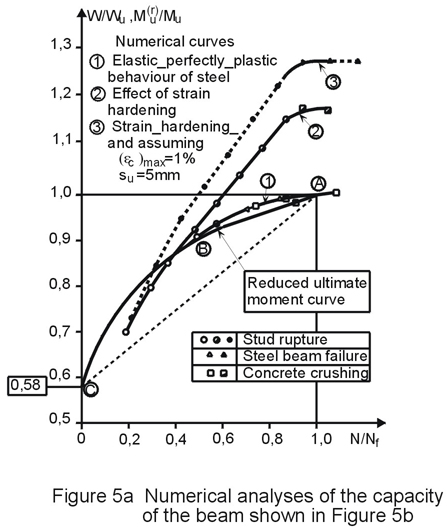
Theoretical investigation and experimental tests on beams have demonstrated that shear connector failure does not matter, provided that the method used to calculate the ultimate load gives the same degree of safety both for shear failure and flexural failure. The beam behaviour for shear failure may show as much ductility as for flexural failure, even for low degrees of connection, because ductile connectors used in practice have large deformation capacities. Consequently, the main problem is in locating the transition point, B in Figures 4 and 5, on the reduced ultimate moment curve, without having to use complicated methods. Another problem, which is not examined here, concerns the shape of diagram used to calculate the ultimate load associated with shear failure.
The first draft of Eurocode 4 [3] neglected shear failure and used only part AB of the reduced moment curve; it prescribed that the connection degree at point B, must not be less than (N/Nf)B=0,5, provided that the beam span does not exceed 20 metres. But a recent theoretical investigation [4] has demonstrated that this ratio is unsafe in some cases because the transition point B may shift rapidly to the right when the beam span L increases but is still less than 20 metres.
Eurocode 4 gives a more correct definition of the usable part AB of the reduced moment curve, taking into account that the connection degree (N/Nf)B must depend on the beam span L. Its specification, for ductile connectors, based on various research results in France and UK is as follows:
(N/Nf)B = 0,4 where L £ 5 m (14)
(N/Nf)B= 0,25 + 0,03 L £ 1 where L > 5 m (15)
(N/Nf)B = 0,4 + 0,03 L £ 1 (16)
The above formulae are appropriate for the case of headed studs in solid slabs. In the case of slabs cast on profiled steel sheeting it is reasonable to consider an increase in the ductility of the connectors and, therefore, the use of lower connection degrees; for example, the following formula is put forward:
0,4 £ (N/Nf)B = 0,04 L £ 1 (17)
for steel profiles with equal or unequal flanges.
Partial shear connection has several effects on beam behaviour at the serviceability limit state.
(a) For beams with partial shear connection, it has been found [5], that for a given load, maximum deflection d is related to the number N of connectors, by a curve similar to DEF in Figure 6; where df is the deflection for full connection and da is the deflection of the steel beam alone.
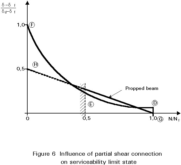
In practice, assuming values below 0,5 for the ratio N/Nf are not used, a reasonable approximation for d is given by the following relationship:
× for propped beams:
d = df + 0,5 (1 - N/Nf) (da - df) (18)
× for unpropped beams:
d = df + 0,3 (1 - N/Nf) (da - df) (19)
Another approach, which is valid for a larger interval of connection degree (0,2 £ N/Nf £ 1,0), and seems more accurate than Equations (18) and (19), calculates the elastic deflection d using an effective moment of inertia Ie for the partially composite beam. The effective moment of inertia is given approximately by:
Ie = Ia + (N/Nf)a(If - Ia) (20)
where If and Ia are the moments of inertia of the full composite and steel sections respectively, and the exponent a is dependent on the beam span L.
Convenient practical values of a have been suggested [4], such as 1,5, 1,0 and 0,8 when L is equal to 5, 10 and 15 metres respectively.
b) The effect of partial shear connection on the increase of stresses in concrete and steel extreme fibres is generally neglected when N/Nf lies between 0,5 and 1. If N/Nf lies within a larger interval (0,2 £ N/Nf £ 1,0), it is possible to use an effective section modulus We (which refers to the tension flange of the steel section) given by:
We = Wa + (N/Nf)b(Wf - Wa) (21)
where Wf and Wa are the section moduli of the full composite and steel sections respectively, and the exponent b is approximately equal to a/2 [4].
c) In addition, the connector behaviour must remain reversible at the serviceability loads. This reversible behaviour is ensured by requiring that the shear force on each connector does not exceed 0,7 PRd. To check this requirement is met, it is possible to use an elastic analysis such as that presented in Section 3; if N/Nf is not too low (for example N/Nf ³ 0,5), this analysis can be assumed valid for ductile connectors working in the reversible part of their load-slip curve.
[1] Aribert, J.M. et Abdel Aziz K., "Calculation of Composite Beams up to Ultimate State with the Effect of Uplift at Steel-Concrete Interface", Revue Construction Métallique no 4 - 1985 - p 3-36.
[2] Aribert, J.M. et Abdel Aziz K., "General Model for the Ultimate State Design of Statically Indeterminate Composite Beams", Revue Construction Métallique no 4 - 1986 - p 3-41.
[3] Eurocode 4: "Design of Composite Steel and Concrete Structures": ENV1994-1-1: Part 1.1: General rules and rules for buildings, CEN (in press).
[4] Aribert, J.M., "Span Limitations in Design of Composite Steel and Concrete Beams with a Partial Shear Connection", IABSE Symposium Brussels, Belgium - Theme 1 - September 5-7 1990.
[5] Johnson, R.P., "Composite Structures of Steel and Concrete - Volume 1", Crosby Lockwood, 1975.