ESDEP WG 10
COMPOSITE CONSTRUCTION
To explain the design of shear connection in continuous composite beams, with special emphasis on hogging moment regions.
Lectures 10.6: Shear Connection
Lectures 10.4: Continuous Beams
Lectures 10.5: Design for Serviceability
The aim of the lecture is to explain simply the basis of designing full and partial shear connection in continuous composite beams, mainly dealing with the connector distribution in hogging moment regions. The greatest care must be taken regarding the validity of plastic cross-section behaviour. For critical cross-sections in Class 1, a general method is developed, illustrated by examples. For critical cross-sections in Class 2, an outline is given using a simplified method.
This lecture describes the design of shear connection in continuous composite beams. The problem is discussed mainly with regard to a practical method for determining the connector distribution along the shear span in the hogging moment region. The use of partial shear connection in a continuous beam is considered; this is a complicated problem which must be related to the validity of plastic theory and take account of the increased risk of local flange buckling at internal supports.
The design of the shear connection in a continuous beam is more complicated than for a simply supported beam because of hogging bending effects over the internal supports. The cross-sections in these regions may become critical and have to be checked. Checking them is complicated by the decrease in bending stiffness (due to slab cracking) and the tendency for the neutral axis to move up the steel web, if slab reinforcement is used, thereby changing the classification of the section elements (according to the definitions given in Lecture 10.3). In such situations, the scope for the application of rigid-plastic analysis of beams is more restricted. There is then the need to distinguish between several procedures for connection design.
Before describing the procedures the following points should be noted:
The very simple example of a two-span continuous beam under concentrated loading is taken below to illustrate the procedures.
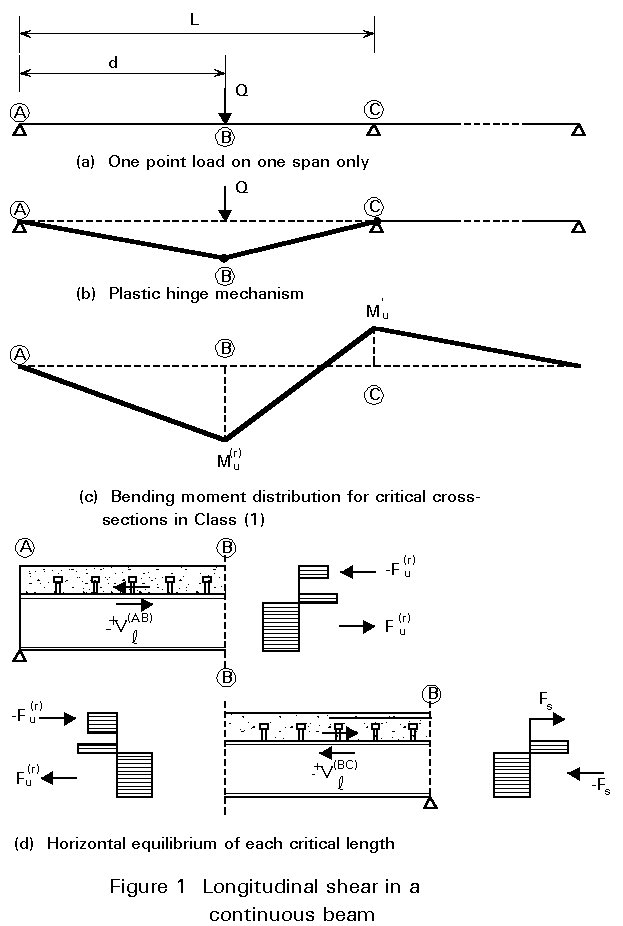
Figure 1a shows a span AC of a two-span composite beam, loaded by a single concentrated load Q, at point B. A design method is now developed for both partial and full shear connection of the beam. At failure, a complete plastic mechanism is assumed to occur (Class 1 sections), see Figure 1b, with the bending moment reaching the ultimate cross-section resistance at each plastic hinge location. If these moments are assumed to be Mu(r) and M¢u, in sagging and hogging respectively (see Figure 1c), then the ultimate load is given by the relationship:
Q = {Mu(r)L + M¢ud}/[d(L - d)] (1)
Clearly, the values of Mu(r) and M¢u depend on the arrangement of the shear connection. As explained in Lecture 10.4.1, the calculation of the hogging moment of resistance M¢u is based on the following assumptions:
Fs = asfsk /gs (2)
The critical length BC, where the bending moment changes sign, is considered first. The number N(BC) of ductile shear connectors uniformly distributed along this critical length can be chosen. The horizontal equilibrium condition (see Figure 1d), for the concrete slab, gives the equation:
Vl(BC) = N(BC) PRd = Fu(r) + Fs (3)
where Vl(BC) is the total longitudinal shear force in the critical length considered, and Fu(r) is the compressive force in the concrete slab in the internal critical cross-section B. Hence, the value of Fu(r) can be determined:
Fu(r) = N(BC) PRd - Fs (4)
and consequently the reduced ultimate sagging moment Mu(r) by using Equations (10) and (12) established for simply supported beams (see Lecture 10.6.2).
Considering the external critical length AB, which is only in sagging bending, the required number N(AB) of shear connectors follows directly from the Equation:
Vl(BC) = N(AB) PRd = Fu(r), (5)
hence:
N(AB) = Fu(r)/PRd = N(BC) - Fs/PRd (6)
Finally, the total number N of shear connectors uniformly distributed along the whole span AC is equal to:
N = N(AB) + N(BC) = 2 N(BC) - Fs/ PRd (7)
In summary, using the parameter N(BC), the ultimate load Q of the beam, Equation (1), can be calculated as a function of the total number N of shear connectors, Equation (7), in the span concerned by assuming a plastic failure mechanism occurs. Obviously, the case of full shear connection corresponds to the particular value Nf(BC) such that Equation (4) leads to the maximum value of Fu(r), i.e. Vlf given by Equation (4) Lecture 10.6.2. Therefore:
Nf(BC) = (Vlf + Fs)/PRd (8)
The corresponding values of the total number of shear connectors and the ultimate load of the beam are defined by symbols Nf and Qu.
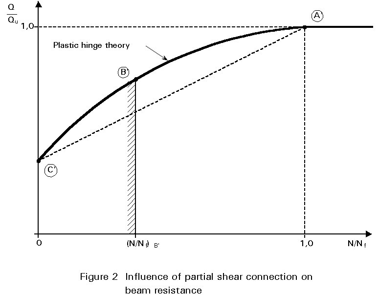
To illustrate the above results, Figure 2 gives a graphical representation of the relation between Q and N (in non-dimensional form), namely the qualitative curve A¢B¢C¢ . For the same reasons as explained in the case of simply supported beams, the whole curve A¢B¢C¢ is not usable; as before, the minimum number of shear connectors must be limited to a function of the span L of the beam. Therefore:
![]() (9)
(9)
where the limitation (N/Nf)B¢ may again be evaluated by means of Equations (15) and (16) given in Lecture 10.6.2. Such an evaluation is conservative because partial shear connection deals here only with the region in sagging bending, and this region is shorter than L.
The following observations are made regarding the above approach:
(i) The formulae derived are based on an assumed zero value for the compressive force possibly developed in the concrete at the intermediate support. This is a conservative assumption and an increase in design resistance may result from a more detailed analysis [3].
(ii) The curve A¢B¢C¢ shown in Figure 2, is always convex, like curve ABC in Fig. 4 of Lecture 10.6.2. This property results directly from Equation (1) and the negative value of the second derivative of function Mu(r)(N(AB)), and consequently function Mu(r)(N). A simplified method can be proposed for the determination of the ultimate load Q of the continuous beam with partial shear connection. This method is again based on linear interpolation between the ultimate load Qapl of the steel beam alone and the ultimate load Qu of the composite beam with full shear connection:
Q = Qapl + ![]() (Qu - Qapl) (10)
(Qu - Qapl) (10)
(iii) As has already been explained, Q can be calculated when the number of shear connectors and their distribution, is known. Vice versa, when Q is fixed, curve A¢B¢C¢ or line A¢C¢ allows the determination of the total number N of shear connectors and their distribution can then be determined from Equation (7), then (6).
(iv) The discussion thus far has concentrated on the particular load/span arrangement shown in Figure 1. However, it is clear that the same principles can easily be applied to other more general cases of continuous beams. For these cases, Equation (1) (used to calculate the ultimate load) will be different and the definition of the critical lengths related to the plastic mechanism at failure may be more subtle. Section 2.2.2 covers situations where several point loads and/or distributed loads are applied on any span of a continuous beam.
Figure 3 shows the case of two equal point loads each located at a quarter span from the supports. The cross-section at point B is the critical one and the corresponding ultimate load is given by the relationship:
Q = (4Mu(r) + M¢u)/L (11)
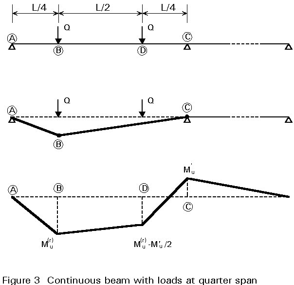
However, if the ultimate value of Q is relatively large, compared to the section resistance, an intermediate cross-section must be introduced at point D, resulting in the connectors not being spaced uniformly along the internal critical length BC.
Figure 4 shows a symmetrical two-span beam with a uniformly distributed load "q". The shear connection design requires that the location of the critical cross-section B should be calculated from consideration of the plastic hinge mechanism. Therefore:
d = L(Mu(r)/M¢u){Ö[1+ (M¢u/Mu(r))]-1} (12)
and the corresponding value of the ultimate load is:
q = 2[Mu(r)L + M¢ud]/[d(L-d)L] (13)
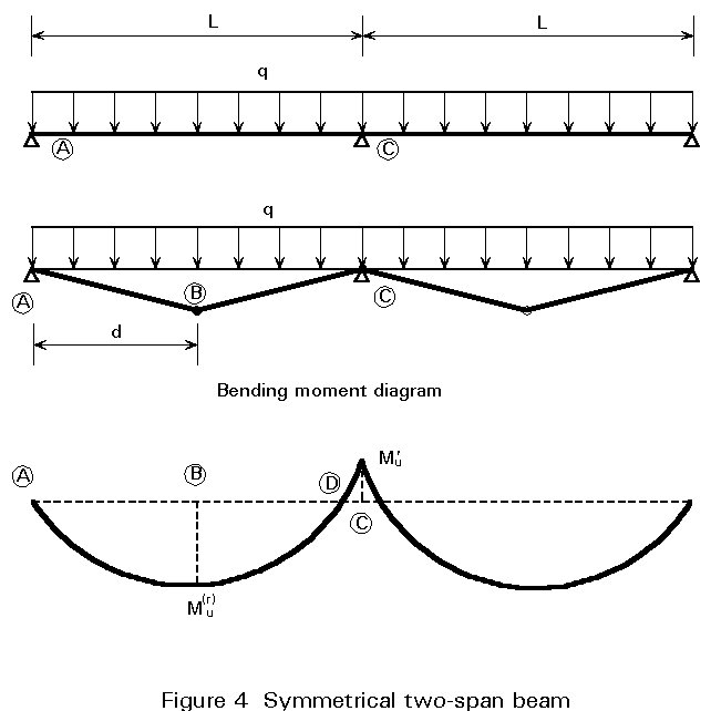
In contrast to Figures 1 and 3, here the location of the critical cross-section B is slightly affected by the choice of the number N(BC) of shear connectors; this makes the determination of the curve (q/qu, N/Nf), similar to curve A¢B¢C¢ in Figure 2, more difficult. The interpolation method, however, is still valid, symbol Q being replaced by symbol q in Equation (10).
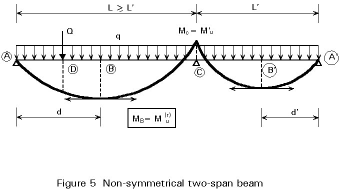
Finally, Figure 5 shows a more complicated case: an unsymmetrical two-span beam on which a uniformly distributed load q is applied together with a heavy point load Q on the longer span only. In this case, the position of critical cross-sections B and B¢, in sagging moment, should be found (see d and d¢ in the Figure), and the critical length AB should be divided into two sub-lengths by introducing the intermediate cross-section D for checking the adequacy of the shear connection. The internal critical length BC can be designed in accordance with the general method or the simplified one. For the internal critical length CB¢, which is not part of the plastic hinge mechanism, its shear connection can be designed by interpreting the external bending moment MB¢ at failure as equal to a reduced plastic resistance moment in the cross-section B¢. It should be noted that the same interpretation is used for intermediate cross-sections.
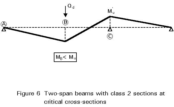
Class 2 cross-sections are discussed here together with cross-sections with Class 3 webs which can be replaced by an effective web in Class 2 using area reduction. Referring to the simple example of Figure 1, the ultimate design load for the beam cannot be calculated using plastic hinge analysis. Only an elastic global analysis with limited redistribution of moments can be used for the beam, which leads to an ultimate load Qd less than the corresponding value Qu for a Class 1 beam with full shear connection. Since MB < Mu in the sagging moment region, as shown in Figure 6, it is clear that partial shear connection will occur even when the beam is used to its full flexural resistance. Attention must be paid here to the fact that the convex curve A¢B¢C¢, in Figure 2, cannot be used to calculate the total number N of shear connectors in span AC because, the plastic hinge mechanism cannot occur at the Class 2 cross-section B. In practice, however, a line similar to A¢C¢ can be used for this problem, as it gives safe results. Therefore, in the absence of a more rigorous calculation, the degree of connection N/Nf may be calculated from the linear relationship:
N/Nf = (Qd - Qapl)/(Qu - Qapl) (14)
It should be noted that Qu and Qapl are calculated now using elastic global analysis.
[1] Eurocode 4: "Design of Composite Steel and Concrete Structures": ENV1994-1-1: Part 1.1: General rules and rules for buildings, CEN (in press).
[2] Johnson, R.P., "Composite Structures of Steel and Concrete - Vol. 1." Crosby Lockwood, 1975.
[3] Stark, J.W.B., "Composite Steel and Concrete Beams with Partial Shear Connection", Heron, Vol. 34, No. 4, 1989.