ESDEP WG 10
COMPOSITE CONSTRUCTION
To describe the effects of cracking of concrete and yielding of steel on the distribution of bending moments; to explain methods of elastic structural analysis which allow for these effects and for local buckling of the structural steel section, and to discuss lateral-torsional buckling in continuous composite beams.
Lecture 7.2: Cross-section Classification
Lecture 7.3: Local Buckling
Lectures 7.9: Unrestrained Beams
Lecture 10.2: Behaviour of Beams
Lecture 10.3: Single Span Beams
Lecture 10.4.1: Continuous Beams I
Lectures 10.5: Design for Serviceability
Lectures 10.6: Shear Connection
Lecture 10.10: Composite Bridges
Worked Example 10.3: Design of a Continuous Composite Beam
Elastic analysis for internal moments and forces in continuous composite beams is of more general application than plastic analysis. Redistribution is permitted, to allow for cracking of concrete and yielding of steel in the negative moment regions. The extent of the redistribution depends on the classification of cross-sections at internal supports and the assumptions made concerning the flexural rigidity in hogging bending.
For a cross-section in Class 3 or Class 4, stresses should be calculated by elastic theory, using an effective width for the concrete flange. Account may be taken of creep of concrete in compression by means of an appropriate modular ratio.
The typical pattern of bending moments in a continuous beam results in the lower flange being in compression over internal supports. As the upper flange of the steel section is restrained by the concrete slab, lateral buckling of the compression flange is accompanied by distortion of the cross-section. Account can be taken of the distortional stiffness to reduce the effective slenderness for lateral-torsional buckling.
The design methods established in the lecture are illustrated by Worked Example 10.3.
Bending moments in continuous composite beams at the ultimate limit state (ULS) may be determined by elastic analysis or, subject to certain conditions, rigid-plastic analysis; the latter method is discussed in the previous Lecture 10.4.1. Elastic analysis has the advantage of more general application, and may also be more convenient to use as this approach is also required to check the serviceability limit state (see Lectures 10.5.1 and 10.5.2).
In composite building structures no consideration of temperature effects is normally necessary in verifications for ULS. Similarly, the effects of shrinkage may be neglected, except in analysis involving Class 4 sections. These effects, therefore, are not considered in this lecture.
The scope of Eurocode 4 [1] does not include members with semi-rigid connections. Thus this lecture concerns beams in which the steel section is either continuous over simple supports or is jointed by rigid connections.
In general, elastic analysis requires that the relative stiffnesses of adjacent spans be known. As the stiffnesses depend on the second moment of area of cross-sections, it is necessary to know the effective width of the concrete flange and the modulus of elasticity of concrete relative to that of steel (the modular ratio).
An effective width approach is used to make allowance for in-plane shear flexibility (shear lag). Values of effective width may be related to distances along the beam between points of zero bending moment. Different values can be calculated therefore for sagging moment regions and hogging moment regions, as described in Fig. 10 of the previous lecture (taken from Fig. 4.3 of Eurocode 4 [1]). For global analysis, however, it has been found that shear lag has little effect on the results. Hence a constant effective width may be assumed for the whole of each span, which greatly simplifies the analysis. As the greater part of each span of a beam will usually be subject to sagging bending moment, it is appropriate that the constant effective width be taken as the value at mid-span. For a cantilever, however, the width should be that applicable at the support.
In determining the elastic section properties, the concrete is usually assumed to be uncracked under positive sagging moment. If the slab is formed with profiled steel sheeting whose ribs are transverse to the steel section, as discussed in Lecture 10.1, the area of concrete within the profile depth is ignored.
The elastic section properties of a composite beam may be expressed as those of an equivalent steel section by dividing the effective width of the concrete flange by a modular ratio. Account is taken of the effects of creep of concrete in compression by choice of an appropriate value for the ratio, as described in Lectures 10.5.1 and 10.5.2.
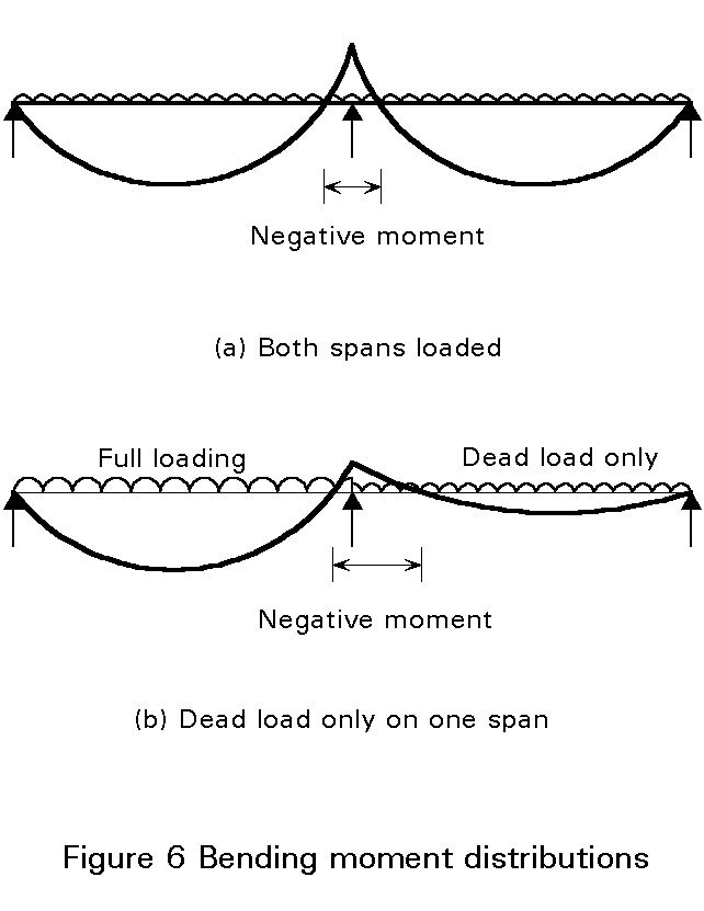
For continuous beams in buildings, without cantilevers, subject to mainly uniformly distributed loading, only the following arrangements of variable load need be considered:
In both cases, the same value of the partial safety factor, gG, for permanent load may be taken for each span, whether or not such load on a particular span is a favourable or unfavourable action.
Loss of stiffness due to cracking of concrete in negative moment regions has more effect on distribution of bending moment in continuous composite beams than in continuous reinforced concrete members. This is because in the latter loss of stiffness also occurs due to cracking in the mid-span regions. It has been found that in continuous composite beams the bending moment at an internal support at the serviceability limit state (SLS) may be 15 to 30% lower than that given by an elastic analysis in which no account is taken of cracking. At the ultimate limit (ULS) the distribution of moments will also be influenced by yielding of steel.
The redistribution of moments cannot be predicted accurately because the longitudinal tensile stress in the concrete slab, in negative moment regions, is influenced by the sequence of casting and the effects of temperature and shrinkage, as well as by the proportions of the composite member and the dead and imposed loading. A wide variation in flexural rigidity can occur along a composite beam of uniform cross-section, leading to uncertainty in the distribution of bending moments and hence the amount of cracking to be expected.
Two methods of elastic global analysis are permitted by Eurocode 4 [1] for the ultimate limit state:
Both may be used in conjunction with redistribution of support moments, the degree of redistribution being dependent on the susceptibility of the steel section to local buckling.
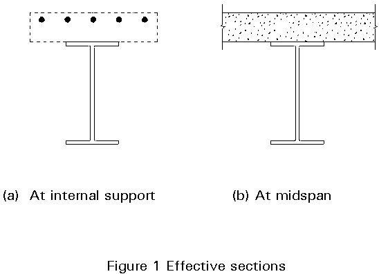
It is assumed that for a length of 15% of the span on each side of internal supports, the section properties are those of the cracked section for negative moments. The assumption of a fixed proportion of the span as "cracked" is a considerable simplification, since it makes feasible the use of formulae or standard computer programs for the global analysis, without the need for iteration. The second moment of area of the cracked section is calculated using a section comprising the steel member together with the effectively anchored reinforcement located within the effective width of the concrete flange at the support (see Figure 1a). Outside the "15% length", the section properties are those of the uncracked section. They are calculated using the mid-span effective width for the concrete flange but ignoring any longitudinal reinforcement (Figure 1b).
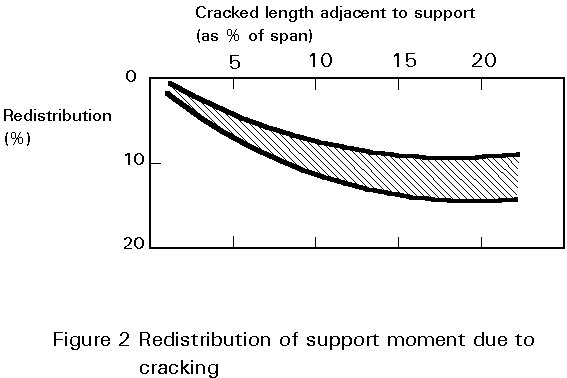
The effect of assuming a length other than 15% to be cracked has been studied (see Figure 2). It was found that bending moments calculated assuming a cracked length of 15% would be correct to within 5% if any proportion of the span between 8% and 25% was in fact cracked; the simplifying assumption is therefore justified.
The properties of the uncracked section are used throughout. Thus, the analysis is not dependent on the amount of reinforcement over the supports. Indeed for a continuous beam of uniform section, the analysis can be carried out without any prior calculation of the cross-section. For equal spans, standard bending moment coefficients from reference books can be used.
Design codes commonly permit negative (hogging) moments at supports to be reduced, except at cantilevers, by redistribution to mid-span. The extent of the redistribution is dependent, in part, on the method of analysis, as shown in Table 1, which is taken from Eurocode 4 Table 4.3 [1].
Table 1 also shows that the degree of redistribution depends on the classification of the cross-section at the supports (the limits which define the various classes of composite section will be discussed further in a later part of this lecture).
Consider first a Class 4 section, i.e. one in which local buckling may prevent the design resistance from being attained. If redistribution is less than the designer assumes, the steel web or the compression flange at the support may buckle prematurely. For safety therefore, the maximum amount of redistribution to mid-span must be no greater than the minimum redistribution likely to occur in practice. Redistribution is therefore not permitted if a "cracked" analysis has been used.
Studies on composite beams with critical sections in Class 3 or Class 4 have shown that provided at least 10% of the span is cracked, as is likely in practice, the reduction in support moment due to cracking will exceed 8% (Figure 2). It is reasonable to assume therefore that in round terms the difference between an 'uncracked' and a 'cracked' analysis with such beams is equivalent to 10% redistribution of the 'uncracked' support moments, as shown in Table 1 for Class 3 and Class 4 sections.
There is no need to be so cautious for Class 3 ("semi-compact") sections as these can reach the design resistance, with local buckling only preventing the development of the full plastic moment. Numerical analysis, using experimental data on the falling branch of moment-rotation relationships for locally-buckling Class 3 cantilevers, confirms that up to 20% redistribution can be allowed, as given in Table 1.
In a Class 2 section the full plastic moment resistance can be developed. It has been proposed that a redistribution of 30% be permitted from an "uncracked" analysis to allow for local yielding at the supports and cracking of concrete. Comparisons with test results made during the assessment of Eurocode4 confirm the latter figure as appropriate for sections which can attain the plastic resistance moment at the supports.
A beam with Class 2 (or Class 1) sections at supports will typically have a relatively low neutral axis, in order to meet the restrictions on the depth of the web in compression required in such sections. Hence only light tensile reinforcement can be provided and the ratio of "uncracked" to "cracked" flexural stiffness (I1/I2) can exceed 3.0. For such beams, the bending moment at the internal support from "cracked" analysis may then be less than 70% of the value from "uncracked" analysis and is almost always less than 85% of the "uncracked" value. This contrasts with the studies referred to above and summarised in Figure 2, for which the ratio I1/I2 was nearer 2 than 3. It follows that for Class 2 and Class 1 sections a 15% difference between "uncracked" and "cracked" analysis is more appropriate than the 10% difference adopted for beams with sections in Class 3 or Class 4. A 15% difference is given in Table 1 for Class 2 and Class 1 sections.
Finally, a Class 1 section is one which can, not only attain the plastic resistance moment, but also sustain this level of moment whilst rotation occurs. In steel structures, the limits on flange and web slenderness which define a 'plastic' section are sufficiently restrictive to permit plastic global analysis without further checks on rotation capacity. This is not true for composite beams, partly because the degree of redistribution needed to attain a plastic hinge mechanism will be higher due to the greater relative moment resistance at mid-span. The conditions required for plastic global analysis have been discussed in the previous lecture. The redistribution of elastic support moments permitted in Table 1 for Class 1 sections is based on the recognition that some rotation capacity exists for such sections.
The limitations on flange slenderness and web slenderness for Class 1 and Class 2 sections have been given in the previous lecture. For a section in Class 1 or Class 2, the bending resistance can be calculated by rectangular stress block theory, as described in Lectures 10.3 and 10.4.1. The determination of the plastic resistance moment is not considered further in this lecture.
The limiting slendernesses for Class 3 cross-sections are those beyond which local buckling occurs in the structural steel section prior to the yield stress being reached. It is logical, therefore, that the limits for composite beams, without web encasement, are the same as those for steel beams. Eurocode 4 [1] specifies these, as shown in Tables 1a and 1b of Lecture 10.4.1; a Class 4 section is one which does not comply with these requirements.
Web encasement may be assumed to contribute to resistance to local buckling provided that it is reinforced and mechanically connected to the steel section. A Class 3 web which is encased, may be treated effectively as if it was in Class 2.
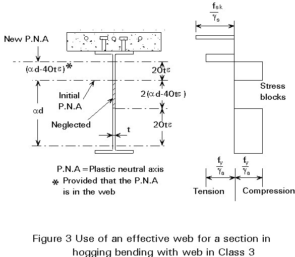
Provided the flanges are Class 1 or Class 2, the moment resistance of a section with an uncased web in Class 3 may still be determined by plastic analysis, provided that part of the web is discounted. The resulting effective section in hogging bending is shown in Figure 3. Without this approach, change of classification of the web from Class 2 to Class 3, due to small changes in longitudinal reinforcement, would prevent plastic analysis from being used. As a consequence, the calculated resistance moment would be unduly sensitive to changes in reinforcement.
Following global analysis at ULS, it is necessary to ensure that the proposed sections possess adequate resistance to the internal moments and forces.
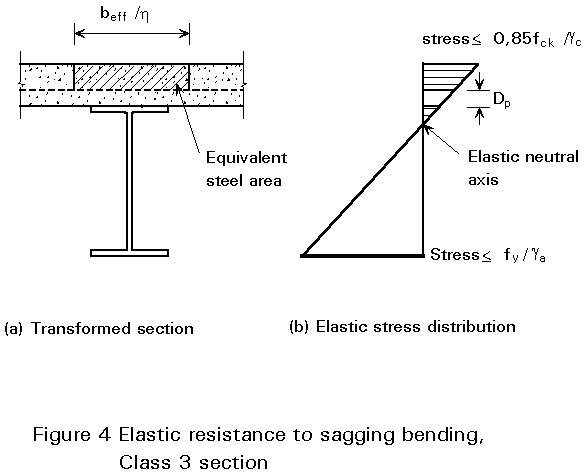
For a section in Class 3 or Class 4, stresses should be calculated by elastic theory. To determine the section properties, allowance should be made for shear lag using the appropriate effective width of the concrete flange for sagging or hogging bending (see Figure 10 of Lecture 10.4.1). In the analysis it is assumed that strain varies linearly over the full depth of the composite cross-section. This implies that there is negligible slip at the steel-concrete interface. Use is made of the theory of transformed sections, assuming that both concrete in compression and steel are linearly elastic materials. This assumption enables the composite section in sagging bending to be replaced in the analysis by an equivalent all-steel cross-section. The breadth of the equivalent steel slab depends upon the modular ratio ae, defined by:
ae = Ea/E1c
where Ea is the elastic modulus of steel.
E1c is an appropriate elastic modulus for concrete.
The transformation is illustrated in Figure 4a for the case where the slab is formed with profiled sheeting. The ribs of depth Dp run transverse to the beam and all concrete above the ribs is in compression. The area of concrete within the depth of the profiled steel sheet is ignored.
As elastic theory is being used, calculations are therefore similar to those to be made for all classes of section when checking serviceability, and reference should be made to Lectures 10.5.1 and 10.5.2 for detailed explanation of the analysis of the transformed section. Account should be taken of creep of concrete in compression due to permanent loads by use of an appropriate value for the modular ratio.
In hogging bending, the whole of the concrete slab may be assumed to be cracked. The effective section therefore comprises the structural steel section and effectively anchored reinforcement within the effective width for hogging bending (Figure 5a).
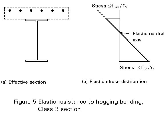
The ultimate bending resistance of the member is attained when a stress reaches the limiting strength of one of the components in the cross-section. In Eurocode 4 [1] the limiting strengths for ULS are as follows:
These limits are illustrated in Figure 4b for a section in sagging bending and in Figure 5b for a section in hogging bending. In the particular cases shown, the neutral axes are in the structural steel section.
For sections in Class 4, account should be taken of local buckling, for example by using effective widths for the compression elements as described in Eurocode 3 [2] and discussed in Lecture 7.3.
Where unpropped construction is used, stresses due to loads on the structural steelwork alone need to be added to stresses due to loads on the composite member.
When high vertical shear co-exists with high bending moment, account needs to be taken of the resulting interaction. The manner in which vertical shear affects the plastic resistance moment has been described in Lecture 10.3. For sections in Class 3 and Class 4, Section 4.4.3 of Eurocode 4 generally reduces the elastic resistance moment to account for vertical shear.
In composite beams, the upper flange of the steel section is restrained against lateral buckling by the concrete slab. However, the typical pattern of bending moments in a continuous beam (see Figure 6a) results in the lower flange being in compression in the region of internal supports. The length of the lower flange in compression can be considerable when only dead load acts on the span under consideration (Figure 6b).
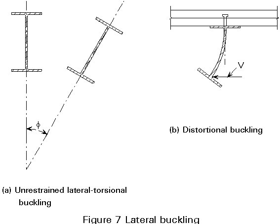
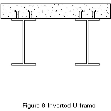
Methods for the design of unrestrained steel beams against lateral-torsional buckling, as discussed in Lectures 7.9.1 and 7.9.2, are not applicable to negative moment regions of continuous composite beams because in the former case it is assumed that each cross-section of the member rotates as a whole, without distortion (see Figure 7a). In the negative moment region of a composite member, the restraint afforded to the upper flange results in distortion of the cross-section if the lower (compression) flange is to buckle laterally (Figure 7b). This restraint is provided by the torsional stiffness of the slab, acting together with adjacent steel sections as an inverted U-frame (Figure 8). The effectiveness of the restraint is also dependent on the stiffness of the shear connection.
For composite beams whose steel member is a conventional hot-rolled I-section, inverted U-frame action may provide full restraint to the lower (compression) flange. The conditions under which this can be assumed to be achieved are given in Section 4.6.2 of Eurocode 4 [1]; they include some limitation on the depth of the steel member, the restriction becoming more severe as the design strength of the steel increases.
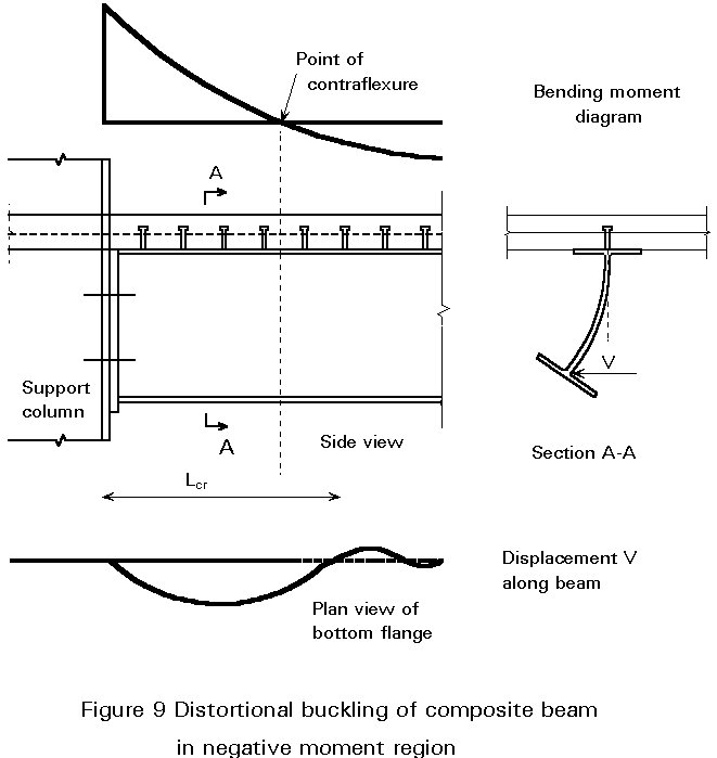
The effect of the restraint to the compression flange resulting from the distortional stiffness of the cross-section, and other components in the U-frame action, can also be accounted for by reducing the effective slenderness of the beam when calculating the buckling resistance moment. Despite the possibility of local plastification at the ends of the beam, the plastification is not considered to affect the elastic mode of instability of the beam (Figure 9) because of the reducing negative moment over the buckled length. A method for the calculation of the slenderness is given in Eurocode 4, Annex B [1].
The above method relates to the lateral stability of the member between restraints. Two possible forms of discrete lateral restraint of the lower compression flange are shown in Figure 10. It is necessary to ensure that such restraint is sufficiently strong and stiff to be effective and that the pull-out strength of the shear connectors is not exceeded. It is usual to check the resistance of the restraint components to a lateral force calculated as a small percentage of that in the compression flange. This is discussed further in Lecture 10.10 on composite bridges.

[1] Eurocode 4: "Design of Composite Steel and Concrete Structures": ENV1994-1-1: Part 1.1: General rules and rules for buildings, CEN (in press).
[2] Eurocode 3: "Design of Steel Structures": ENV1993-1-1: Part 1.1: General rules and rules for buildings, CEN, 1992.
The references given in Lecture 10.1 are also relevant.
Table 1 Limits to redistribution of moments, per cent of the initial value of the bending moment to be reduced
|
Class of cross section in hogging moment region |
1 |
2 |
3 |
4 |
|
For "uncracked" elastic analysis |
40 |
30 |
20 |
10 |
|
For "cracked" elastic analysis |
25 |
15 |
10 |
0 |