ESDEP WG 15B
STRUCTURAL SYSTEMS: BRIDGES
To introduce the main concepts and definitions concerning suspension bridges.
None
Lecture 4A.4: Corrosion Protection of Bridges
Lecture 15B.1: Conceptual Choice
Lecture 15B.3: Bridge Decks
Lecture 15B.4: Plate Girder and Beam Bridges
Lecture 15B.5: Truss Bridges
Lecture 15B.6: Box Girder Bridges
Lecture 15B.8: Cable Stayed Bridges
The lecture begins with a historical introduction to suspension bridges with emphasis on the specific 'jumps' in the development of their spans. The various types of suspension bridge are discussed and their main parts are separately presented, i.e. main cables, hangers, pylons and stiffening girders.
The influence of temperature and aerodynamic excitation are introduced. Finally, some notes on structural analysis and erection are given.
Generally, cable supported bridges can be divided mainly in two groups, cable stayed bridges (see Lecture 15B.7) and suspension bridges. Their use leads to a competitive solution for spans between 200m and 1500m (and beyond). They cover therefore the major part of the present span range of bridges. These two groups, although similar in philosophy, have many differences in practice. One of the main reasons for their superiority in relation to other forms of bridge is the most efficient way in which they use materials, i.e. direct stress under which all the fibres have the same stress resulting in full utilization of the material.
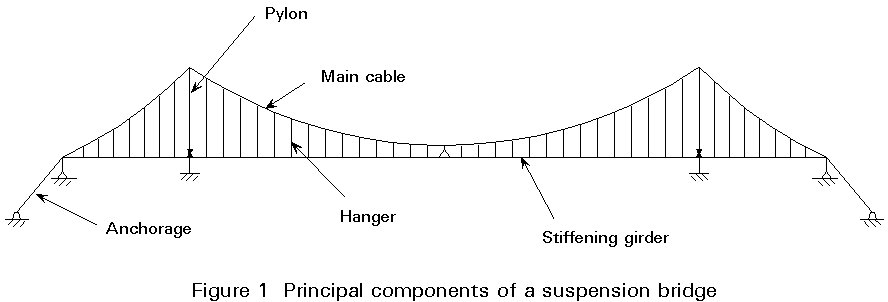
In this lecture the conventional suspension bridge is discussed. Relevant nomenclature is given in Figure 1.
Since the beginning of the 19th century, suspension bridges have gradually grown in size, and since 1930 the suspension bridge has completely dominated the upper span range.
The following table indicates the development of spans:
|
Bridge |
Place |
Year |
Mid span (m) |
|
Menia Straits Bridge Clifton Suspension Bridge Cincinnatti and Covington Suspension Bridge Brooklyn Bridge Philadelphia-Camden Bridge George Washington Bridge Golden Gate Bridge Tacoma Narrows Bridge Mackinac Firth of Forth Severn Bridge Humber Bridge Great Belt East Bridge Akaski Kaikyo Bridge (Figure 2) |
Wales England USA USA USA USA USA USA USA Scotland England England Denmark Japan |
1826 1860 1865 1883 1926 1931 1937 1940 1958 1964 1966 1981 1997* 1998* |
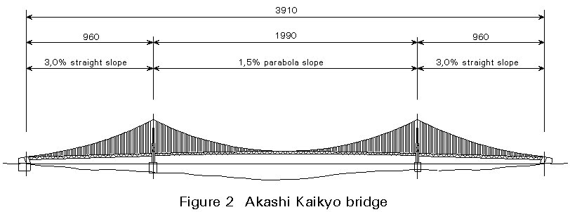
168 214 322 480 535 1066 1280 853 1158 1002 988 1410 1624 1990 |
The Akaski Kaikyo Bridge is shown in Figure 2.
From this table two specific 'jumps' in the development of spans can be distinguished:
As the design of suspension bridges continued to develop, the girder became lighter and lighter, the main girder torsionally weaker and weaker and designers more and more audacious.
A rude awakening came in November 1940 when the Tacoma Narrows Bridge collapsed due to wind effects.
Since then, the progress that has been made has been due to:
a. New concepts, e.g. orthotropic decks.
b. New methods of analysis, e.g. electronic computers.
c. New materials, e.g. high-strength steel and concrete.
d. New fabrication and erection methods (bolting, welding, mass production, modern equipment, etc).
e. Better quality control.
f. Better understanding of wind and seismic forces, e.g. derived from wind tunnel tests, etc.
The majority of all suspension bridges carry road traffic only, but a limited number carry rail traffic as well.
In more special applications, the suspension system is also used for pedestrian bridges and for pipeline bridges.
Suspension bridges may be subdivided according to several criteria:
a. Suspension of the girder:
× Both the main span and the side spans are suspended: the S-type, Figure 3(a)
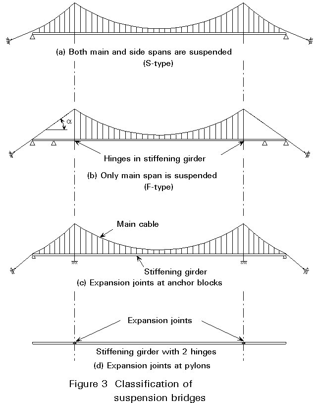
× Only the main span is suspended and, the end spans are substituted by independent approach spans: the F-type, Figure 3(b).
For the F-type, the back stays have a slope corresponding to a = 30 - 45°. This slope determines the position of the anchorage and with straight back stays the tower top is well supported against horizontal displacements. As compared with the S-type, with 2 hinges (code: S2), the F2-type is stiffer.
b. Anchorage of the main cable:
× In present practice, all major suspension bridges are earth anchored with separate anchorages allowing the main cable forces to be transmitted to the soil.
c. Position of expansion joints (Figure 3(c) and (d))
The stiffening girder can have its expansion joints positioned at the pylons or at the anchor blocks.
Corresponding to these two conditions the stiffening girder will either consist of three individual girders or one continuous girder.
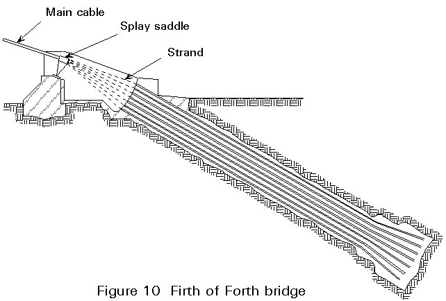
The main cables run from anchorage to anchorage.
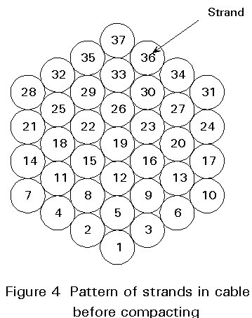
A cable is composed of a number of strands. These strands can be made in situ by cable spinning or they are prefabricated.
The number of strands builds up in a simple arithmetric progression. The cable thus consists of a central strand surrounded by 6 strands, 6 + 12 strands, 6 + 12 + 18 strands, etc.
The cable in Figure 4 contains 37 strands and this is a common number in bridges with spun cables. (The numbers indicate the sequence of spanning the individual strands.) Thus, in the Humber Bridge the main cables are composed of 37 strands: each having 404 wires.
In bridges with main cables made of parallel wire strands, the number of strands is generally higher as each strand has to contain fewer wires for reasons of handling.
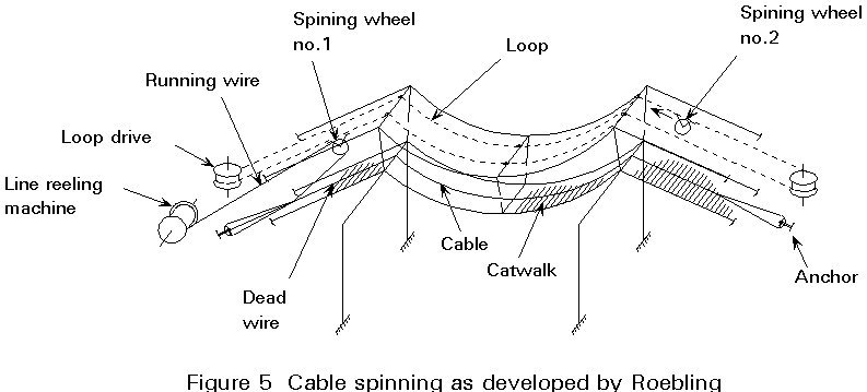
Before starting the main cable erection a catwalk is made, running from anchorage to anchorage via the pylon tops. A tramway is mounted on this catwalk if the cables are to be spun. The tramway is not necessarily required for the transport of prefabricated strands. To protect the catwalk to some extend against the wind, a pretensioning system of counter parabolas is used.
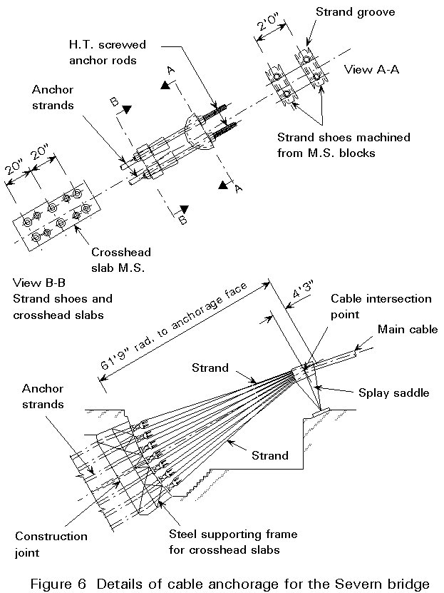
The essentials of the cable spinning process are shown in Figure 5. The catwalk and tramway are indicated. Two spinning wheels, connected to a loop, carry separate wires from one side to the other. At one of the anchor blocks the dead wire is fixed. On the other side the wire is taken off the spinning wheel and looped around a strand shoe (Figure 6). Next the live wire is fixed. When a strand, consisting of 300 to 400 wires, is finished, this strand is located carefully in its correct place. This operation is carried out at night when the temperature is nearest to uniform.
The optimum wire diameter is 5,0-5,5mm. A larger diameter makes the wire too stiff, while a smaller diameter requires more wires and more labour. The wire material has an ultimate strength up to 1600 - 1800N/mm2.
With span cables, each working shift can mount about 160 wires a day, and in most cases two shifts per day per cable is used. Prefabricated strands can be mounted in a shorter period.
After having erected all wires the bundle of strands are compacted into a circular shape. As a protective treatment, the cable is finally wrapped with a mild steel wire. During this wrapping a protective paint is added.
Where the cable passes over the pylon tops and the splay saddles, they lose their circular shape. Special provision is necessary at these locations to keep corrosion under control.
The striking developments in pylon design are best presented by considering some milestones:
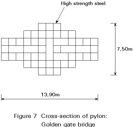
× high strength steel is used in the outer cells to carry the bending moments.
× a substantial part of the material is concentrated at the centre.
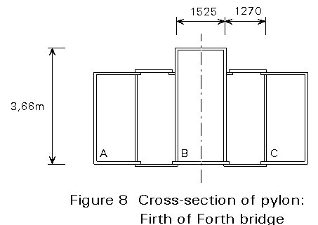
× three separate box sections, connected during erection.
× the material distribution is much better.
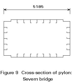
× all material is located in the right place, at the edges.
× the connections are designed to be completed from the inside.
× the dimensions are considerably reduced.
Concrete is the ideal material to carry compressive loads. Consequently it is natural to use concrete pylons. The Pont de Tancarville was the first suspension bridge with concrete pylons. Concrete pylons with heights of 250 m are used in the Great Belt East Bridge. However, in earthquake areas steel pylons are still preferred because of their capability for energy dissipation.
It should be considered that there are many factors influencing the choice of the material for pylons, e.g. soil conditions, speed of erection, stability during their construction, etc. Therefore, the choice should not be based entirely on a quantity-based cost estimate.
The choice of the cross-section for the stiffening girder is a very important step, since this influences the behaviour of the total structural system.
The developments in girder design have been closely connected to the development of calculation methods, in particular the deflection theory which is especially relevant for lighter girders.
A clear difference between flexural and torsional frequencies is required. Since 1960 this difference has in many cases been obtained by making the girder a box girder:
A serious draw-back of suspension bridges is their relatively large flexibility. For a long time it was accepted that the deformations of suspension bridges were too large for railway traffic. This view has more recently been completely abandoned. In Japan suspension bridges have been built with spans of more than 1000m, with two railway tracks (that can later be increased to four) at bottom chord level and four roadway lanes on top.
The main cable force is composed of two components, the vertical trying to lift the anchor block, and the horizontal trying to pull the anchor block towards the centre of the bridge.
The method of anchoring the main cable depends largely on the local soil conditions.
Two basic solutions are:
The anchorage is firmly connected to the surrounding rock.
The anchorage is almost entirely based on gravity.
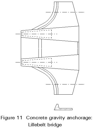
In gravity anchorages equilibrium between the cable force and soil pressure has to be carefully considered during erection.
During erection the vertical component of the cable force increases, exerting a vertical lifting force on the anchorage.
In order to limit the variations in soil pressure it might prove advantageous to increase the mass of the anchorage in pace with the erection. This procedure reduces subsidence problems and could make the construction, in particular the foundation, cheaper.
Due to temperature expansion a bridge with a continuous stiffening girder is subject to an elongation over the full length. This expansion has detrimental effects on the short hangers near the anchorages, see Figure 12.
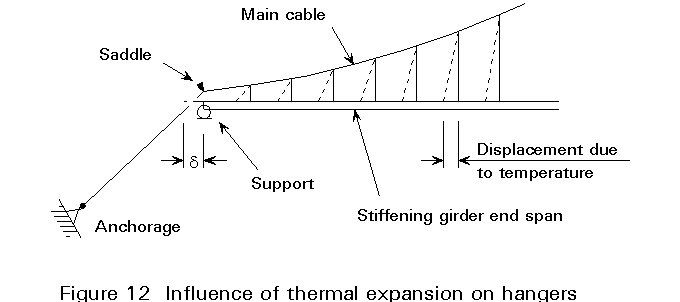
An upper value for the change in axial stress in a short hanger can be determined by the following calculation:
Length of the hanger H = 3000mm
Youngs modulus of the hanger E = 1,7 x 10⁵N/mm2
Girder length L = 1200m
Difference in temperature Dt = 15°C
Expansion coefficient a = 11 ´ 106
With these values the displacement, d, on one side becomes:
d
= 0,5 x a x Dt x L = 0,5 x 15 x 1200000 x 11.106 = 144mmAssuming (on the safe side) that the vertical distance between the hanger ends remains constant, the following results are obtained:
Elongation (DH) = ![]() , and
, and
Stress (s) = ![]()
In modern bridges with slender stiffening girders the assumption of a constant vertical distance is unrealistic, and the stress increase is therefore considerably smaller than determined above.
Aerodynamic excitation of the superstructure of any type of long-span bridge, but particularly of suspension bridges, may cause unacceptable oscillations. Five distinct forms of excitation may occur:
a. Vortex excitation.
b. Galloping.
c. Classical flutter.
d. Stall flutter.
e. Gust response.
In addition, a quasi-static aerodynamic instability known as divergence may occur.
Design against these effects requires specialised expertise and cannot be considered fully in this lecture. However some of them will be described briefly to give some knowledge of what has to be considered.
a. Vortex Excitation
When wind flows past a bridge deck, vortices are shed alternately from the upper and lower surface thus creating an alternating differential pressure and hence force on the bridge. The frequency of vortex shedding (Figure 13) is proportional to the wind speed, and the strength and regularity depend on the cross-section shape. If the frequency of shedding coincides with a natural frequency of the bridge, there is a risk of a resonant oscillation occurring.
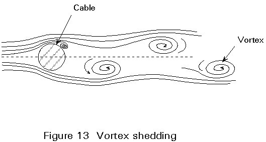
Irregular sections, such as trusses, are rarely prone to vortex excitation. The excitation even of regular sections is very seldom strong enough to cause large amplitudes. The amplitude is inversely proportional to the structural damping, and thus adding damping can always be a cure.
b. Classical Flutter
Classical flutter is another serious aerodynamic phenomenon, in which vertical and torsional oscillations are coupled and the lift moment on a moving cross-section reinforces the movement. It is a well known phenomenon of flight control surfaces in aircraft. It is amenable to mathematical analysis for plate-like structures (the streamlined boxes of the Severn Bridge type are nearly plate-like).
It is probably true to say that any section whose torsional frequency is higher than its bending frequency will eventually flutter. The important objective is to ensure that this effect occurs at a wind speed substantially higher than expected to occur in the actual location. The further apart the bending and torsional frequencies, the higher the wind speed causing flutter. The box sections of suspension bridges are very good in this respect, since the frequencies are separated by a factor of about 3.
The situation becomes worse, however, with longer spans. The Great Belt East Bridge is close to the maximum span for which the simple streamlined box cross-section will remain safe from classical flutter. Furthermore, in areas of tropical storms with very high wind speeds, special measures are required. Like galloping, classical flutter is destructive and not particularly sensitive to added damping.
Normally it is the fundamental modes which are coupled. However in the first Tacoma Narrows Bridge, there was a coupling of higher modes in a flutter-like oscillation. Sometimes asymmetric modes can be suppressed by using a central tie between the cable and deck at midspan. This tie stops the longitudinal cable movement associated with such modes. However very large forces occur in the tie, so special care has to be taken when designing the connections.
Truss-type suspension bridges are not necessarily safe from classical flutter, since the roadway deck is like a plate. They can be improved by leaving open slots between the carriageways to allow air to pass through, or by having permeable grillages within the carriageways themselves.
c. Structural Precautions
× For the closed box section a streamlined shape is simulated as close as possible giving the additional advantage of reducing the drag coefficient. The problem is now removed as far as the bridge is concerned. However, the traffic on the bridge can be subjected to stronger side winds.
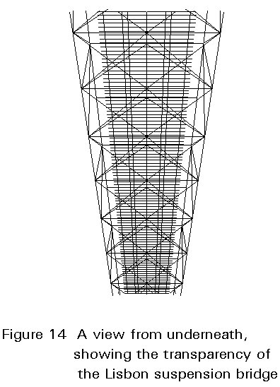
× For an open lattice box girder, some precautions are aimed at a disturbance of the vortices:
× the deck is constructed to make the wind pass through openings.
× a part of the deck is built with grids (Figure 14).
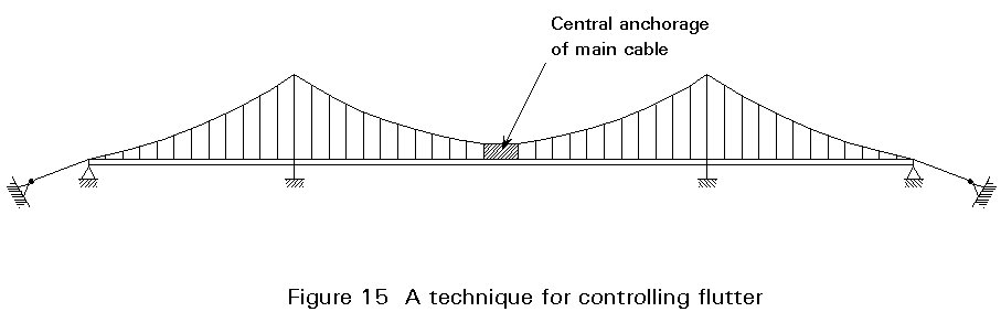
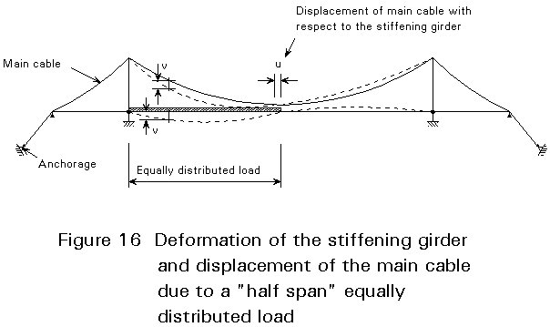
A very effective method is a tight connection between the cable and main girder at midspan (Figure 15).
Due to the torsional vibration mode, there is a considerable horizontal displacement of the main cable. This displacement, and consequently the torsional mode, is hampered effectively by clamping (Figure 16).
The suspension bridge has little rigidity of its own. In fact deflections have an influence which must be considered in the analysis. The problem is to determine what bending moments occur, taking deformations into account.
This problem was solved by Ritter in 1877, and confirmed by Melan in 1888, with the deflection theory. This theory was first used by Moisseiff in 1908 in the design of the Manhattan Suspension Bridge. Since that time it has become the classical method of suspension bridge analysis, after some developments by Steinman, Timoshenko, etc.
The main assumptions of this theory were:
(b) Their spacing is infinitely small, i.e. they form a continuous sheet between the cable and the girder.
Using these assumptions, the differential equation for live load-deflections in the deformed states could be obtained and the whole problem solved. In the analysis, dynamic terms also had to be inserted to compute frequencies.
Today the calculations are based on finite element programs that can include large deformations and the associated non-linear effects. With these programs most of the classical assumptions listed above can be omitted.
Socketed hangers connect the main cable and girder.
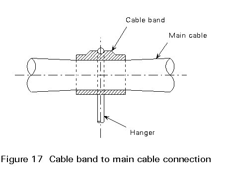
The hanger is connected to the main cable via a cable band consisting of two semi-cylindrical halves, connected together by high tensile steel bolts to develop the necessary friction. The hanger is connected to this cable band via a pin connection or it may be looped over the cable band.
The cable bands are firmly tightened onto the main cable and get their load carrying resistance mainly from friction and compression of the cable (Figure 17). The cable bands are carefully machined, taking into account an air void of approximately 20% in the cable.
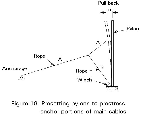
The main cable is subject to an axial loading that increases during erection of the bridge. The elongation of the cable from the anchor block to the pylon should be taken into account, e.g. by giving the pylons a pull-back (Figure 18).
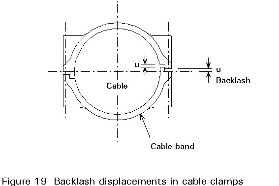
For the cable bands, the transverse contraction of the cable section is of the utmost importance. It causes the friction between cable band and cable to decrease and, as a result, the load carrying resistance goes down. Precautions should be taken to measure the relaxation and to tighten the bolts during erection, e.g. by making a backlash (Figure 19). For reasons of maintenance, the remaining gap is filled with rubber. In view of the contraction, the cable wrapping should be carried out after the bridge carries almost all of its full dead load.
Vertical hangers are usual. For a period of about 15 years inclined hangers were popular (Figure 20). The use of inclined hangers started with the Severn Bridge (1966) and was concluded with the Humber Bridge (1981).
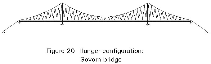
The idea was to make the bridge more rigid (» 25%), due to the truss behaviour, and to reduce the tendency to oscillate (flutter). The aim was to increase damping by utilizing the hysteresis of the spiral wires forming the hangers. However, the constantly changing forces in the hangers can create fatigue problems, and this is one of the reasons why designers returned to apply vertical hangers only.
The dead load of the girder and the cable systems can be carried entirely by the main cable provided that this will have a configuration coinciding with the funicular curve of the applied load.
This favourable transmission of dead load is achieved during erection of the bridge. The anchorage, the towers, the cables, the cable bands and the hangers are erected, in sequence.
The erection of the girder follows and is usually performed by:
As the sections of the girder behave like concentrated loads, the deflection of the main cable is large and the sections show openings at the bottom (Figure 21).
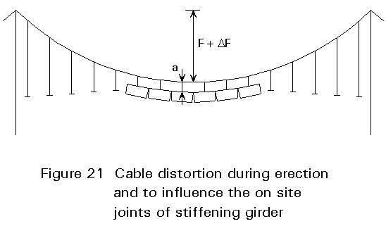
As the erection continues these openings close and finally openings on the top side of the girder appear. This is due to the fact that the girder is lighter during erection than in its serviceability condition, e.g. the wearing surface is missing.
After having erected a little over half of all sections, the final connections are usually made.
In the erection stage aerodynamic oscillations may also occur. Therefore temporary erection stages also have to be tested in a wind tunnel. Special devices to meet these problems have in some cases been required, e.g. in the girder of the Humber Bridge.