ESDEP WG 15B
STRUCTURAL SYSTEMS: BRIDGES
To introduce the design of plate girder and beam bridges for highway, railway and footbridge applications.
None
Lecture 8.4.1: Plate Girder Behaviour and Design I
Lecture 8.4.2: Plate Girder Behaviour and Design II
Lecture 8.4.3: Plate Girder Design - Special Topics
Lecture 15B.1: Conceptual Choice
Lecture 15B.2: Actions on Bridges
Lecture 15B.3: Bridge Decks
Lecture 15B.10: Bridge Equipment
Lecture 15B.11: Splices and other Connections in Bridges
Lecture 15B.12: Introduction to Bridge Construction
This lecture identifies the principal types of composite and non-composite plate girder bridges that are used for highway, railway and pedestrian bridges. It discusses overall layouts, types of continuity, girder proportions, longitudinal and cross girder spacings and choice of deck slabs. It gives guidance for initial sizing of the most popular forms of construction. It discusses the means by which girders can be stabilised against lateral-torsional and distortional buckling. It offers guidance for detailed design from global analysis to important details.
The simple beam is perhaps the most basic though not necessarily the most efficient form of bridging member. Unlike the arch, the beam supports applied loads primarily in flexure and associated shear. The distribution of material within the beam or plate girder cross-section is carefully selected to meet this requirement: material required to carry bending stresses is located at the upper and lower extremities of the cross-section for maximum efficiency, whilst the (usually deep) web panel separating the flanges is normally assumed to resist the full shear load applied to the section.
Depending on the spans involved, the loading intensity, costs of steelwork fabrication and any particular geometric and/or aesthetic requirements of the structure, a decision must be taken as to whether commercially available rolled beam sections or fabricated girders are to be used.
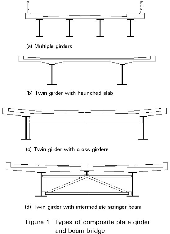
Plate girders and beams are utilised in a range of bridge forms [1-4]. Figure 1 shows the basic types of composite bridges. In Figure 1a the closely spaced main girders directly support a deck of uniform thickness. This form of construction is very simple and is widely used. However, its economy is reduced because there is much more shear capacity than is required, i.e. there are too many webs. If the webs are reduced in thickness so that they are more highly stressed they will require considerable, expensive stiffening.
In Figure 1b the economy in shear has improved considerably because there are only two girders, the minimum number possible. These are now much more widely spaced, and the slab will usually be haunched to provide sufficient transverse bending resistance.
At larger girder spacings the required slab thickness is increased beyond its economic limit. Cross girders are therefore introduced, as shown in Figure 1c. There is effectively no upper limit to the width of this form of construction.
As an intermediate solution the twin girders with intermediate stringer cross-section shown in Figure 1d has also been developed. The presence of the stringer reduces the slab support spacing to that for multiple girder bridges. The stringer, much shallower than the main beams, has to be supported by robust cross bracing. The longitudinal shear resistance from the two main girders is now limited to the minimum required. However this system does require substantial cross-bracing which considerably reduces the overall economy.
Non-composite bridges can adopt any of the structural forms shown in Figure 1 with the concrete slab replaced by an orthotropic steel deck. Such structures can only be justified where there is an overriding need to minimise the structural weight.
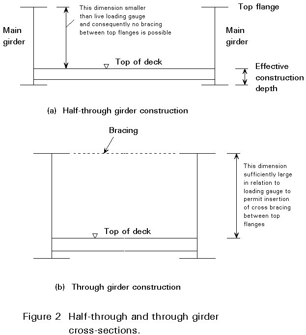
More commonly non-composite plate girders are used for the half-through or through girder bridges shown in Figure 2. The deck may either be concrete, supported by and usually acting compositely with steel cross-girders, or orthotropically stiffened steel.
Composite girder bridges are primarily used for highway or footbridges. Non-composite steel plate girder and beam bridges can be used to carry highway, railway or pedestrian loadings. One of the more specialist applications is in the design of ramps for access to roll-on/roll-off ferries.
Composite bridges with Universal Beams can span up to 30 m for simple spans and up to 35 m for continuous construction. However, Universal Beams can only be used for spans close to the upper end of these ranges if girder spacings are reduced considerably. In many such cases it will be more economic to use plate girders.
Composite plate girders can be used for the great majority of medium span bridges. When spans exceed 80 to 100 m it is likely that box girders will be favoured, because of their improved torsional aerodynamic and aesthetic properties.
Non composite girders can be used for spans between 20 and 100 m.
It is necessary to define the terms "through girder" and "half-through girder" bridges. These terms are common in the United Kingdom but appear to have no direct equivalents in many other countries. Figure 2 shows these two cross-section types and defines the essential difference between them. Two important points should be noted:
For plate girder and beam bridges, therefore, it is possible to say that the through girder form will not be encountered in structures carrying highway or railway traffic.
All girder bridges can be used for the range of longitudinal arrangements shown in Figure 3. For viaducts, the most economic arrangement is one in which all internal spans are of equal length L and the two end spans are each approximately of length 0,8L. Clearly, specific constraints imposed by the particular bridge site may prevent the use of such an arrangement.
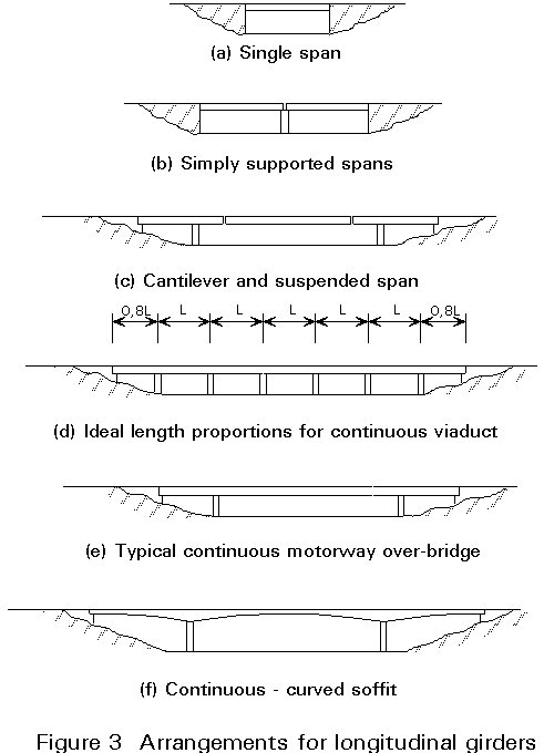
The use of a continuous girder rather than a number of simply supported girders on a multiple span structure will prove to be more efficient structurally and generally therefore also more economic. There is also a potential saving arising from the reduced number of deck joints required. Fewer deck joints give a longer term saving in maintenance costs as the need for repair to both the superstructure and pier heads at intermediate pier positions as a result of leakage through failed deck joints is reduced or entirely eliminated.
The use of cantilever and suspended span construction results in a determinate structure for which the global analysis is straightforward. As in the case of multiple simply supported spans, the cantilever and suspended span configuration can prove attractive where there is a likelihood of significant differential settlement between supports, e.g. in areas of mining subsidence. However, the need for both half joints in the main girders at points of support of the suspended spans and deck joints at these same locations results in increased long term maintenance costs (for similar reasons to those discussed in the previous paragraph).
Figure 4 shows the span-to-depth ratios that experience has demonstrated are likely to be the most economical for various types of girders. It is of course possible to adopt shallower construction to meet the constraints of a particular site but the weight and cost of the superstructure will thereby increase.
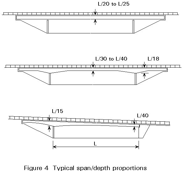
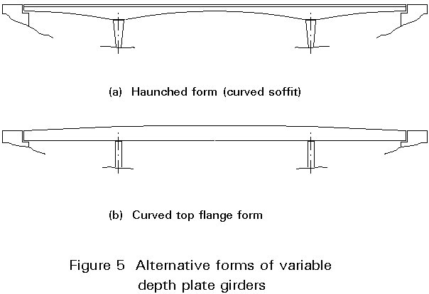
Figure 5 shows the two alternative ways of varying the depth of plate girders. The haunches of Figure 5a are most suitable for arrangements where the deck is above the main girders. Figure 5b shows the arrangement that is more suitable for half-through and through bridges.
The deck slab has to distribute wheel loads to the main girders and also to transfer some load from more highly loaded girders to adjacent ones. The spacing of main girders thus affects the design of the slab as well as the number of girders required.
For closely spaced girders, wheel loads determine the design of the slab including its reinforcement. The minimum thickness of slab is about 220 mm, on the basis of typical shear and crack width requirements. The total transverse moments in the slab are not very sensitive to girder spacing in the range 2,5 to 3,8 m because the increase in local moments as the spacing increases is almost balanced by the reduction in moments from the transfer of load between girders. The optimum slab thickness is typically 230 - 250 mm.
In selecting a suitable girder spacing, it is important to ensure that the cantilevers at the edges of the slab are limited to avoid overstressing the slab or forcing too much load onto the outer girders.
From the preceding discussion the following proportions for the cross-section in Figure 1a naturally emerge:
This form of construction has proved to be economic for shorter span composite bridges. It is used throughout Europe for spans up to about 35 m. In the UK it is regularly used for spans up to around 60 m and exceptionally up to 100 m. At the longer spans economy has been achieved because the market for major plate girders has been met by specialist fabricators who have invested in semi-automatic fabrication lines.
Elsewhere in Europe the cross-section shown in Figure 1b has generally been adopted for structures of modest width, up to 12 m, and spans of over 35 m. The slab is usually of greater, and variable depth to allow the girder spacing to increase. Typical proportions are:
Where the bridge is wider than about 12 m, it is usual to introduce cross girders as shown in Figure 1c. It follows from the earlier discussions that the optimum proportions are:
Experience and a few empirical rules can be used for the approximate analysis that precedes the initial selection of sizes. The following illustrates the process for a multi-girder bridge. Further guidance can be found in [5].
Governing shear occurs when the design "heavy vehicle" is placed directly over a girder adjacent to a support. If the girder is an edge girder, approximately 85% of the total shear will be carried by the girder under consideration. If it is an internal girder a more appropriate proportion is 70%.
Governing moments usually occur when the design "heavy vehicle" is directly over the girder at midspan. Approximately 75% of the vehicle is carried by an edge girder; for an internal girder the proportion is approximately 50%. Simple moment distribution or other manual method of analysis will give realistic estimates of support and midspan moments.
Most designers size the web first so that it can carry 150% of the governing shear (the reserve is valuable in contributing to bending resistance). If the bottom flange is inclined, it will carry some of the shear, and the web can be reduced in thickness accordingly. For girders up to 1,5 m depth, including rolled sections, the web is usually proportioned so that it does not require any stiffening except at supports. In the range 1,5 to 2,5 m the optimum web is likely to require vertical stiffening possibly with horizontal stiffening near internal supports where more of the web is in compression. Above 2,5 m it is likely to require both vertical and horizonal stiffening.
The bottom flange is sized next to provide the required modulus. Consistent with the availability of standard plates and flats, it is usually made as wide as possible within codified limits on outstands. These proportions give the highest possible lateral inertia to the girder, minimising bracing requirements and assisting stability during erection.
At internal supports the top flange is usually made half the area of the bottom, additional tensile resistance being provided by slab reinforcement.
At midspan the top flange should only be reduced to 50% of the bottom if this does not increase instability problems during erection. It will often be necessary to increase the top flange size for the construction condition.
Clean lines to the overall appearance and minimum use of complex details are most likely to lead to an economic and efficient bridge structure, though external constraints often compromise selection of the best structural solution.
The fabrication of the basic I-section is not particularly expensive, especially with the use of modern semi-automatic girder welding machines (T and I machines). It is of the same order of cost as the material used. With the widespread use of computers in CAD and in control of fabrication shop machines, geometrical variations, such as curved soffits, varying superelevation and precambering, can be readily achieved with almost no cost penalty. Much of the total cost of fabrication is incurred in the addition of stiffeners, the fabrication of bracing members, butt welding, the attachment of ancillary items, and other local detailing which leads to a significant manual input to the process. The designer can thus exercise freedom in his choice of overall arrangement but should try to minimise the number of 'small pieces' which must be dealt with during the fabrication process.
The use of wide flats for flanges eliminates a cutting-out operation from the fabrication process, thus reducing costs. The rolled edge to the flat is to be preferred over the sharper flame-cut edge. It also allows the use of automatic saw-and-drill machinery for cutting to length, drilling of the holes and marking of shear stud positions. The rolling tolerances of wide flats have recently been brought into line with those of plates, and this makes them an attractive option for flanges. It is recommended that designs be tailored to permit their use, though some fabricators will still prefer to cut from plate, on account of the very good tolerances on width and straightness achieved with modern cutting equipment, which suits girder welding machines.
Expert advice should be obtained from fabricators to assist in the choice of details at an early stage in the design. Most fabricators welcome approaches from designers and respond helpfully to any interest shown in their fabrication methods.
The form of the substructure at intermediate supports, whether for reasons of appearance or of construction, often has a strong influence on the form of the superstructure. For example, a low clearance bridge over poor ground might use multiple main girders on a single broad pier, whereas a high level bridge of the same deck width and span over good ground might use twin main girders, with cross girders, on individual columns.
Highly skewed bridges are sometimes unavoidable, but it should be noted that the high skew leads to the need for a greater design effort, more difficult fabrication and more complex erection procedures. In particular, the analytical model, the detailing of abutment trimmer beams, precambering and relative deflection between main beams must all be considered carefully.
Construction of a composite bridge superstructure usually proceeds by the sequential erection of the pieces of the main girders, usually working from one end to the other, followed by concreting of the deck slab and removal of falsework. However, situations vary considerably and the constraints on access will be a major influence on the erection sequence for any bridge. In some cases they might determine the form of the bridge. Before proceeding to detailed design, at least one erection scheme should be considered, and the requirements for it included in the detailed design.
In some circumstances, where access from below is difficult or impossible, launching from one or both ends may be appropriate. If so, this is likely to have a significant effect on girder arrangements and detailing. Advice should be sought from an experienced contractor.
Stability of girders during erection and under the weight of wet concrete will have a significant effect on the size and bracing of the top flange in midspan regions. Temporary bowstring bracing to individual girders may need to be provided if they are too heavy to be erected as pairs.
Site splices between the main girder sections are commonly connected with high strength friction grip (HSFG) bolts. Welded joints are more expensive and prove more onerous on quality control on a small job but should be considered on larger jobs and where their better appearance is warranted. One method or the other should be adopted throughout the bridge; it is uneconomic to use both methods.
Figure 6 shows the basic types of cross-section for non-composite plate girder bridges.
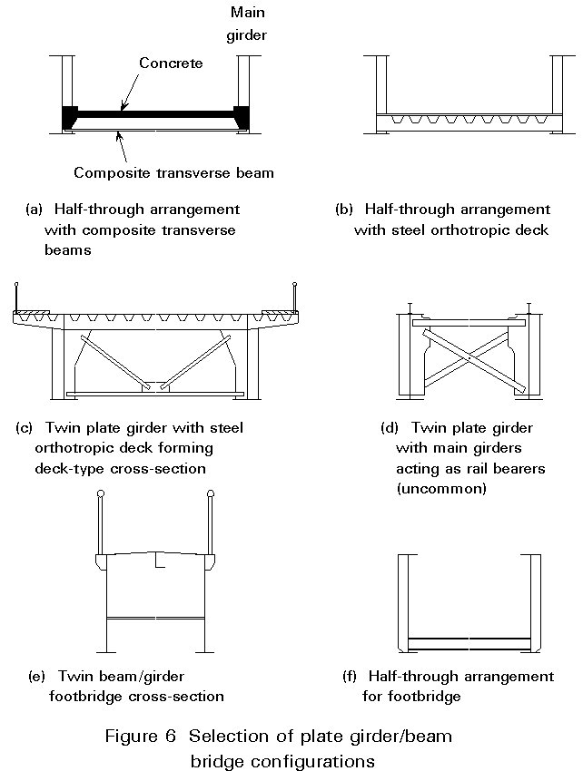
If minimum construction depth is required either for aesthetic or economic reasons, the half-through cross-section, e.g. Figures 6a, 6b and 6f, will be the most appropriate solution for highway, railway or footbridges. This arrangement is commonly used in railway bridges where even maximum permissible approach gradients for the track are very small and where the minimum effective construction depth (Figure 2a) afforded by the half-through arrangement is important to minimise the cost of earthworks and land purchase on the approaches to the bridge. The half-through form does however have important implications for compression flange stability. These implications are discussed in greater detail in Section 5.
If construction depth is unlimited then a deck-type cross-section as shown in Figure 6c can be considered. It must be stated, however, that the use of a steel/concrete composite girder deck is generally much more economic than the orthotropic deck arrangement shown in Figure 6c. Only where minimum weight is the overriding design consideration will the orthotropic deck be an attractive solution.
An open grid steel deck arrangement for a railway structure results in a cross-section as shown in Figure 6d or a variant of this. The open deck form is however now almost unused for new railway structures in Europe particularly because ballast is used on nearly all modern railway structures and therefore some form of "closed" deck is required for ballast retention. In this "open" arrangement the main girders also act as rail bearers. One variant, discussed in greater detail in Section 5, is that in which the rails are supported on longitudinal stringers, themselves rigidly connected to flexurally stiff cross girders spanning between the two main girders. For all but the shortest spans this form of construction would almost certainly demand some form of wind bracing in plan as, unlike the previous cases, there is no deck plate to provide a horizontal diaphragm. Such plan bracing would be connected directly to the main girders.
The use of fabricated girders rather than rolled beam sections for the two main girders gives the designer freedom to select the most economical girder cross-section for the structure. However, where spans are relatively short and/or live loading intensity is low, rolled sections of suitable proportions are normally available.
Where parallel flanged main girders are used, i.e. where overall depth of girder remains approximately constant over the full span, a more interesting appearance can often be obtained by the introduction of a noticeable degree of precamber. The degree of precamber which will be visually and geometrically acceptable in any particular situation depends on the nature of the crossing, e.g. road, rail or pedestrian traffic, and the interaction of the structural form with its surroundings.
Variable depth plate girders offer considerably more scope for a satisfactory final appearance. Clearly, however, they demand the use of fabricated rather than rolled beam sections. Deepening of the girder at intermediate support positions by the introduction of a curved soffit profile (Figure 5a) is one method of achieving varying depth. It should be noted however that a half-through arrangement combined with this form of haunched main girder is impracticable.
An alternative form of variable depth girder is one in which the lower flange remains almost horizontal in the final profile whilst the upper flange is gently curved in elevation with maximum overall girder depth occurring at midspan on the central span. An example of this form is shown in Figure 5b. This arrangement can readily be used in conjunction with the half-through form. It is probably fair to conclude that a variable depth girder of this type provides more satisfactory appearance in a multiple than in a single span configuration.
Some rolled beam sections and almost all plate girders of normal proportions require some form of web stiffening (either transverse or longitudinal or both). The functions of the various types of stiffeners are described in Lecture 8.4.3. The attachment of intermediate stiffeners to the exposed outer faces of the girders is often avoided for aesthetic reasons, although there may be little alternative to the provision of bearing stiffeners on both sides of the web at support positions.
Where bending moments increase to the extent that local thickening of flanges is required, the thickening can be achieved either by the attachment of flange cover plates or by the use of tapered plates. The latter, where required, have traditionally been machined from flat plate; however, tapered plates are now commercially available from some steel producers.
Three basic forms of deck [7] are shown in Figure 6: orthotropic (Figure 6c), modified filler beam (or composite transverse beams) (Figure 6a), and the steel plate type (Figure 6e). Of these three types, the orthotropic deck although lightweight, is the most expensive whilst the basic steel plate is only generally suitable for use in footbridges. Subsequent maintenance costs will also be greatest for the orthotropic deck.
Where the diaphragm action provided by an orthotropic deck or modified filler beam deck is used to provide resistance to transverse loads, e.g. wind, any resulting additional stresses must be allowed for in the design.
The use of permanent soffit formwork in the case of the composite transverse or modified filler beam deck can speed construction. This possibility is of particular importance in bridge construction or replacement over railway tracks or busy motorways.
Other aspects of these and other bridge deck types are discussed in Lecture 15B.3.
Initial estimates of main girder proportions are generally made on the basis of experience or rules of thumb such as those given below. Such estimates of girder size then permit better estimates of dead load of the structure to be calculated. Additional guidance on proportioning plate girders is given in Lecture 8.4.1.
For highway and railway bridges, common proportions for main girders (where Lo is the length between points of zero moment) are:
Overall depth, h:
Lo/18 £ h £ Lo/12 (highway)
Lo/10 £ h £ Lo/7 (railway)
flange width, b: 0,25h £ b £ 0,35h
flange thickness, tf: b/25 £ tf £ b/10
web thickness, tw: tw » h/125
These values should be regarded as indicative only.
Assuming the web carries approximately 20% of the factored bending moment, M, then a better approximation of the required flange cross-section area may be determined from:
Af = ![]() ,
,
although it must be noted that the value of s used will be dependent on girder effective length; consequently, an estimate of s must be made which reflects the degree of restraint provided to the main girder.
Refinements are then carried out as part of the detailed design process to maximise girder efficiency whilst also satisfying any other stability, stiffener, fatigue or dynamic criteria which may be relevant.
In terms of final cost, it is frequently more important to design a girder for minimum labour input rather than for minimum steel tonnage (or at least to swing the balance in this direction). For example, the labour costs associated with fabrication of stiffeners for a highly stiffened, thin web plate are often considerably greater than the additional cost of material associated with the provision of a thicker, more lightly stiffened web. The usual solution is generally a compromise between minimum labour input and minimum tonnage.
Plate girders have a very low torsional stiffness and a very high ratio of major axis to minor axis second moment of area [1-3]. Thus, when bent about their major axis, they are very prone to lateral-torsional instability, Figure 7a. Adequate resistance to such instability has to be provided during construction.
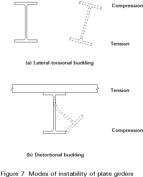
In the completed structure one flange is usually stabilised by the deck. If the unrestrained flange is in compression, distortional buckling, Figure 7b, is a possible mode of failure and has to be adequately considered in design.
Figure 8 summarises the types of bracing and other forms of transverse structure that are commonly found within composite plate girder bridges. Figure 9 shows some typical arrangements of bracing systems.
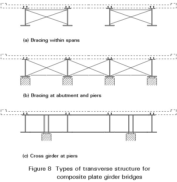
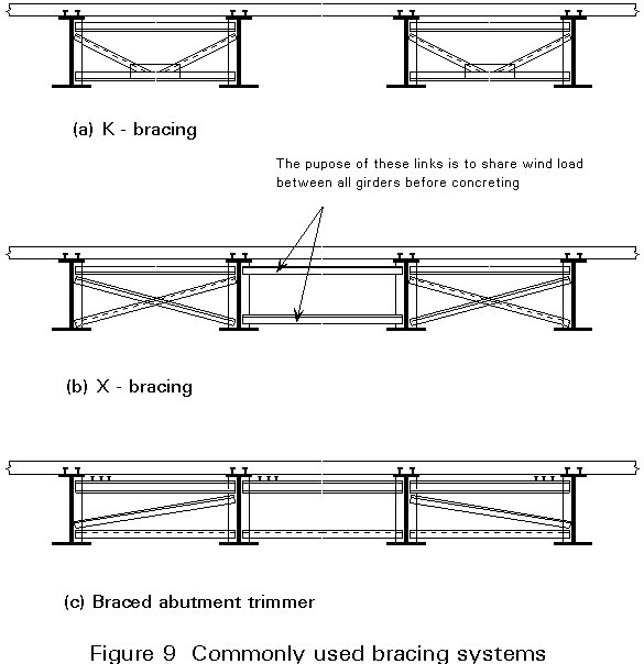
Within a span the most convenient form of stabilising bracing is torsional bracing, Figure 8a. Not less than three such bracing lines are usually placed in each span, Figure 9a and b showing typical arrangements. The convenience of this form of bracing primarily arises because of the simple way that it ties two girders together into a stable subassembly. Given adequate cranage this subassembly can be assembled on the ground and lifted into position by a single operation. By tying pairs of girders together in this way their torsional displacements are suppressed and therefore, providing the system is sufficiently stiff, lateral-torsional buckling of the overall girders is prevented during construction. In the completed structure the concrete slab, restraining the top flange, prevents any instability in positive bending. For regions near internal supports and subject to negative moments, the bottom flange continues to need restraint (now against distortional buckling rather than lateral-torsional buckling). This restraint is effectively provided by torsional bracing. [Note that for shorter span structures, even when account is properly taken of pattern loading effects, the length of bottom flange in compression is usually so short that no such bracing is required for the completed structure. Where the web is stocky inverted U-frame action can be mobilised to assist with negative moment stability.] Modern practice is usually just to tie pairs of girders together as shown in Figure 9a. The discontinuity in the transverse bracing ensures that it affords low overall transverse bending distribution in the completed structure. Where full transverse bracing is provided it attracts considerable, and fully reversing, loads both to itself and the stiffeners to which it is attached. Such elements are therefore prone to fatigue damage. (There have been several such failures in North America.) Where discontinuous temporary bracing is used it may be safely left in for the service life of the structure; if continuous bracing is adopted it must be recognised that it will participate significantly in the structural behaviour of the completed bridge. It should either be designed accordingly for fatigue or removed after construction.
Plan bracing may also be provided near the top flange for the construction condition, Figure 7a. However, it is likely to interfere with the slab construction and is of negligible benefit in stabilising negative moment regions.
Plan bracing may sometimes be required in the completed structure near the bottom flange, Figure 8a. It may be used just near internal supports to stabilise the bottom flange in compression. It may also be needed in more major structures which could be prone to aerodynamic instability. One way of preventing such instability (flutter) is to separate the torsional and vertical natural frequencies of the structure. Lower flange plan bracing, effectively turning the pairs of plate girders into cells, increases the torsional stiffness sufficiently to achieve the desired effect.
At most supports there are separate columns for each girder, Figure 8b, or all the girders sit on a substructure cross head. In such cases, support bracing is required to:
Where it is not possible to provide direct support to each longitudinal girder, as shown in Figure 8c, a cross girder is required to transfer the girder vertical reactions to the supports. It clearly also will provide the bracing functions outlined above.
Where the plate girders support the deck at or near the top flange, as shown in Figure 6c, d and e, considerations are broadly similar to the composite girders discussed in Section 5.2.
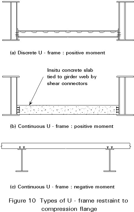
However, the half-through or through girder arrangements of Figure 6a, b and f cannot adopt any form of triangulated bracing because it would interfere with the bridge's function. The deck can usually be designed as a horizontal beam and provides translational restraint at its level but the flange remote from the deck can only be stabilised by using U-frame action.
The form of the U-frame action can either be continuous or discrete, depending on the form of the deck structure and the slenderness of the webs, as shown in Figure 10. The degree of restraint provided to the compression flange depends directly on the stiffness of the three main U-frame components: the transverse member, the two webs of the main girder (including any associated vertical stiffeners) and their connections. The effective length of a compression flange restrained by U-frame action is usually calculated by recourse to the theory of beams on elastic foundations [6], the elastic supports being provided by the U-frames.
The detailed design stage confirms or refines the outline design produced in the initial design stage. It is essentially a checking process, applying a complete range of loading conditions to a mathematical model to generate calculated forces and stresses at critical locations in the structure. These forces and stresses are then checked to see that they comply with the 'good practice' expressed in the code. The detail of the checking process is sufficiently thorough to enable working drawings to be prepared, in conjunction with a specification for workmanship and materials, and the bridge to be constructed.
A global analysis is required to establish the maximum forces and moments at the critical parts of the bridge, under the variety of possible loading conditions. Local analysis of the deck slab is usually treated separately from the global analysis; this is described in Lecture 15B.3.
It is now common practice to use a computer analysis, and this facility is assumed to be available to the designer. Programs are available over a wide range of sophistication and capability. The selection of program will usually depend on the designer's in-house computing facilities. However, for a structure as fundamentally simple as a beam-and-slab bridge, quite simple programs will usually suffice.
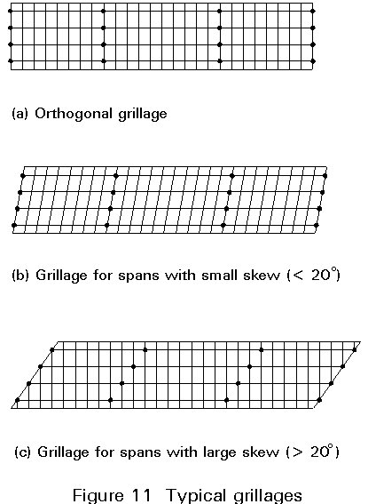
The basis of most commonly used computer models is the grillage analogy. In this model the structure is idealised as a number of longitudinal and transverse beam elements in a single plane, rigidly interconnected at nodes. Transverse beams may be orthogonal or skewed with respect to the longitudinal beams.
Each beam element represents either a composite section (e.g. main girder with associated slab) or a width of slab (e.g. a transverse element may represent a width of slab equal to the spacing of the transverse elements). Figure 11 shows examples of typical grillages.
Because many different load factors and combinations are involved in the assessment of design loads at several principal sections, it is usual for each load to be analysed separately and without load factors. Combination of appropriate factored load cases is then either performed manually - usually by presentation in tabular form - or, if the program allows, as a separate presentation of combined factored forces. Since so many separate load cases and factors are used to build up total figures, the designer is advised to include routine checks (such as totalling reactions) and to use tabular presentation of results to avoid errors. The graphical displays and printout provided now by analysis and spreadsheet software can also be recommended for checking results.
The object of the analysis is to arrive at design load effects for the various elements of the structure. The most severe selection of loadings and combinations needs to be determined for each critical element. The main design load effects which are to be calculated include the following:
In addition, displacements and rotations at bearings will need to be calculated.
The total deflections under dead and superimposed loads should be calculated so that the designer can indicate the dead load deflections on his drawings.
Selection of the most heavily loaded girder can usually be made by inspection, as can the selection of the more heavily loaded of intermediate supports. Influence lines can be used to identify appropriate loaded lengths of the maximum effects. If cross-sections vary within spans, or spans are unequal, then more cases will need to be analysed to determine load effects at the points of change or in each span.
The effects of differential temperature and shrinkage modified by creep are calculated in two parts. The first is an internal stress distribution, assuming that the beam is free to adopt any curvature that this produces (primary effects). The second is a set of moments and shears necessary to achieve continuity over a number of fixed supports. These moments and shears give rise to further longitudinal and shear stresses (secondary effects).
Detailed design of the plate girder is discussed in Lectures 8.4.
Detailed design of splices and other connections are discussed in Lecture 15B.11 and in Lectures 11.
Sections 6.4.1 and 6.4.2 describe situations in which additional stresses arise in longitudinal stringers and cross girders in steel open grid deck arrangements. Whilst the use of this type of deck is now uncommon in Europe for the reasons stated in Section 4.1, this form of construction nevertheless highlights two aspects which are of structural importance and which also serve to illustrate a broader structural principle.
It is assumed that twin longitudinal main girders are connected by relatively stiff cross girders at appropriate intervals; longitudinal stringers are assumed to be rigidly connected to these cross girders. For deck type railway structures the stringers would be located at the top of the section to act as rail bearers. This then gives rise to a mismatch in neutral axis levels between the main girders and stringers, Figure 12.
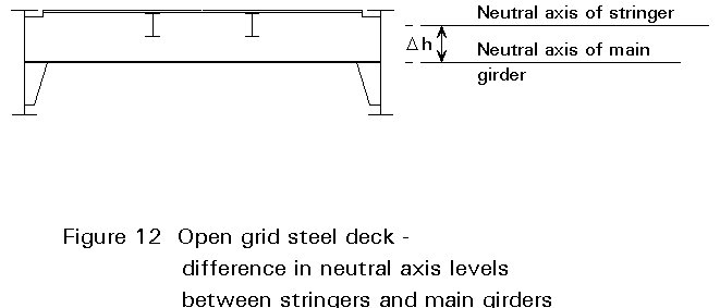
In the deck cross-section shown in Figure 12, Dh represents the difference in level between the neutral axes of the main girders and longitudinal stringers. The rigid connections between stringers and cross girders ensure that the curvature of the main girders is also imposed on the stringers. Expressing curvatures in terms of M/EI for each element and equating, leads to:
Mst = ![]()
where
Mst is the bending moment in the stringer
Mmg is the bending moment in the main girder
Ist is the second moment of area of the stringer
Img is the second moment of area of the main girder
Mst can be reduced by making the final connection of stringer to cross girder after the bridge carries its own dead load, thus ensuring that Mst arises purely from live load effects.
Assume f is the absolute value of the rotation (in the plane of loading) of the ends of the main girders at supports and Iy is the second moment of area of one flange of the cross girder with respect to the minor axis of the section. Neglecting second order effects, the lengths of the neutral axes of the stringers do not change (i.e. shortening is assumed to be negligible). The displaced arrangement is then as shown in Figure 13.
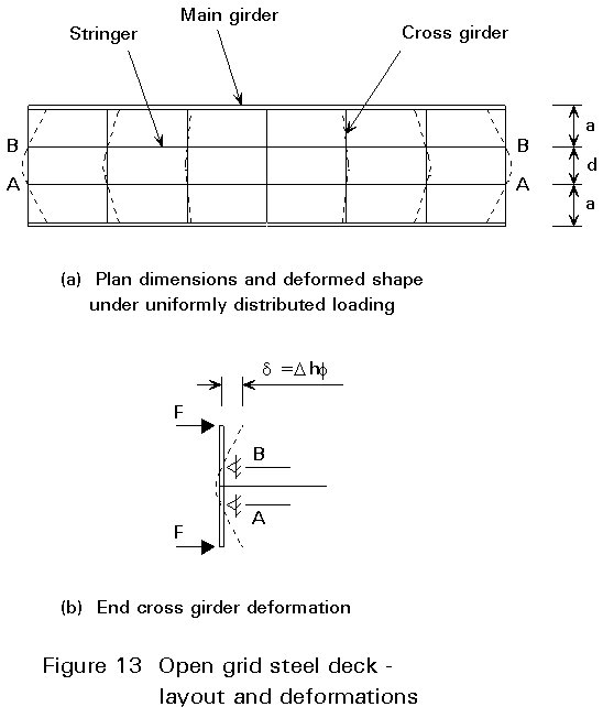
This displacement of the end of the top flange of the cross girder, Figure 13b, is approximately:
d
= Dh fAs the stringers suffer no shortening they serve as fixed supports to the cross girder flange and as a result this flange deforms in plan.
The displacement d can be assumed to be the result of application of a tip force F to the flange, the force-displacement relationship being:
d
=
in which a, d are the dimensions indicated in Figure 13a and Iy is the second moment of area of one flange of the cross girder with respect to the minor axis of the cross girder section.
The maximum bending stress in the cross girder flange arising from the above effect is therefore:
s
f =where b is the flange width of the cross girder.
The resulting bending stresses in the flange are not insignificant. This fact is demonstrated by an example in which the following values are assumed:
D
h = 600 mmf
= 0,003 radb = 300 mm
a = 1000 mm
d = 1500 mm,
giving
s
= 52 N/mm2Clearly the additional stress disappears when Dh = 0 and, although reducing b is beneficial, varying flange thickness theoretically has no effect. Reductions in transverse dimensions a and d have an adverse effect.
Composite multi-girder bridges
Composite twin girder bridges with haunched slabs or cross-girders
Half-through and through girder bridges.
[1] Iles, D. C., Design Guide for Simply Supported Composite Bridges, SCI Publication P084, 1991.
[2] Iles, D. C., Design Guide for Continuous Composite Bridges 1: Compact Sections, 2nd Edition, SCI Publication P065, 1993.
[3] Iles, D. C., Design Guide for Continuous Composite Bridges 2: Non-Compact Sections, 2nd Edition, SCI Publication P066, 1993.
[4] Foucriat, J. C., Actual Trends in French Road Bridge Design, Int Symp. Bridges in Steel, ECCS, Paris 1992.
[5] Owens, G. W. and Knowles, P. R. (ed) The Steel Designers Manual, 5th Edition 1992, Blackwell Scientific Publications, London.
[6] Hetényi, M., Beams of Elastic Foundations, University of Michigan Press 1946.
[7] Hambly, E. C., Bridge Deck Behaviour, Spon, London 1991.