ESDEP WG 15B
STRUCTURAL SYSTEMS: BRIDGES
To cover the planning and contractual procedures for bridge projects, together with methods of fabrication and erection.
None
Lecture 15B.1: Conceptual Choice
Lecture 15B.2: Actions on Bridges
Lecture 15B.3: Bridge Decks
Lecture 15B.4: Plate Girder and Beam Bridges
Lecture 15B.5: Truss Bridges
Lecture 15B.6: Box Girder Bridges
Lecture 15B.7: Arch Bridges
Lecture 15B.8: Cable Stayed Bridges
Lecture 15B.9: Suspension Bridges
Lecture 15B.11: Splices in Bridges
First the lecture discusses contractual procedures for bridge projects and gives some guidance on the choice of a tenderer as standard contractor.
Secondly, fabrication in the workshop and transportation from workshop to site are reviewed.
The main methods of erection of steel bridges are also briefly discussed.
A bridge carries a right of way or a utility over an obstacle such as a road or railway, a river or a valley.
The designer considers the nature and magnitude of the obstacle to be crossed in determining the form of construction and compares several alternatives to determine the optimum solution.
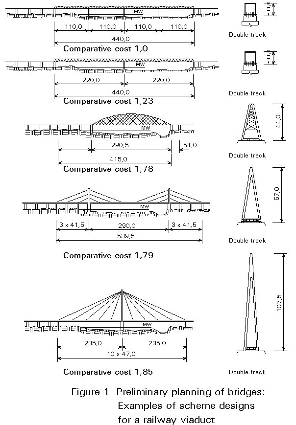
In some cases, such as important crossings of rivers or other obstacles, it is necessary to investigate several layouts (as illustrated in Figure 1). The final choice is made only after several competitive designs have been examined. Costs are not always the main basis in selecting the type of bridge. Functional, service and aesthetic requirements are also included in the selection of the type of structure.
This lecture covers planning and contractual procedures for bridge projects, together with methods of fabrication and erection of steel bridges.
A bridge is normally promoted by a major national or local government or quasi-government department, such as the Highways or Railways Department. Such bodies have national responsibility for planning infrastructure development and determining scheme priorities. A bridge may be a small part of such a scheme and thus have limited impact on broad policy issues, or it may be a major project by itself.
A Project Director appointed by the Promoter oversees planning of the project, including drawing up preliminary technical plans and cost budgets, making arrangements for public enquiries and compulsory purchase orders, and determining contract arrangements. His team may be drawn from the Promoter's staff, or he may appoint consulting engineers. He will subsequently oversee the detailed design and specification, followed by execution of the works. Detailed design and supervision may be carried out by a consulting engineer.
A number of decisions on the contract arrangements have to be made at an early stage; for example, will contractors be invited to tender for a fully designed and specified scheme, or on the basis of a performance specification with the contractors responsible for the detailed design? Will the contractor be paid by the promoter for work done, or will he finance the construction himself and recover his costs and profits from operating the project?
For major bridges, an Independent Supervisor is advisable. His role is to check the structure from the design through to the erection, and may include also settling disputes between the designer and the constructor, etc.
Tender procedures vary; the following are typical:
In comparing costs of different types of bridge all relevant aspects must be considered. For example, some of the saving that a steel bridge offers over concrete can come from cheaper foundations. The comparison should not be made on the basis of superstructure alone. It is also important to consider the full cost during the life of the structure, taking account of the maintenance which will be required.
The six major items in the construction cost of a steel bridge are:
Other possible costs to allow for are:
A contractor must be able to interpret the Promoter's requirements from the contract documents, to make and use accurate fabrication drawings, and to devise and execute a safe erection scheme. If the contract requires it, he must be able to work up the detailed design, possibly employing a consulting engineer. He must have satisfactory formal Quality Assurance and Safety procedures, and be able to respond to technical problems. Experience in building other bridges is also desirable.
For a major structure, the contractor may wish to retain specialist technical advice. Such an arrangement should not be seen as an admission of technical weakness, but as a responsible technical attitude.
A contractor must be capable of executing major works to a required timescale, and must have adequate progress control procedures. He must be able to react satisfactorily to emergencies such as prolonged inclement weather, failure of third parties to perform, etc.
Since a contractor who failed the performance criteria of technical ability and programme should not have been invited to tender, costs are likely to be the main basis of comparison of tenders. However, the Promoter will also need to consider, for example:
Methods of fabrication and erection of steel bridges are of prime importance to the designer and the contractor; whilst the details are normally the responsibility of the contractor, the designer must be aware of modern construction processes in order to produce an economic design.
Materials, fabrication and erection are interrelated. For example, the fabrication process often depends on the grade of steel used and can be profoundly affected by the location of the site and the method of erection.
National specifications date back to the early years of the 20th century, and have been updated continuously as the benefits of higher yield stress, weldability, low temperature toughness, improved corrosion resistance, etc, became apparent. In Europe this evolution has culminated in the issue of a common specification for structural steel, EN 10025, which gives mechanical and chemical properties for a wide range of grades.
As yield stress increases, so do problems of fabrication. Welds are more prone to defects such as Heat Affected Zone cracking. HAZ cracking can be avoided or minimized by adequate welding technology, for example, by careful choice of electrodes and possibly by pre-heating the parent metal near the weld.
Welding of steel causes locked-in stresses and/or distortions, both of which can reduce the strength of a bridge or its parts. If distortions are to be avoided, panels have to be restrained during welding. The higher the yield stress, the more severe are these effects.
The means of avoiding or rectifying such problems are within the expertise of an experienced fabricator, who will frequently set up special trials to determine the optimum procedure.
The effects of welding on the mechanical properties of steel are restricted to the Heat Affected Zone of the weld; however, weld failure usually occurs by fracture and hence may lead to total structural failure. Steel must therefore possess adequate weldability which may be defined as its ability to retain satisfactory characteristics in the Heat Affected Zone after welding. It is a function of the properties of both the parent steel and the welding consumables and procedures.
Parent steel complying with the requirements of EN 10025 may normally be assumed to be weldable, although this alone does not guarantee satisfactory welding (see the warning in 7.5.1.1).
Welding procedures are of primary importance. A welded connection can be detailed to minimize the locked-in stresses on cooling; this implies a minimum of restraint which could result in unacceptable distortion and thus is a compromise. It is the fabricator's duty to ensure that, irrespective of the design, he produces a satisfactory end product.
Sufficient ductility of the weld itself is obtained by using suitable electrodes which can, however, bring their own problems, particularly if used for manual welding. For example, low hydrogen electrodes must be baked before use and stored in special preheated quivers.
Preheating of the parent steel is often necessary to avoid cracking; it is more likely to be needed with thicker plates and higher steel grades. In recent years, automatic and semi-automatic welding machines have been introduced. These machines are capable of operating at speeds far in excess of those obtainable by manual methods (see 8.3).
Although codes give guidance on weld procedures and the type of electrode to use, it is still vital for the fabricator to carry out controlled procedure trials on specimens set up to represent the conditions which will exist in practice. Furthermore, welded connections must be subjected to comprehensive non-destructive testing, i.e. radiography and/or ultrasonic and other methods of crack detection.
Welding should be carried out only by appropriately qualified welders, under the supervision of qualified foremen. The welders must be periodically tested.
Bridge welding needs particular care; not only are service conditions very onerous, but site welding needs protection from the weather. Site welding can only be reliably carried out with adequate preparation, including:
Such arrangements can generally only be justified for major structures. In low temperatures preheat may be needed where it would have been unnecessary in a fabrication shop.
Access for welding should always be considered.
Inspection and testing of welding on site is always required.
A fabricator normally produces the highest quality work in a permanent fabrication shop, using experienced staff and high quality equipment. These facilities remove uncertainties due to weather, and allow the fabricator to plan his production efficiently and carry it out accurately. The facilities should therefore be arranged to fabricate as large sections as practicable in the works, leaving only the final erection and connection for site. Large sections can be trial erected in the works, although this is becoming unnecessary with the high accuracy obtained using numerically controlled fabrication equipment.
Transport by road and/or rail limits the maximum size of fabricated piece which can be moved from the shop but, if the layout and location of shop and site permit, very large bridge sections can be moved by water.
The fabricator receives the raw materials from his suppliers, fabricates them into the largest practicable pieces, and transports them to site for erection. His objective is to improve productivity by reducing production time and cost whilst maintaining or improving quality of fabrication. From his past records he should be able to optimise and improve his production by, for example:
Automation of fabrication of plate girders is becoming common, not only in individual machines, but by setting up production lines so that processes follow each other in an efficient sequence with a minimum of manual handling. The ultimate objective is to link computer aided design and detailing (CAD) to computer aided manufacturing (CAM).
The fabricator has to convert the designer's drawings into fabrication drawings. This conversion involves working out cutting sizes (allowing for dead load deflections of the bridge, welding shrinkage, etc.), and fully detailing all connections. Many operations have already been largely automated in some modern fabrication shops:
Maximum benefits for CAD/CAM can only be obtained with maximum standardisation. When a bridge contract is awarded on the basis of a fully detailed design, the designer can have no knowledge of which fabricator will be employed and cannot therefore allow for standard specialist equipment which the fabricator may have. A fabricator can propose amendments to the detailing to suit his facilities, and provided that these do not reduce the bridge's performance, a designer should accept them.
A contract awarded on the basis of a performance specification enables the tendering fabricators to detail the bridge to suit their facilities and hence to propose the most cost-effective solution; it also provides an incentive for a fabricator to install modern, efficient, equipment and to make effective use of it.
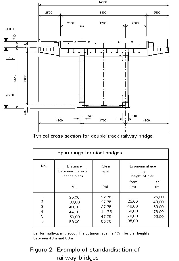
A good example of standardisation is given by the new German railway lines (N.B.S - Neubaustrecken). Taken into account the important number of bridges on the routes (about 9% of the total length), a specific planning framework was conceived; in this case, the standardisation is justified. The typical cross-section, the price of the superstructure for different spans, and the span range (no intermediate spans) are shown in Figure 2.
Fabrication of the steel forms a large portion of the overall cost of a bridge structure. Therefore, to reduce the costs of fabrication, the engineer must minimise the amount of fabricating work needed and must balance the costs of reduced material weight with the costs of increased fabrication.
The steelwork contractor and the Engineer of any steel structure must have an understanding of each other's sphere of operations in order to obtain the best solutions, both economically and technically.
Ideally, the Engineer should have a close association with the steelwork contractor and be able to discuss his ideas with him where they have a mutual bearing. Equally, the steelwork contractor should feel free to raise points with the Engineer concerning operations which will improve the end product.
Different fabricators tackle a project in different ways; in this section general principles are described, together with actual examples of specific bridges shown in Figure 3 - 8.
The structural design should provide drawings showing the following information:
a. The global geometry of the bridge.
b. Detailed geometry of elevations and sections of the bridges.
c. Size and grade of all steel sections and plates.
d. Details of all stiffeners and their connections.
e. Attachment of the concrete deck of a composite bridge to the main members.
f. Details of splices between shop fabricated members.
The design will also provide specifications for:
a. Permitted tolerances for members or the whole bridge.
b. Welding and/or bolting.
c. Requirements for non-destructive testing.
d. Surface protection.
The fabricator provides his shop with detailed fabrication drawings and the following additional information:
a. Cutting and drilling schedules for steel plates and sections.
b. Preparation of the edges of plates for welding, together with welding procedures.
The size of pieces to be fabricated is dictated by:
Pieces transported by road should normally not exceed 5 metres wide, 4 metres high, or 20 metres long, with more stringent limitations applying to rail transport. Much larger pieces can be moved by water.
Figures 3 - 6 show the sizes transported in those cases. For example, for Gisia Viaduct (Figure 3), 16 beams, 20m long on average, 19 cross frames and 2 cross girders were made separately in the fabricating shop and sent to site. Locations of the site splices were chosen to minimise the number of site butt welds and to avoid site welding of the thickest plates.
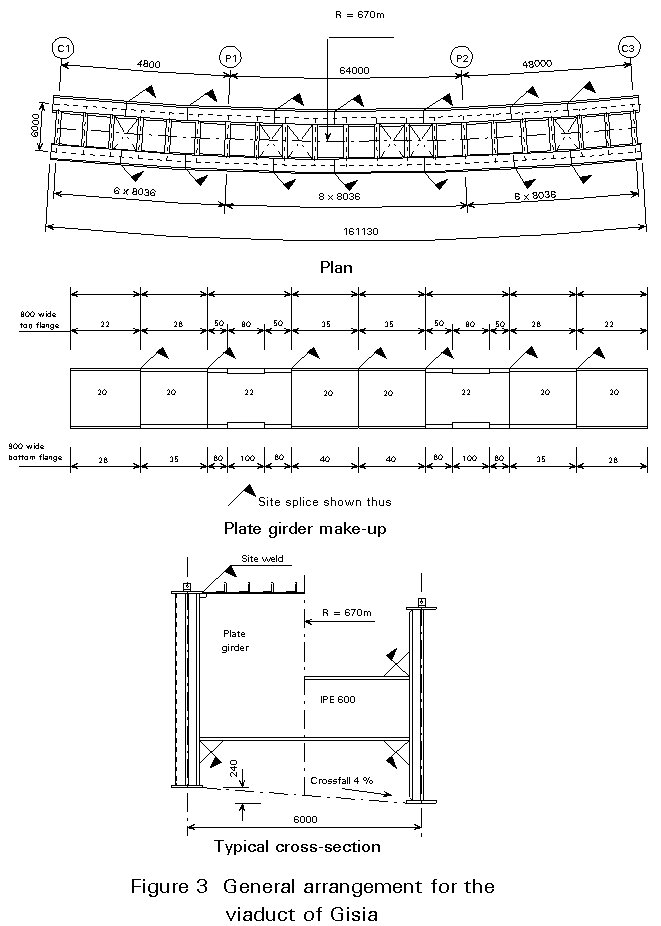
For example, the fabrication procedure for Gisia Bridge (Figure 3) was, in outline:
a. Flame cut web and flange panels.
b. Butt weld splices occurring in plates within the fabricated length, using an automatic submerged arc process. Make up lengths of flange and web plates to fabricate the required transportation length (20m) of the girder.
c. Fillet weld top and bottom flanges to webs, and attach shear connectors to top flanges.
d. Attach stiffeners and make provision for site splices.
e. Fabricate cross frames and cross girders.
Most bridges are trial erected in the fabrication shops, although improved Computer Controlled Fabrication (CCF) procedures should make this less necessary in future. Typical examples:
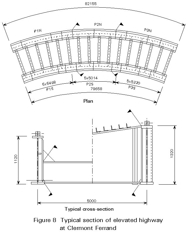
First stage: Beams P1N, P2N, P1S, P2S were erected, together with cross girders and cross frames.
Second stage: P1N and P1S were removed, the remaining part (P2N and P2S) moved along and P3N and P3S joined to it together with cross girders and cross frames.
Plate girders are very often used in the construction of steel bridges. They are usually fabricated as indicated in Figure 9.
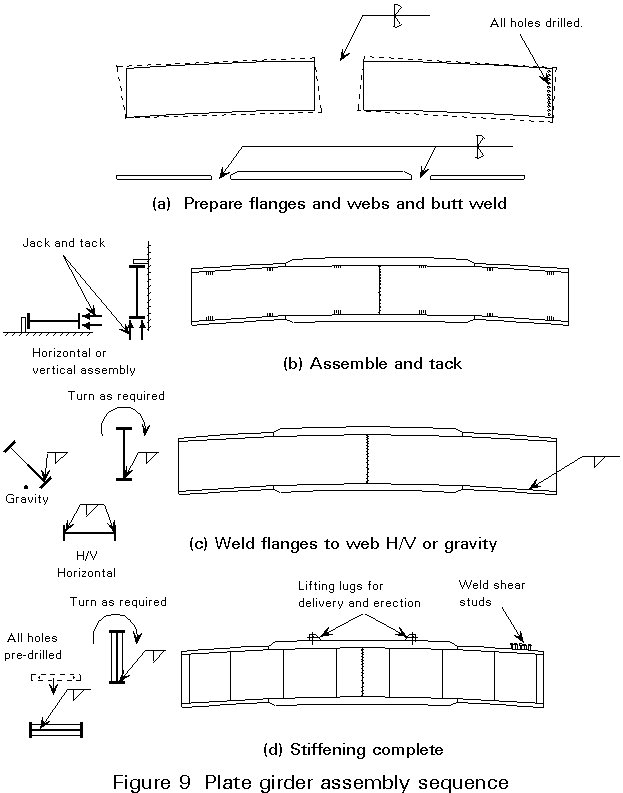
The wide variety of bridges of this type means that the sequence of fabrication has to be decided for each case depending on the facilities of the fabricator.
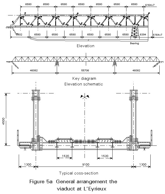
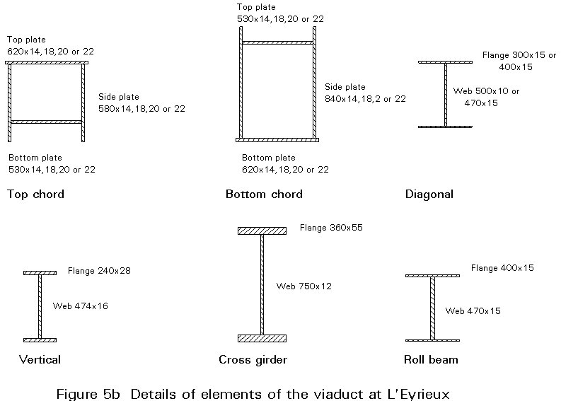
Rivetted truss elements were normally fabricated from rolled sections or plates, connected through flanges and webs, using gussets if necessary, for "piece small" erection on site. A modern version, Eyrienx Viaduct, is shown in Figure 5. High strength friction grip bolts are now used rather than rivets.
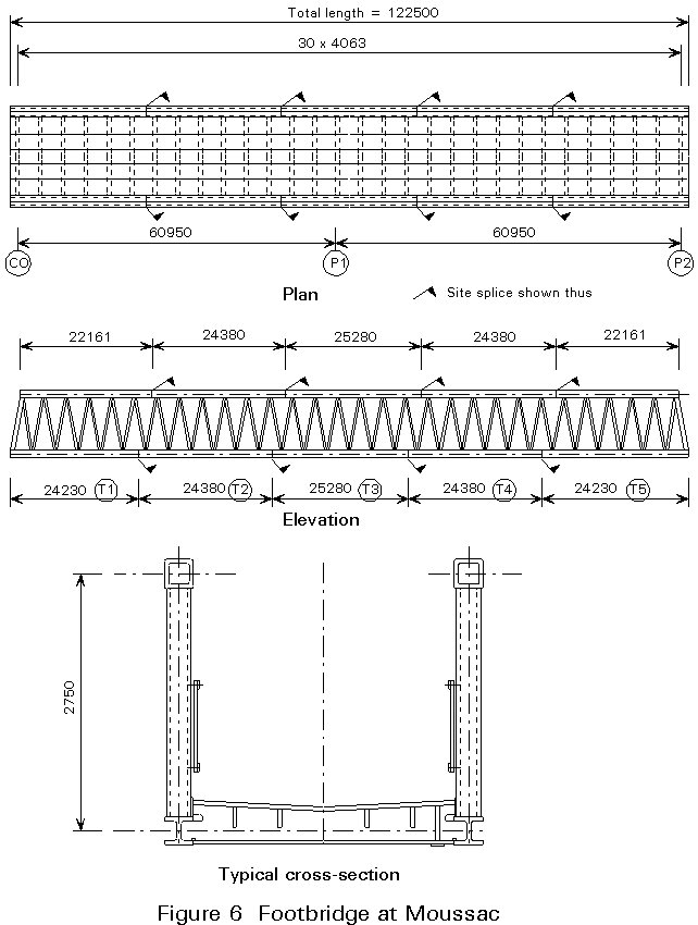
The members of many modern trussed bridges are tubular. Normally in small bridges, tubes are welded directly to each other; the complex intersection curve is well suited to CCF procedures, with complete sections being made up in the fabricating shops, e.g. Moussac Footbridge, Figure 6.
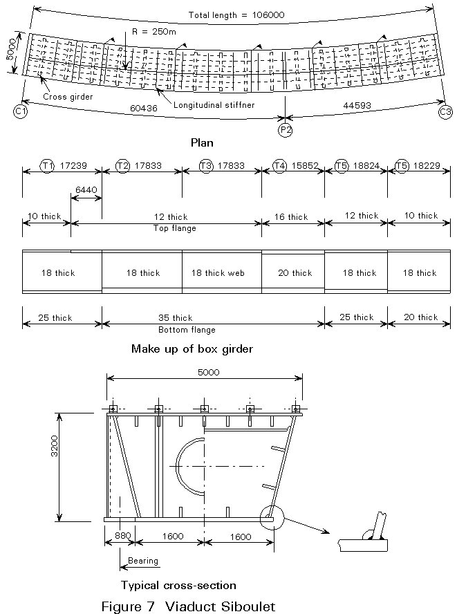
Fabrication procedures for moderate size boxes, e.g. Siboulet Viaduct, Figure 7, are similar to those used for built-up plated girders for a composite bridge.
Box girders necessitate welding of the highest quality. Long runs of automatic submerged arc welding should be used to connect webs and flanges. Unless very well executed, the connection of longitudinal stiffeners to the deck plate is very prone to premature fatigue under traffic loading.
Cross-sections of boxes at site splices must be fabricated very accurately; misalignments are difficult to correct on site. Boxes to be site spliced are frequently fabricated in pairs with the appropriate elements temporarily clamped together to guarantee alignment before shop welding the cross-section.
The steelwork contractor determines the method of transportation of sections from the shop to the site. In assessing alternatives, he will take into account economic and practical considerations such as:
If water transport is possible, much larger pieces can probably be moved. Special considerations include:
Pieces transported from the fabrication shop may be erected directly into their final positions, or they may need site assembly into larger pieces before erection. During erection, stresses in bridge elements may exceed those in service, and operatives and bridge will be subject to environmental forces (e.g. wind, temperature); an incomplete bridge is less resistant to such forces. Risks must be reduced to an acceptable level by temporary or permanent bracing, additional steelwork, or additional temporary supports to strengthen the bridge, and by barriers, safety harnesses, etc, to protect operatives. Responsibilities of everyone on site must be specified, and operatives and supervisors must know the planned sequence of erection. A failure during erection could result in the loss of a complete bridge together with operatives' lives.
Many methods of erection of steel bridges exist; five typical ones are:
Combinations of these methods are possible.
This method involves assembling the bridge from its individual components or sub-assemblies in its final position, usually on falsework or some other form of temporary support, making the site splices and removing the falsework. Adequate cranage must be provided to cover the whole of the deck area. The presence of falsework may temporarily block a road, railway or river over which a bridge is built. Assembly in situ may be used in conjunction with other methods of erection.
This method involves assembling a bridge, on rollers or skates, on its final alignment but at the side of the obstacle to be crossed. When complete it is pushed or pulled forward to cross the obstacle and land on bearings on the far side.
Whilst simple in principle, launching requires very careful control particularly of levels, supports reactions, displacements, and stresses. It requires detailed analysis since, at various stages, bridge sections may be subjected to loadings different from those in service.
Launching also requires substantial temporary works, such as a front end launching nose and a rear end counterweight and bracing, particularly against torsion. It may also require falsework on which to build the bridge on the shore, and to dismantle the nose after use. Temporary equipment may include:
This method involves lifting a self-supporting part or the whole of a bridge into or near to its final position. Pieces lifted can vary from a small footbridge weighing a few tonnes, to a large section of a major crossing weighing over 1000 tonnes. Lifting may be a complete operation in itself, or part of a cantilever erection scheme.
Lifting plant may range from small cranes for minor bridges, to very large floating cranes for major parts of estuarial bridges; alternatively winches or jacks on the already-erected part of the bridge may be used.
Connections to an already-erected part may be made whilst the section being lifted is still held by the lifter. This may be uneconomic if it prevents early release of the lifter; better would be to hold the section with a temporary clamp and release the lifter.
The contractor compares the economies of using many small cheap lifts or few large expensive lifts in deciding on the lifting operations.
This method involves constructing a bridge, normally continuous over several spans, progressively from one or both abutments, by attaching sections to the end of already-erected portion. An anchor span is lifted or assembled in situ, and sections are then cantilevered from this by either lifting them from ground level, or running them along the deck and lowering them from the end. These operations require specialist lifting and/or lowering equipment, and means for transporting large sections to the erection front. The contractor chooses between very heavy, often purpose-built, equipment or large numbers of site connections.
Cantilevering permits easy control of the bridge profile, and some control over final moment distribution in the bridge. During cantilevering, high stresses can occur. Plate girder bridges may be prone to lateral torsional instability of their compression flanges. Long cantilevers may be prone to aerodynamic excitation. Additional plate thickness or bracing, or temporary intermediate supports may be necessary.
Cantilevering is ideal for multi cable-stayed bridges, with the stays acting as intermediate supports.
This method involves building the bridge offset laterally from the final site, and then jacking it into its final position. It is typically used for replacing an existing bridge which cannot be taken out of service for a long period.
Plant required to control this operation includes runway beams, sliding plates, jacks, winches, etc, in addition to whatever is needed to build the bridge in its offset alignment.
The contractor, in choosing his method, considers such matters as:
Overriding all, of course, is the safety of the operation. The contractor compares the practicability and costs of strengthening the bridge to resist the loads imposed on it by different methods of erection.
The contractor must complete a bridge within specified tolerances, taking account of deadload deflections, erection stresses, welding distortion, shakeout of fabrication stresses, etc.
During fabrication and site assembly accuracy is dependent on correct setting out of the pieces and good connection details. Erection of a large piece can cause significant deflections in it and the rest of the bridge. The contractor must make allowance for such deflections when detailing the steelwork. During erection, he must check that the bridge is performing as predicted by making frequent surveys of critical levels, alignments, etc, allowing for effects such as temperature. Any discrepancies must be analysed before erection continues, since they may signify incorrect allowances in calculation which may be corrected by presetting of members, resetting levels or alignment of bearings, retensioning stays in cable-stayed bridges, etc.
Wind effects on a bridge may be particularly severe during erection. An incomplete bridge may have reduced transverse strength or stiffness and a long cantilever may be aerodynamically excited. Temporary bracing or guying may be necessary, or perhaps additional structural damping is required.
Operatives cannot normally work safely when windspeed exceed 20 m/s. This consideration can affect the choice of erection scheme for exposed sites.
Site connections are normally made by welding or by bolting using high strength friction grip (HSFG) bolts. Practical considerations for site connections include:
The contractor may not be known during design. When appointed he may wish to modify the site connections. The project director must be prepared to discuss such modifications.
Subject to satisfactory strength and fatigue resistance, site connections should permit site adjustment and give maximum tolerance for fabrication inaccuracies.
Any connection which, after completion, allows relative linear movement between pieces is unacceptable in a bridge. Welded joints and high strength friction grip bolted joints make completely rigid connections between sections. High strength friction grip bolts may be used in clearance holes, thus allowing some adjustment of the matching pieces before tightening. As either welding or high strength friction grip bolting are structurally satisfactory, the choice may depend on the following:
a. Preparing site splices for bolting is more expensive.
b. Welding causes distortion.
c. Incomplete bolted joints can easily be held temporarily in position with locating drifts whilst welded joints require clamps and wedges.
d. Bolting requires less skilled labour.
e. Welded joints are more prone to fatigue.
f. Bolted and intermittently fillet welded joints may suffer from corrosion problems.
g. Bolted joints normally require only visual inspection; most weld flaws are not visible, and inspection requires specialised methods.
h. Repairs to bolted joints can be carried out whilst erection proceeds. Repair of a weld must usually be done before continuing the erection.
i. Bolt heads and cover plates may foul erection equipment such as rollers.
j. Bolted joints cannot be used on steel roadway decks unless sufficiently overlain with surfacing.
k. Welding requires weather protection, particularly if low-hydrogen electrodes are being used. Bolting is less dependent on weather conditions.
l. Bolting is not suitable of joints in very thick plates. Welding such plates can be carried out with care.
To achieve expeditious, economic, technically sound and - above all - safe, construction, the organisation and chain of command on a site must be well defined. It depends on the importance and size of the project.
The Site Agent is the contractor's senior representative on site. On a large site, he may be a Director; on a small one a senior engineer or foreman. He should be permanently present on site, and be personally responsible to the contractor's management for the erection of the bridge.
On a large site the Agent's duties are largely managerial, controlling the overall programme, coordinating subcontractors if any, and delegating the detailed erection tasks to junior staff. On a small site he is personally involved in day to day operations. He makes decisions involving construction of the works and refers problems, where necessary, to the responsible person in the contractor's head office. Except in an emergency, he is not authorised to modify the erection scheme without such reference.
He keeps records of site progress, and of problems and their solution.
Depending on the size of the site, the Agent has under his control various levels of junior staff. He defines their roles (technical, administrative, supervisory, financial, etc) and determines their hierarchy.
The information provided to the Agent to enable him to manage the site includes such matters as:
The Promoter normally provides site staff, led by a Resident Engineer, to supervise and check the work of the contractor to ensure that he carries out his contractual obligations safely and expeditiously.