ESDEP WG 15B
STRUCTURAL SYSTEMS: BRIDGES
This lecture gives information about the design and detailing of truss bridges. It is intended for engineers with some experience.
Lecture 15B.2: Actions on Bridges
Lecture 15B.1: Conceptual Choice
Lecture 15B.3: Bridge Decks
The history of truss bridges is reviewed and different configurations are described. Design principles are presented, e.g. span ranges, span-to-depth ratios and arrangement of diagonals. Different sections for chords and diagonals are shown and discussed together with the connections between the members. Analysis of trusses is treated in a general way and recommendations are given on what has to be considered and what can be neglected.
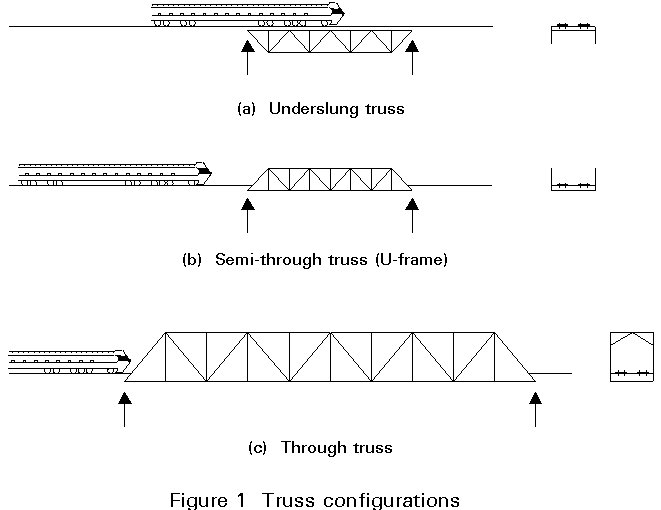
Typical configurations of truss beam bridges are shown in Figure 1. Underslung trusses are rarely used in modern construction.
Through and semi-through truss bridges are used when the depth of deck construction is very limited, for instance, when a highway or a railway crosses a canal.
It is unusual for through-trusses to be economic for highway bridges, except for very long spans. With less severe restrictions on the gradients on the approach embankments it is, in addition, much easier for a road to gain the height required for a deck bridge than for a railway to do so.
Semi-through trusses tend therefore to be used for highways while through and semi-through trusses are still used for railways.
The principle of a truss is simple. The structure is composed of top and bottom chords triangulated with diagonals and/or verticals in the webs so that each member carries purely axial load. Additional effects do exist but in a well designed truss they will be of a secondary nature and may be neglected.
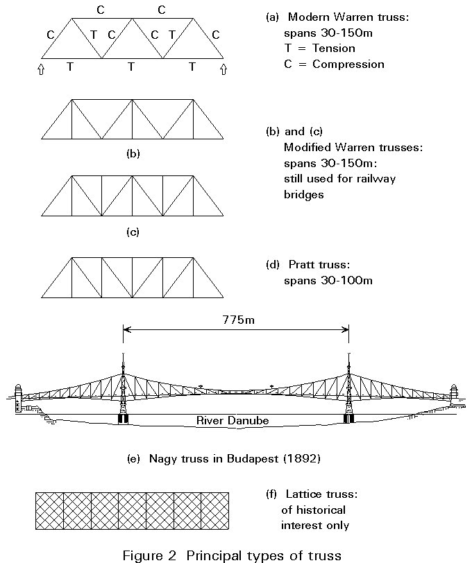
Global moment on a truss is carried as compression and tension in the chords as shown in Figure 2a. Global shear is carried as tension or compression in the diagonal and vertical members. In the simplified case, where the joints are considered as pinned, and the loads are applied at the nodes, the loading creates no bending moment, shear, or torsion in any member. Loads applied in such a way as to cause bending, shear, or torsion usually result in inefficient use of material.
The saving of material compared to a plate girder is clear when the webs are considered. In a truss the webs are mainly 'fresh air' - hence less weight and less wind pressure.
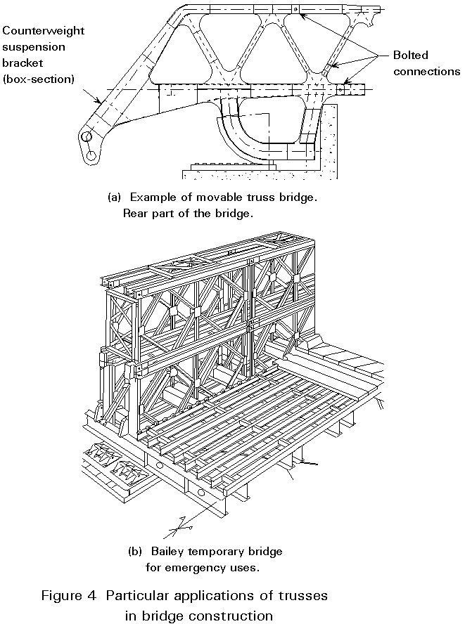
A truss can be assembled from small easily handled and transported pieces, and the site connections can all be bolted. Trusses can have a particular advantage in countries where access to the site is difficult or supply of skilled labour is limited. Undamaged parts of a truss bridge can easily be re-used after an accident or the effects of war.
The truss as a structural form dates back to Roman times. A bronze truss was used in the Pantheon.
In the nineteenth century, the United States can claim to have created the greatest number of different types of truss. Their use of timber and their enthusiastic pioneering spirit created some unlikely looking structures, but nevertheless firmly established the truss as the ideal form of bridge at that time for medium spans.
Eiffel built lattice trusses in France (Figure 2f). Fowler and Baker, however, introduced a major innovation by adopting steel tubular sections as the main compression members for the Forth Bridge which is well known throughout the world for its grandeur. Modern truss bridges also use box sections for the compression members.
The Hungarian architect Virgil Nagy built the very aesthetic Ferenc Jozsef truss girder bridge in Budapest over the Danube in 1892. The bridge is supported by Pratt-truss girders of variable height (Figure 2e). The central span is 175m long with an isostatic central part of 47m.
For most modern bridgework the Warren truss (with its modifications) is perhaps the most commonly used type because of its simplicity. Modern labour costs dictate a minimum of members and connections.
The Warren configuration shown in Figure 2 is usually chosen. When the length of the gap to be crossed makes the use of a multiple span bridge unavoidable, it is cheaper and usually possible to raise the road line and build another type of bridge requiring a greater depth under the deck.
For this reason highway truss bridges usually have only one span (Figure 3). Their appearance is well adapted aesthetically to cross canals in flat landscapes.

The spans are usually between 60 and 120m which is the normal economic range. The longest span was the old Neuwied bridge over the Rhine (212m) which was replaced by a cable stayed bridge.
The span-to-depth ratio is normally about 15.
Three basic truss bridge configurations are shown in Figure 1.
The most economic truss bridge configuration, especially for railway bridges, is the underslung truss where the live load runs at the level of the top chord. The top chord then serves the dual function of support for the live load (as the sleepers sit directly on the chord) and the main compression member. There is, however, the disadvantage that clearance under the bridge is reduced. It is thus common for the approach spans over a flood plain, or over unnavigable parts of the river, to be underslung while the navigation channels are crossed with through trusses.
Where the spans are short, and underslung trusses are not possible, it may be economic to have the top chord below the loading gauge level by using semi-through trusses. Bracing between the top chords is not possible and restraint to the compression members has to be provided by U-frames. However for spans where semi-through trusses have been used in the past, plate girder bridges are now very competitive, and now semi-through trusses are seldom used for railway bridges.
Where the spans of railway bridges are long the economic depth is usually great enough to allow bracing to be provided above the loading gauge level. Such trusses are termed 'through trusses'. The use of material in bracing rather than U-frames is considerably more efficient.
For shorter spans the choice is between the Warren and the Pratt configuration. In the simple Warren truss, the diagonals work alternatively in compression and tension, whereas in the Pratt truss, all the diagonals are in tension and the shorter posts take compression.
To cater for the heavy loading on railway bridges, the cross girders should be fairly close together. This requirement leads to the hangers of the Modified Warren truss which sub-divide the bottom chord. Economic design of the top compression chord leads to sub-division with a post.
The majority of truss bridges are simple spans, but there are many examples of continuous trusses. The immediate benefit on member forces when a continuous structure is employed is offset to some extent by increased fatigue effects. In a simple truss it is common for only some of the diagonals to be influenced by fatigue. These diagonals are usually those at mid-span where the smallest available section has to be used in any case. In contrast, most of the diagonals in a continuous truss, and some of the chord members may well have to be checked for fatigue, particularly when welded construction is used.
Even where continuous trusses show savings in the use of steel, they may not be economic. On a 1700m long bridge in India, the alternative continuous truss design was about 5% lighter that the simple spans which were considered more economic on account of standardization of fabrication detail and erection procedure.
It should be noted here that the design loading has a considerable effect on the truss configuration. For example, with combined highway and rail loading, trusses with two decks can be very economic.
For spans from 60m to 120m for highways and from 30m to 150m for railways, simple spans can prove economic when favourable conditions exist.
Large spans using cantilever trusses have reached a main span of 550m. Trusses have to compete against plate girders for shorter spans, against box girders for medium spans and cable-stayed bridges for longer spans.
The optimum value for this ratio depends on the magnitude of the live load that has to be carried. It should be in the region of 10, being greater for road traffic than for rail traffic. For twin track rail loading the ratio may fall to about 7,5. A check should always be made on the economic depth for a given bridge.
For short and medium spans, it will generally be found economic to use parallel chords to keep fabrication and erection costs down. However, for long continuous spans, a greater depth is often required at the piers, Figure 2e.
Skew truss bridges should be avoided as far as possible.
An even number of bays should be chosen to suit the configuration of diagonals in Pratt and modified Warren trusses. If an odd number is chosen there will be a central bay with crossed diagonals. This arrangement is not usually desirable except perhaps at the centre of a swing bridge. The diagonals should be at an angle between 50° and 60° to the horizontal.
Secondary stresses should be avoided as far as possible by ensuring that the neutral axes of all intersecting members meet at a single point, in both vertical and horizontal planes. This will not always be possible, e.g. cross girders will be deeper than the bottom chord and bracing members may be attached to only one flange of the chords.
Grade S355 steel should be used for the main members with Grade S275 or S235 used only for members carrying insignificant load, unless the truss has to be fabricated in a country where there is no ready supply of higher grade steel. For a truss designed using Grade S355 steel, the amount of Grade S275 or S235 steel used would normally be about 7%. For very long spans higher grades will be economical, e.g. quenched and tempered steel or thermo-mechanically processed steel with yield strength 500 - 600 MPa, provided that fatigue is not governing.
These members should be kept as short as possible and consideration given to additional bracing if economical.
The effective length for buckling in the plane of the truss is normally not the same as that for buckling out of the plane of the truss. This effect can be further complicated in through trusses where horizontal bracing may be provided at mid panel points as well as at the main nodes. When making up the section for the compression chord, the ideal disposition of material will be one that produces a section with radii of gyration such that the ratio of effective length to radius of gyration is the same in both planes. In other words, the member is just as likely to buckle horizontally as vertically.
Eurocode 3: Part 1.1 [1] permits the effective length factors for truss members to be determined by analysis. Otherwise very conservative values are given of 1,0 and 0,9. However, as Eurocode 3: Part 1 applies to buildings, which have relatively small span trusses where absolute economy in steel weight is not vital, it is assumed that the clause is not appropriate to bridges. It is anticipated that the effective length of bridge truss members will be covered in Part 2 of Eurocode 3 [2]. As an example of current practice see Table II of BS5400 Part 3 [3].
In the case of semi-through bridges, the top chord is supported laterally by the diagonals and behaves as a strut supported on springs. The method of determination of its effective length is given in the appropriate bridge codes.
The depth of the member needs to be chosen so that plate dimensions are sensible. If they are too thick, the radius of gyration will be smaller than it would be if the same area of steel was used to form a larger member using thinner plates. The plates should be as thin as possible without losing too much area when the effective section is derived.
Trusses with spans up to about 100m often have open section chords, usually of "top-hat" section, see Figure 5. Here it is often desirable to arrange for the vertical posts and struts to enter inside the top chord member, thereby providing a natural diaphragm and also, usually, avoiding the need for gussets at alternate nodes, although packs will be needed.
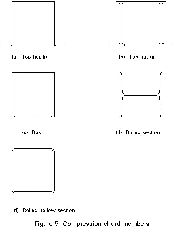
For trusses with spans greater than about 100m, the chords will usually be box shaped so allowing the ideal disposition of material to be made from both economic and maintenance viewpoints.
For shorter spans rolled sections or rolled hollow sections may occasionally be used.
Advantages and disadvantages and comments on fabrication of the five alternative configurations shown in Figure 5 are:
a. Top Hat (i)
b. Top Hat (ii)
c. Box
d. Rolled Sections
e. Rolled Hollow Sections
Tension members should be as compact as possible, but depths have to be large enough to provide adequate space for bolts at the gusset positions. The width out of the plane of the truss should be the same as that of the verticals and diagonals so that simple lapping gussets can be provided without the need for packing.
It should be possible to achieve a net section about 85% of the gross section by careful arrangement of the bolts in the splices. This means that fracture at the net section will not govern for common steel grades.
As with compression members, box sections would be preferable for ease of maintenance but open sections may well prove cheaper.
Four alternative configurations are shown in Figure 6.
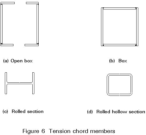
Their advantages and disadvantages are:
a. Open Box
b. Box
c. Rolled Section
d. Rolled Hollow Section
These members should be all the same width normal to the plane of the truss to permit them to fit flush with or to be slotted inside the top chord (where the top-hat section is used) and to fit flush with the bottom chord. However, the width of the diagonals in the plane of the truss should be reduced away from the supports by about 75mm per panel. This reduction may mean that some members are understressed. It is often possible to use rolled sections, particularly for the lightly loaded members, but packs will probably be required to take up the rolling margins. This fact can make welded members more economic, particularly on the longer trusses where the packing operation might add a significant amount to the erection cost.
Aesthetically, it is desirable to keep all diagonals at the same angle, even if the chords are not parallel. This arrangement prevents the truss looking over-complex when viewed from an angle. In practice, however, this is usually overruled by the economies of the deck structure where a constant panel length is to be preferred.
Five alternative configurations are shown in Figure 7.
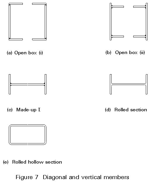
Their advantages and disadvantages are:
a. Open Box (i)
b. Open Box (ii)
c. Made-up I
d. Rolled Sections
e. Rolled Hollow Sections
As with any structural design, the problems that may confront the maintenance team should be fully appreciated. The problems can be numerous, but a good design will avoid most of the common difficulties. For example:
Water
Dirt and Debris
Painting
Birds
Unless an orthotropic or concrete deck is provided, stringer bracing, braking girders and chord lateral bracing are needed to transmit the longitudinal live loads and the wind and/or earthquake loads to the bearings and also to prevent the compression chords from buckling. When a solid deck is used, the interaction between deck and trusses has to be considered.
For the lateral bracing of the chords, where a "Saint Andrew's Cross" type system as shown in Figure 8a is adopted, the nodes of the lateral system will coincide with the nodes of the main trusses. Interaction will take place which must be taken into account. As a result of the interaction, the lateral system may carry as much as 6% of the total axial load in the chords.
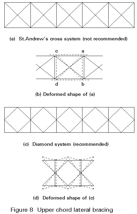
Figure 8b shows the lateral system in its original form and in its distorted form after axial compressive loads are applied in the chords. Owing to the shortening of the chord members ac and bd, the rectangular panel deforms as indicated by the dotted lines, causing compressive stresses in the diagonals and tensile stresses in the transverse members. The transverse bracing members are indispensable for the correct performance of a St Andrew's cross bracing system.
The interaction can be significantly reduced by using a "Diamond" system of lateral bracing where the nodes of the lateral system occur midway between the nodes of the main trusses, Figure 8c. With this arrangement, "scissors-action" occurs when the chords are stressed, and the chords deflect slightly laterally at the nodes of the lateral system.
In the principal buckling mode of a "Diamond" lateral bracing system, one half of the diamonds have all their members in tension (see Figure 9). For the top laterals a diamond system with kickers at the panel points halves the transverse effective length of the compression chord as shown in Figure 10.
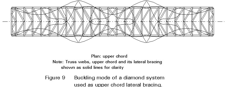
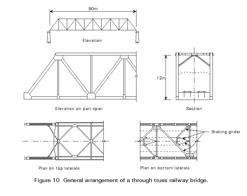
For railway bridges, Figure 9 illustrates an economic lateral system at deck level which consists of a simple single member which also functions as part of the braking girder. The additional girders help to resist the braking forces arising from trains. In addition the lateral is supported by the stringers so the effective length is only about a third of the panel length.
Wind loading on diagonals and verticals can be split equally between top and bottom lateral systems. The end portals (either diagonals or verticals) then have to carry the load applied to the top chord down to the bottom chord.
Clearly, where only one lateral system exists (as in semi-through or underslung trusses), then this single system must carry all the wind load.
In addition to resisting externally applied transverse loads due to wind, etc. lateral bracing stabilizes the compression chord. The lateral bracing ensures that reasonably small effective lengths are obtained for the truss members. Local lateral bracing is also required at all 'kinks' in the chords where compressive loads are induced into the web members irrespective of whether the chord is in tension or compression because of the angular direction change of the chord.
Generally trusses have stiff joints. The secondary stresses due to joint stiffness and truss deformation can be ignored in the ultimate limit state check. They have to be considered where the serviceability limit state check is required, and for fatigue. However, these secondary effects are generally insignificant.
The serviceability check is not required for tension members or for some slender compression members. Where it is not required, the traditional manual method of truss analysis assuming pin joints is adequate for global analysis.
Computer analysis can take joint stiffness into account and secondary moments are determined automatically. The effects of the primary axial loads and the secondary moments are combined by the use of suitable interaction formulae.
In a statically indeterminate truss, temperature effects have to be considered. They are usually not significant.
i. Loads not applied at truss joints
Two types of local load effects have to be considered:
a. Those due to loads applied in the plane of the truss away from a joint. A typical example of this type of loading is on the upper chord of an underslung railway bridge where the sleepers rest directly on the top flange of the chord.
b. Eccentric loads not in the plane of the truss, such as loads from cross girders.
ii. Eccentricities at joints
Flexural stresses due to any eccentricity at joints have to be taken into account by sharing the moments due to eccentricity between the members meeting at joints in proportion to their rotational stiffness. For the main trusses the centroidal axes of all members should meet at a point wherever possible. The only case where a small degree of eccentricity is unavoidable is when asymmetrical "top-hat" sections are used and it is not possible for the centroidal axes of adjacent members of different sizes to be co-linear.
Where possible the axes of the lateral systems should be in the same planes as those of the truss chords. However sometimes the upper laterals of a through truss have to be connected to the top flange of the upper chord and eccentricity is unavoidable. Since the loads in upper lateral systems are generally small, the additional resulting stresses are insignificant. Similarly on some through bridges, the bottom laterals have to be connected to the bottom flange of the lower chord to avoid the cross girders and stringers.
The major connections in bridge trusses occur at the truss nodes where the web members are connected to the chord members. This connection usually incorporates a splice in the chord member and sometimes also in one or both of the minor truss connections joining the cross girder and the lateral system to the truss.
Site connections can be made by high strength friction grip bolts for reasons of economy and speed of erection. Good site welds are difficult to achieve where access is difficult and fatigue life of welded joints is lower than that of bolted joints.
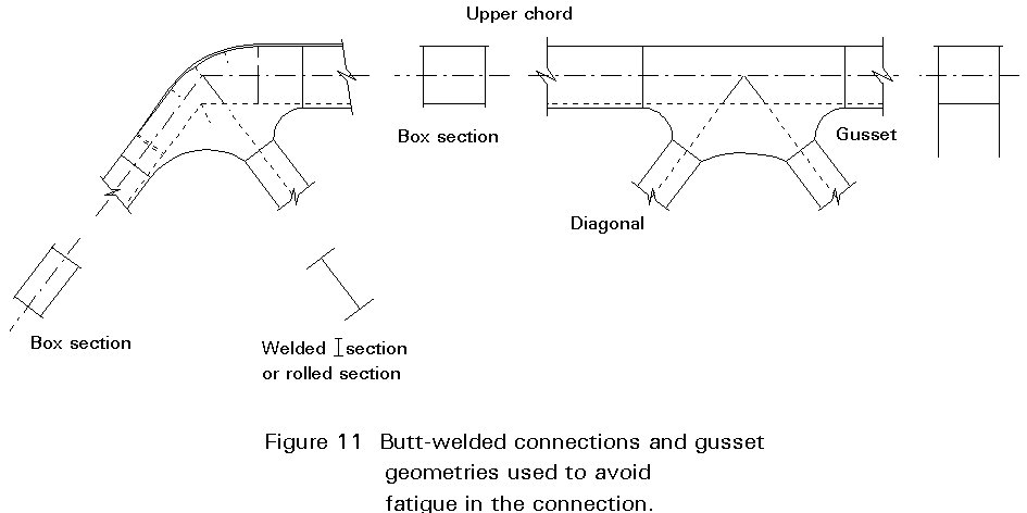
However, in several countries, the connections are now usually butt-welded on site. Figure 11 shows different gusset geometries which are used to obtain durability in view of the fatigue-governing effects.
When a concrete slab is cast in place to support the highway or the railway, the horizontal forces caused by the shrinkage of the concrete should be taken into account in the design of the lower chord connection joints.
At the nodes of a truss where the web members are connected to the chords, there is a change in load in the chord which necessitates a change in its cross-section area. The node is, therefore, the point at which there is a joint in the chord as well as being the connection point of the web members.
The web members are connected to the chords by vertical gusset plates. They are usually bolted to the chord webs and the web members fit between them (Figure 12a).
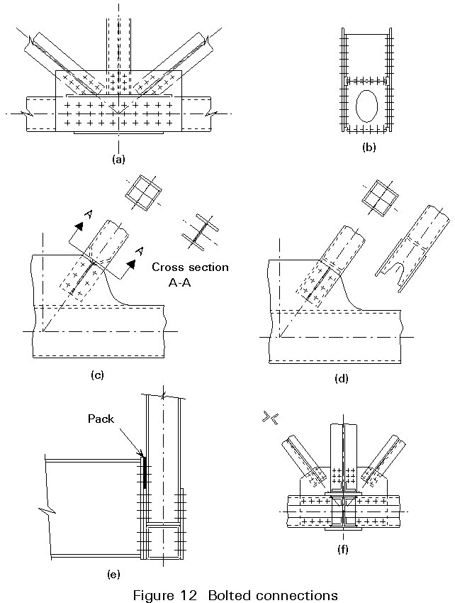
The chord joint is effected by providing cover plates. They should be so disposed, with respect to the cross-section of the member, as to transfer the load in proportion to the respective parts of the section (Figure 12b). The gusset plates form the external web cover plates. Since they work in the dual capacity of cover plate and web connector, their thickness takes this into account. The joint is designed to carry the coexistent load in the lesser loaded chord plus the horizontal component of the load in the adjacent diagonal. The load from the other diagonal is transferred to the more heavily loaded chord through the gussets alone. In compression chords which have fitting abutting ends in contact, design codes allow up to 75% of the compressive load to be carried through the abutting ends.
Sometimes the gusset is formed by shop-welding a thicker shaped plate to the chord in place of the chord web. The web members are then all narrower than the chords and the chord splice is offset from the node. An advantage occurs in erection as the web connections can be made before the next chord is erected.
At the connections of all tension members and elements, care has to be taken in the arrangement of bolt holes to ensure that the critical net section area of the section is not so small that fracture will govern. If necessary staggering the lines of bolts helps to increase the effective nett area. Remember that the critical net section is usually at the ends of the section or the centre of the cover plates, and that elsewhere some of the load has been transferred to the other parts of the joint and more bolt holes can be tolerated.
Connections of web members to gussets are quite straightforward and special treatment such as the use of lug angles is rarely required. In connecting rectangular hollow sections the method shown in Figure 12d is preferable to that of Figure 12c.
Unsupported edges of gussets should be such that the distance between connections does not exceed about 50 times the gusset plate thickness (Figure 12a). If this is unavoidable, the edge should be stiffened.
They are quite straightforward. The 2 or 4 rows of bolts in the cross girder end plate are made to correspond with the equivalent central rows of bolts in the gusset. Packing plates may be required to accommodate the difference in height of gussets and cross girders (Figure 12e).
As recommended in 5.2(ii) the axes of the lateral systems should be in the same planes as those of the truss chords. This requirement is met in 2 of the 3 types of lateral members and connections described below:
i. For long and medium spans, the lateral members are frequently made from two rolled channel sections connected by lacing to give an overall depth the same as the chords. They are connected to the chords by gussets bolted to the chord flanges exactly as the main web members are connected to the main joint gussets.
ii. For medium spans, laterals consisting of two rolled angles arranged toe to toe in "star" formation and with intermediate battens are often ideal. They are connected to the chords by gussets positioned at the chord axis (Figure 12f). Note, angles "back-to-back", but separated by a small gap should never be used because of maintenance problems.
iii. On short spans single laterals often suffice. They can be connected by a gusset to the upper or lower chord flange, as the moments due to eccentricity are small.
[1] Eurocode 3: "Design of Steel Structures": ENV 1993-1-1: Part 1.1. General Principles and Rules for Buildings, CEN, 1992.
[2] Eurocode 3: "Design of Steel Structures": Part 2: Bridges and Plated Structures (in preparation).
[3] BS5400: "Steel, Concrete and Composite Bridges", Part 3: 1982: Code of Practice for Design of Steel Bridges, British Standards Institute, London.