ESDEP WG 15B
STRUCTURAL SYSTEMS: BRIDGES
To introduce the types of bridge deck used for highway and railway bridges and their methods of design and construction.
Lecture 15B.1: Conceptual Choice
Lecture 15B.4: Plate Girder and Beam Bridges
Lecture 15B.5: Truss Bridges
Lecture 15B.6: Box Girder Bridges
Lecture 15B.7: Arch Bridges
Lecture 15B.8: Cable Stayed Bridge
Lecture 15B.9: Suspension Bridges
Lecture 15B.10: Bridge Equipment
Bridge traffic is carried directly on the bridge deck. In highway bridges, the concrete slab is a very common deck type, and its usefulness is further increased when composite methods of construction are used. Recent bridges which have adopted the integral steel deck-and-flange system have stiffened the deck by longitudinal stiffeners comprised of either simple vertical members or torsionally strong U sections. The longitudinal stiffeners function partly as stringers and partly as plate stiffeners. In railway bridges, the rail track is either carried on cross ties which may be directly on the girders or on sleepers which rest on ballast. The ballast helps to reduce noise and vibration and allows continuous track maintenance.
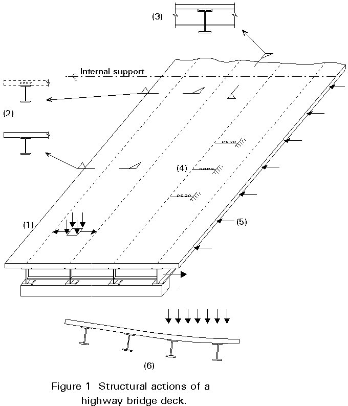
The principal function of a bridge deck is to provide support to local vertical loads (from highway traffic, railway or pedestrians) and transmit these loads to the primary superstructure of the bridge, Figure 1(1). As a result of its function, the deck will be continuous along the bridge span and (apart from some railway bridges) continuous across the span. As a result of this continuity, it will act as a plate (isotropic or orthotropic depending on construction) to support local patch loads.
Continuity ensures that whether or not it has been designed to do so, it will participate in the overall structural action of the superstructure.
The overall structural actions may include:
It may be necessary to take account of these combined actions when verifying the design of the deck. This is most likely to be the case when there are significant stresses from the overall structural actions in the same direction as the maximum bending moments from local deck actions, e.g. in structures with cross girders where the direction of maximum moment is along the bridge.
The passage of each wheel load causes a complete cycle of local bending stresses. The number of significant stress cycles is, therefore, very much higher for the deck than for the remainder of the superstructure. In addition, some of the actions of the deck arising from its participation in the overall behaviour are subject to full reversal; an example is the transverse distribution of vertical load between girders. For both these reasons, fatigue is more likely to govern the design of the bridge deck than the remainder of the superstructure.
Modern decks consist of concrete slabs or orthotropic steel decks. Despite the different materials, it is possible to identify common themes in their development.
Partly because of limited understanding of behaviour and methods of analysis, and partly because it suited historical methods of construction, early decks were separated from the remainder of the superstructure. The steel "battledeck" shown in Figure 2(a) comprised plate panels welded to rolled beams as stiffeners that were supported by and spanned simply between cross-girders which, in turn, spanned between the principal girders. The deck construction was relatively deep but could still fit within the overall depth of the truss. A similar approach can be seen in the concrete deck slab in Figure 2(b). The slab acts compositely with the stringers but does not contribute to overall bending.
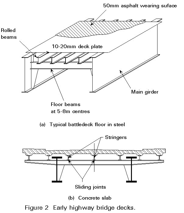
Although this separation reduced the overall efficiency of the design, it is noteworthy that it does assist bridge repairs. For example, the entire deck of the Golden Gate Bridge in San Francisco was replaced during night time possessions, permitting the bridge to continue to be used during the day.
Modern decks in both materials are fully integrated into the overall superstructure as shown in Figure 3. These integrated decks improve the economy of the primary structure considerably. In all - steel construction the cross girders and main girders do not need separate top flanges. With a concrete deck, rolled sections (used for cross girders and main girders for short spans) will be considerably lighter. The top flanges of plate girders will typically be half the cross-section that would have been needed for non-composite construction.
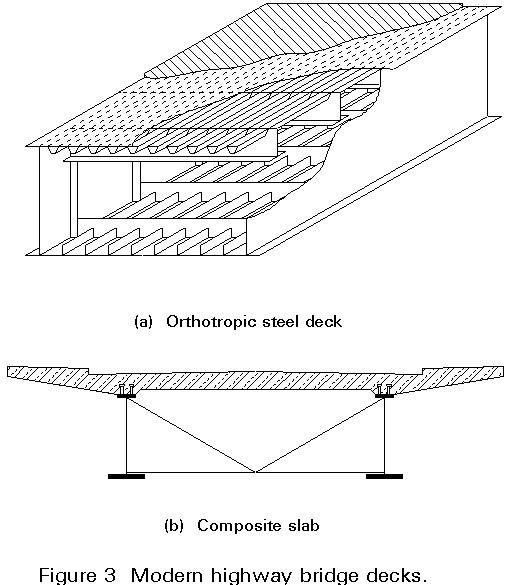
The disadvantage of integrated construction is that repair or replacement of the deck is difficult and usually requires prolonged closure of the bridge.
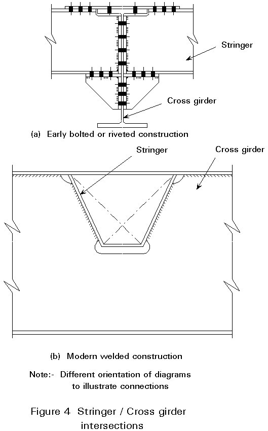
The increasing ratio of labour to material costs has encouraged the development of simpler forms of construction. Simplification has been considerably assisted by the development of modern welding techniques.
For example, early attempts to arrange stringers and cross-girders at the same level required the bolted or riveted connection shown in Figure 4a. Its modern equivalent in Figure 4b is readily accomplished with reliable welding.
A very important aspect of the historical development of steel decks is the evolution in form of longitudinal stiffeners or stringers. Initially, only open stiffeners shown in Figure 5a were utilised. Flats (i) and (ii) are simple to work with but are relatively inefficient in bending; bulb flats (iii) are more efficient in bending but are prone to lateral instability; tees (iv) and angles (v) offer a good combination of longitudinal bending strength and resistance to lateral buckling. All these open stiffeners have the basic disadvantage that they are flexible in torsion. Their use leads to a panel that is strongly orthotropic with little torsion stiffness (Dx >> Dy or Dxy). Such panels are inefficient as transverse distribution of local loads leading to a narrow effective width in bending and high longitudinal stresses under patch loading.
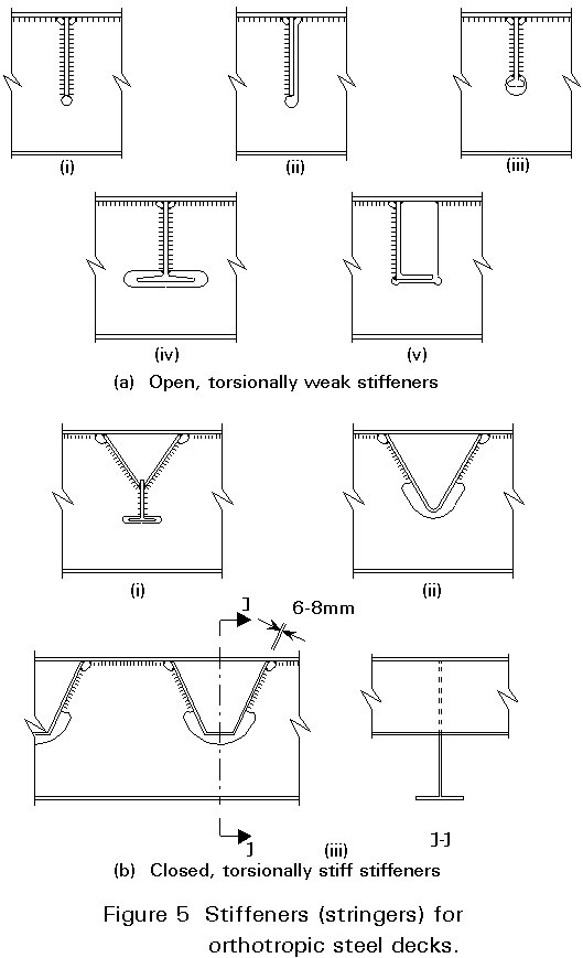
It would be possible but expensive to introduce local transverse stiffeners to increase Dy, but it is feasible to increase Dxy, and thereby improve transverse distribution, by using closed stiffeners. Figure 5b shows the closed stiffeners that have been developed. Initially, the "wineglass" stiffener (i) was developed for the early post war Rhine bridges in Germany. This stiffener gave a good combination of torsional and bending stiffness but was expensive to fabricate. Subsequently, the Vee and the trapezoidal stiffener were developed. The latter gives better bending resistance than the former, although it loses some torsional stiffness from cross-section distortion.
The earliest welded battledecks were detailed with continuity to the web of the cross girder, for example (a)(i). This created a very poor fatigue detail for the stringers. Subsequently, it became common practice to slot the web and have continuous stringers, for example (a) (iv) + (v) and (b) (ii) and (iii). With suitably rounded openings in the web, no fatigue problem is created in that element. It is noteworthy that the extreme fibres of the stringers are also not welded, thereby improving their fatigue performance.
Reinforced concrete slabs are used for a wide range of composite bridges. Where they are supported at close centres, i.e. up to 3,5m, as shown in Figure 6a, they will usually have a uniform depth of 220 to 250 mm.
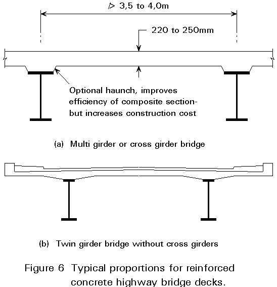
Concrete slabs are also used for widely spaced girders, as shown in Figure 6b. In such cases, the economies that can be achieved by reducing dead weight justify the extra cost of using variable depth slabs, as shown.
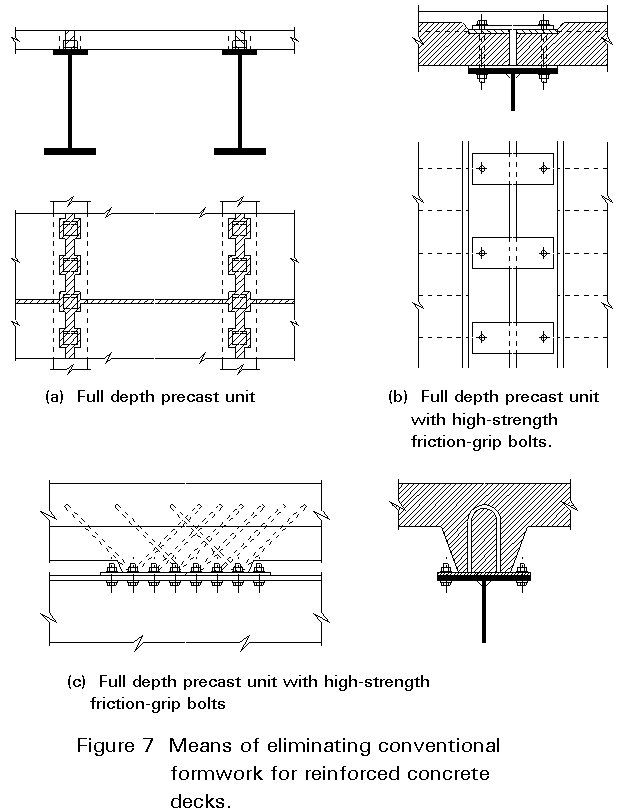
It is possible, and is still quite common, to cast the concrete slab in situ on conventional formwork. However, considerable ingenuity has been devoted to improving this form of construction. Examples include:
Apart from certain types of slab with participating pre-cast planks, all reinforced concrete slabs are isotropic and may be analysed by simple plate methods. Analysis needs to consider the various modes of behaviour of the slab.
The effective breadth of the slab is included in the modulus of the girders. The stress resultants, compression at midspan, tension at supports, can readily be determined from the global analysis. The midspan regions are likely to be satisfactory in compression; the support regions usually require additional reinforcement, which should be placed within the effective breadth of the slab.
The treatment is similar to that for the longitudinal girders.
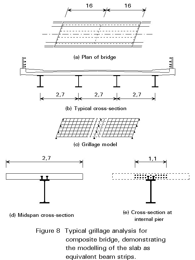
This effect should also be modelled within the global analysis. Usually the slab is replaced by equivalent beams in the grillage analysis, as shown in Figure 8. Not less than eight beam strips are recommended for each span to ensure adequate modelling of the structure. Calculation of the bending stiffness of the beam strip is straightforward - the slab is assumed to be uncracked and fully effective. It is also necessary to model the torsional stiffness of the slab - this is best done by distributing the total torsional rigidity equally between the transverse beam strips and the longitudinal twin girders, i.e. assign
per unit width to both directions, where d is the depth of the slab.
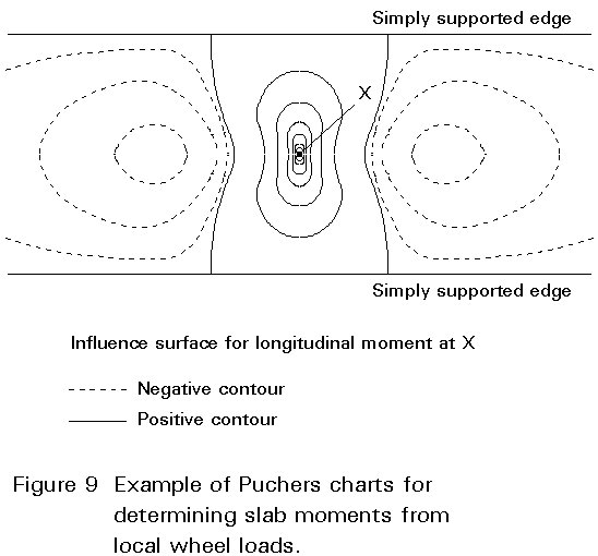
Analysis is required only of the slab local to the wheel load. Most practical situations can be reduced to standard cases and evaluated using standard influence charts [1]. Figure 9 shears schematically a typical chart (Pucher Influence chart). The patch leads are applied to the chart in a way that maximises the volume under the influence surface. The volume is then evaluated numerically. The simplification of support conditions to permit use of standard charts normally leads to a conservative assessment of worst moments.
Once the methods of analysis have determined the overall combination of moments, axial forces and shears on the slab, its adequacy in compression and shear can be checked and the reinforcement detailed in the conventional way. It is customary for some compression reinforcement to be required in the regions of highest moment.
Orthotropic steel decks have been subjected to considerable practical optimisation. The principal motivation for optimisation has been to develop the cheapest deck that will achieve a satisfactory fatigue life. There have been substantial problems with fatigue cracking, both at the stiffener/deck welds and the stiffener/crossgirder connections. The former has led to the use of thicker deck plate and more fatigue resistant welds; the latter has led to a particular form of welded connection.
The outcome of this practical optimisation has been the development of the standard "European" orthotropic deck that is described below.
Although the functions and the resulting stresses of the component parts of a steel-deck bridge are closely interrelated, it is necessary for design purposes to treat separately the three basic structural systems, as follows [2]:
System I. The main bridge system, with the steel deck acting as a part of the main carrying members of the bridge.
In the computation of stresses in this system in girder-type bridges the entire cross-section area of the deck, including longitudinal ribs, may be considered effective as flange.
System II. The stiffened steel-plate deck, acting as the bridge floor between the main members, consists of the ribs, the floor beams, and the deck plate as the common upper flange.
The major contribution of Pelikan and Esslinger [3] is in the prediction of the behaviour of System II, the continuous orthotropic plate on flexible supports.
System III. The deck plate, acting in local flexure between the ribs, transmitting the wheel loads to the ribs. The local stresses in the deck plate act mainly in the direction perpendicular to the supporting ribs and floor beams and do not add directly to their other stresses.
The governing stresses in the design of the deck are obtained by superposition of the effects of Systems I and II.
Figure 10a shows the basic cross-section of this deck which is judged to provide the most cost-effective and fatigue resistant design.
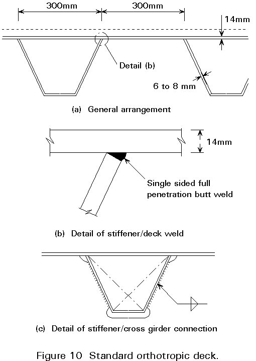
The most important detail of construction is the deck/stiffener weld. For a reliable fatigue life a sound full penetration weld is essential, Figure 10b. This can be achieved by a square cut to the end of the stiffener, providing that qualified weld procedures are adopted and a consistently good fit is achieved between the two plates. The latter requires careful manufacture of the trough stiffener and adequate jigs and clamps on the panel welding line.
Another important detail is the stiffener to cross girder (or diaphragm) connection shown in Figure 10c. The stiffener is continuous through an opening in the cross girder to ensure full continuity. Only the webs of the stiffener are welded to the cross girder; this improves the fatigue performance of the stiffener. The upper and lower `mouse holes' have corner radii to minimise stress concentrations in the cross girder.
The detailed analysis of the orthotropic deck is well documented [2, 4]. The most practical method of analysis is that of Pelikan and Esslinger. This method is based on the application of Huber's equation. It assumes that the deck system is a continuous orthotropic plate, rigidly supported by its main girders and elastically supported by the floor beams.
The design procedure is divided into two stages:
Points of particular note are :
In principle, the design of the deck should be verified separately for static strength and fatigue resistance. For static strength the individual components of the deck need to be checked for the following stresses, in combination:
For fatigue loading the critical regions are those identified in 3.2.3 above. In practice, adequacy is demonstrated by experience rather than by calculation of the very complex elastic stress fields.
Usually, the flanges of bridge cross-sections are relatively wide with respect to their spans. The effects of shear lag need, therefore, to be included in the bending analysis.
Shear lag effects cause the stress distribution over the cross-section to be non-linear. The maximum stress values occur at the flange-to-web junctions. The effective width is defined by the condition that the stresses at the flange-to-web junction, according to engineering bending theory, must be identical to the maximum stresses calculated by applying the mathematical theory of elasticity.
The effective width bm is defined as the width of a rectangular area of height (dx)max, and having the same area as that enclosed by the distributed curve stress area. The effective width, Figure 11a is calculated by the following equation.
bm = 
To solve this equation, it was necessary to establish simultaneous differential equations for determining both the deflection of the girder and the axial displacements at any point of the plate.
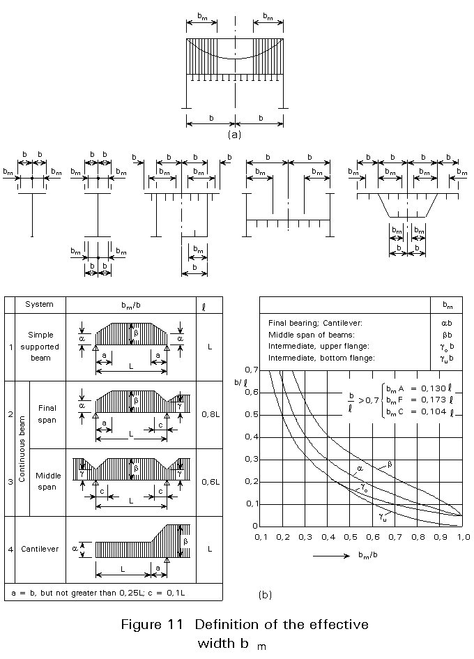
Most practical situations can be reduced to standard cases and evaluated using standard charts and tables, Figure 11b.
Most modern designs for railway bridges are for replacements to existing, worn out structures. The design is dominated by the need to complete the replacement and re-open the railway line within a very limited possession, usually a single weekend.
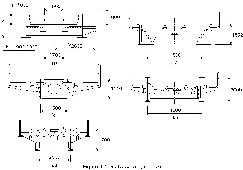
Where a new line or a realignment is being developed, the most important criterion is an unusual one for steel structures, that of noise. Some earlier steel bridges were constructed with rail bearers that provided more or less direct support to the rails (Figure 12a, b and c). Traditional ballast was eliminated. These structures have proven to be very noisy - certainly too noisy for situations near residential accommodation and probably too noisy for passengers. This problem has been overcome by reintroducing the ballast throughout the bridge, Figure 12d and e. The ballast has the additional benefit of ensuring that track maintenance and line alignment are similar both on and off the bridge.
× Provide support to local loads.
× Contribute to overall longitudinal and transverse bending.
× Stabilise the primary structure.
× Act as diaphragms.
× Assist in the transverse distribution of load between primary girders.
× Designed for fast construction during bridge replacement.
× Designed to support track ballast to minimise noise.
[1] Design Guide for Continuous Composite Bridges: 1 Compact Sections
SCI Publication 065, 1989.
[2] Troitsky, M. S., Orthotropic Bridges, Theory and Design, The Forms F Lincoln Arc Welding Foundation, 1987.
[3] Pelikan, W and Esslinger, M, Die Stahlfahrbahn Berechnung und Konstruktion. MAN ForschHeft, 1957, 7.
[4] Cusens, A. R. and Pama, R. P., Bridge Deck Analysis, John Wiley and Sons, London, 1975.
SCI Publication 084, 1991.