ESDEP WG 15B
STRUCTURAL SYSTEMS: BRIDGES
To introduce the design of arch bridges for railways and highways.
None
Lecture 15B.1: Conceptual Choice
Lecture 15B.2: Actions on Bridges
Lecture 15B.3: Bridge Decks
Lecture 15B.10: Bridge Equipment
Lecture 15B.12: Introduction to Bridge Construction
The principal types of arch bridge are described, highlighting both their differences and similarities. A discussion of the principal structural elements is followed by a summary of the means by which they can initially be sized by simple manual analysis. The important secondary aspects of behaviour are identified. Various methods of erection are described in outline.
An arch may be defined as a member shaped and supported in such a way that intermediate transverse loads are transmitted to the supports primarily by axial compressive forces in the arch. The arch form is intended to reduce bending moments in the superstructure and should be economical in material compared with an equivalent straight, simply supported girder or truss. The horizontal thrust is resisted by the foundation or by a girder or truss running longitudinally beneath the deck for the full length of the span.
The arch has long been acknowledged as an efficient and aesthetically pleasing structural form. (Conceptual design aspects are discussed in more detail in Lecture 15B.1.) However, a much wider choice of materials is available to the contemporary designer than was available to his Roman counterpart.
Table 1 gives a summary of the longest arch bridges. For further information and examples see [1] and [2].
Table 1 The Longest Arch Bridges
|
Bridge |
Span in metres |
Year of completion |
Location |
Other details |
| New River Gorge | 518 | 1977 |
USA |
Four lanes; truss |
| Bayonne | 510 | 1931 |
USA |
Four lanes, two side-walks;truss |
| Sydney Harbour | 509 | 1932 |
Sydney, Australia
|
(48,8m) wide; truss |
| Fremont | 583 | 1971 |
Oregon, USA |
Tied arch; four lanes; orthotropic deck; welded box girders |
|
Zdakov |
380 | 1967 |
Orlik, Czecho-slovakia |
Two-hinged arch |
| Port Mann | 366 | 1964 |
British Columbia, Canada |
Tied arch similar to Fremont Bridge |
| Runcorn | 330 | 1961 |
Mersey, England |
|
| Birchenough | 329 | 1935 | Sabi, Rhodesia | Alloy steel |
| Glen Canyon | 313 | 1959 |
Glen Canyon, Arizona, USA |
Deck is 213m above water level |
| Lewiston- Queenston | 305 | 1962 |
Niagara River, USA |
|
|
Hellgate |
298 |
1916 |
New York City, USA |
Rail bridge |
Steel arch bridges are generally used to support either highways or railways.
Typical spans for steel arches range from 50 - 500 metres.
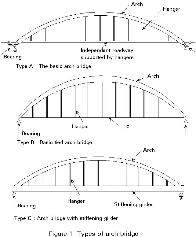
The nomenclature of the structural elements of an arch bridge is given in Figure 1.
Arch bridges can be distinguished by their structural actions. For reasons of convenience each type is given a code letter:
The basic arch bridge, with a predominating arch and with the thrust transmitted directly to the foundation. The arch is subjected to bending, shear and axial forces.
Type B: The basic tied arch bridge
The arch still predominates, but the thrust is resisted by tying the ends of the arch. The behaviour is very similar to Type A.
Type C: The arch bridge with stiffening girder
A predominating stiffening girder is subjected to bending moments and axial forces induced by the arch. The arch itself is mainly loaded in compression.
Though there is a difference in appearance, the mechanical behaviour of the three types is largely similar. In this lecture only the mechanical behaviour of Type C is discussed in detail.
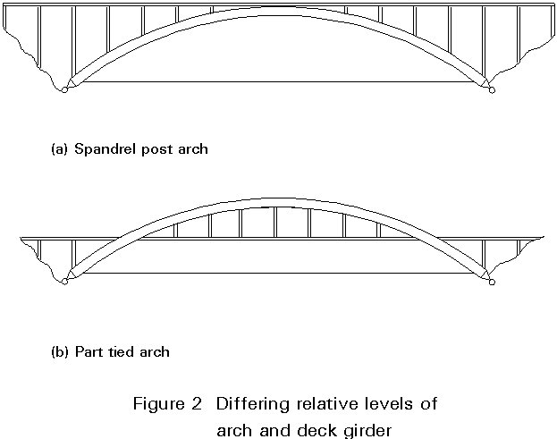
Figure 1 shows three situations in which the arch lies above the deck. Other equally valid arch forms exist in which the arch may be situated either entirely below (Figure 2a) or partly below (Figure 2b) the deck. Wherever the arch lies beneath the deck, the deck is supported by posts (i.e. compression members) rather than being suspended on hangers.
An elegant alternative is afforded by the use of inclined arches connected in the midspan region of the arch.
In the basic arch and tied arch configurations (Figure 1) vertical hangers are usually used. As these hangers are loaded in tension, rolled sections or cables can be used. If hangers are inclined, truss behaviour develops and upward wind loading may change tensile to compressive loading. Clearly this is unacceptable where cables are used. The most satisfactory solution to this problem is that the dead load of the deck should provide sufficient prestress to ensure that net compression never develops in the hangers.
Whilst tied arch bridge structures exist in which both girder and arch are subject to considerable bending moments, they are relatively uncommon and are not discussed further here.
Where a steep sided valley or gorge is to be crossed the spandrel post arch of Figure 2a provides a striking and appropriate solution. In flat terrain or where navigation clearances are to be achieved over significant proportions of the river width, one of the basic or tied arch arrangements of Figure 1 will generally be preferable.
Where multiple spans are involved, there is a view (voiced by Leonhardt [2]) that repetition of the spandrel post arch arrangement of Figure 2a rather than of the tied arch (Figure 1) is to be preferred on aesthetic grounds. A single tied or part tied arch can then be adopted on the main or navigation span, as used to good effect in the Rogue River Bridge in Oregon, America [2].
The tied arch bridge generally consists of the following structural elements:
The arch can be either a truss, box girder, plate girder or some form of hollow section (e.g. circular). Many of these structural elements are discussed in other lectures. No essential differences are to be expected arising from their use as an arch.
Ideally, for aesthetic reasons the arch should follow a smooth, continuous curved profile. However, overall curvature of the arch member may also be achieved by means of a series of short straight chords as indicated in Figure 3a. The hangers are attached at breaks of slope in the arch. In this form of arch out-of-plane forces are generated in the top and bottom flanges of the arch member, thus necessitating an internal cross frame or diaphragm (Figure 3a).
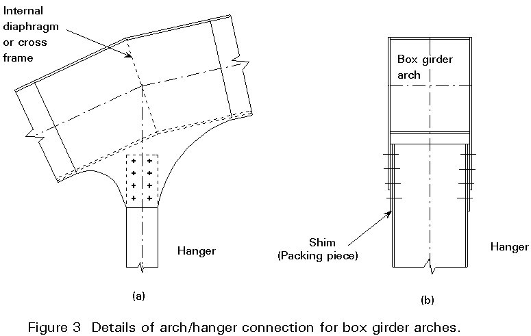
Where rolled or fabricated sections rather than cables are used for the hangers, connection of the hangers to the arch can be carried out using a detail in which splices are formed in extended web plates of the arch member at the joint (Figure 3).
Even if bracing between arches is present over the larger part of the span, it may have to be omitted near the ends of the arch to provide clearance for traffic, see Figure 4.
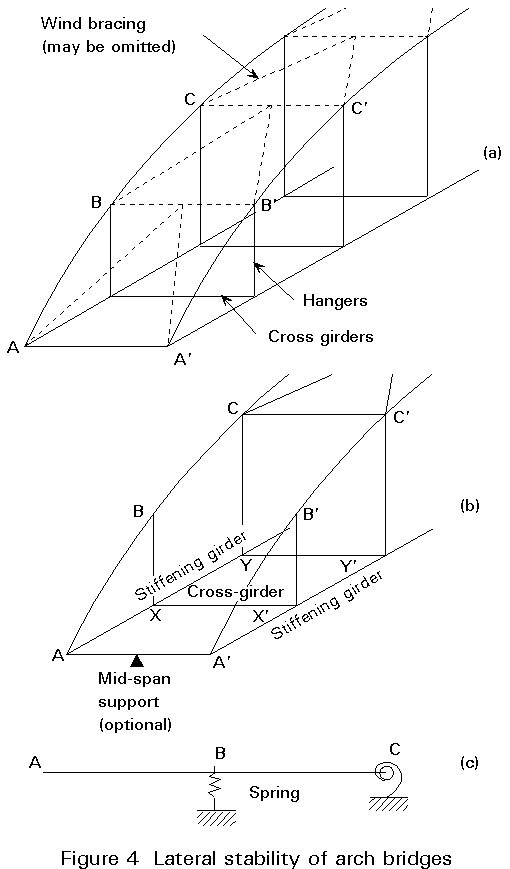
Where wind bracing is not provided, the lateral stability of the arch is somewhat more complicated to assess than for a truss, for two reasons:
The energy equation governing this problem and the method of solving it are similar to the approach for a truss. Computer analysis affords an alternative solution. In practice, frame action at CYY'C' and the bracing above CC', together with the restraint provided by the end portal CAA'C' (discussed in 3.4), will generally ensure the stability of points such as B, B'.
Rotation of the stiffening girder about its longitudinal axis effectively reduces the stiffness of the U-frames (e.g. BXX'B' in Figure 4b). To mitigate this detrimental effect, the end cross girder is sometimes supported at midspan (Figure 4b).
The girder can be made of:
Considering the tied arch more closely, it is to be noted that arch and girder are often in separate vertical planes; the arch is therefore connected eccentrically to the girder. Any such eccentricity must be taken into account in design.
For a box stiffening girder, or an open "top hat" section, an excellent connection between the arch and girder is obtained by using two splice plates, coinciding with the walls of the stiffening girder (Figure 5).
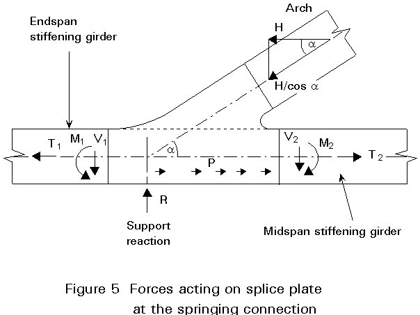
Each joint plate is loaded by:
The stress distribution in the plate is complicated. It may be obtained using finite element methods.
I-sections (welded or rolled), circular hollow sections or cables may be used for the hangers. Opinions differ about the optimum choice of section. Cables are made of high tensile steel e.g. Fe 1800. Due to the high stress levels which occur and the effects of creep, elongation occurs which is partly elastic (i.e. recoverable) and partly permanent. However, for highway bridges and railway bridges with or without continuous ballast, cables have been successfully used.
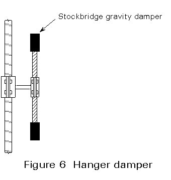
I-section hangers can be sensitive with respect to flutter whilst hollow sections and cables may vibrate as a result of vortex shedding. Annex A presents a method of ensuring that undesirable vibrations do not occur. It is often easier to reduce the effect of vibrations than to suppress them. The most dangerous vibrations are those with high kinetic energy, i.e. those with short wavelength occurring at high wind velocity. Such vibrations can be reduced by the use of dampers (Figure 6).
To support the arch laterally and to reduce the buckling length of the arch members, bracing is usually used for the central region of the arches. Wind forces and stability effects are transmitted to the supports by rigid end portals (Figure 7a).
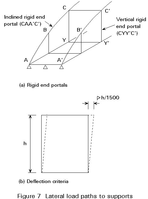
Although no stiffness requirements are generally specified, it is considered good practice to limit the maximum 'lozenging' of an end portal to h/1500 (Figure 7b).
Different methods may be adopted for transmitting these forces back to the supports.
The arch bridge is usually indeterminate. However, simple manual calculations can be used for initial design.
The tied arch is chosen here as an example. The reasoning can also be applied to most other types of arch bridge.
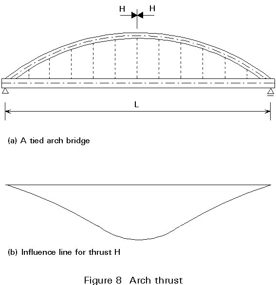
Consider the tied arch shown in Figure 8a. The influence line for the horizontal component of the midspan thrust in the arch, symbol H, is shown in Figure 8b. The line is symmetrical about midspan and its sign does not change. The greatest thrust clearly develops when the full span is loaded.
Next consider the behaviour of the bridge when subject to four important patterns of loading (Figure 9):
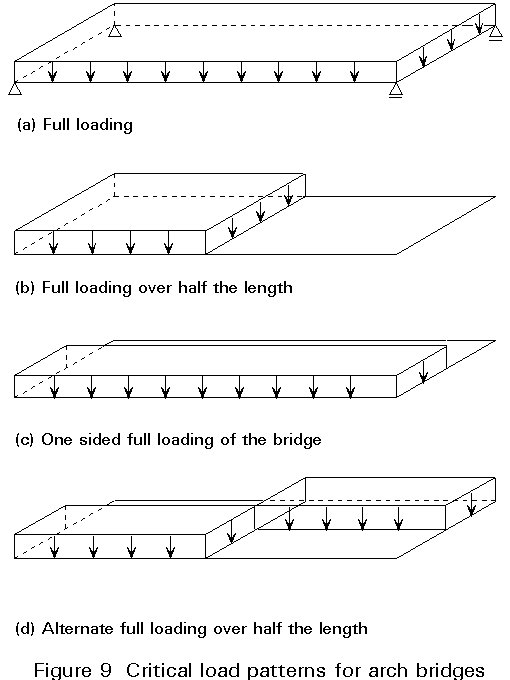
a. full loading
b. full loading over half the length of the bridge
c. one side of the bridge fully loaded
d. alternating full loading over half the length of the bridge.
In this case the thrust H reaches a maximum. From computer calculations it will be found that the stiffening girder acting in bending contributes only about 5% to the load carrying resistance of the bridge. As a result a very good estimate of the thrust can be obtained from:
H = ![]() (1)
(1)
where:
q is the uniformly distributed load
L is the span of the bridge
F is the rise of the arch, usually about L/7.
The half span of uniformly distributed loading 2q is equivalent to two superimposed loadings (Figure 10):
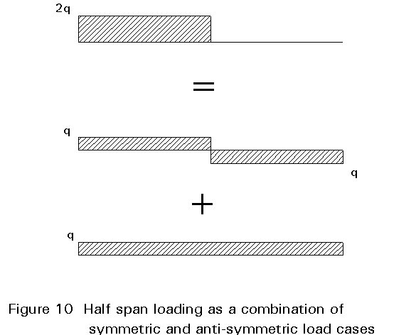
to the left: positive loading +q;
to the right: negative loading -q.
Full loading primarily generates a thrust in the arch and a compensating tensile force in the girder.
Due to the symmetry of the influence line, the second loading does not generate any thrust. As the deflection under this second loading is composed of two half waves, the girder can be considered to be composed of two parts with a "hinge" at midspan. The maximum bending moment is therefore approximately:
Mmax = ![]() (2)
(2)
This maximum bending moment occurs at L/4.
Again the equally distributed loading 2q can be considered as being composed of two superimposed loadings:
full loading on the other side of the bridge: -q
Again the full loading primarily generates a thrust, inducing a tensile force in the girder which is calculated from Equation (1).
The one sided loadings tend to lozenge the bridge cross-section causing horizontal lateral forces on the arch and deck. These forces create horizontal bending moments in the girders and deck. In an orthotropic deck the bending moment may lead to stresses greater than the allowable stress.
Again the equally distributed loading 2q can be considered as being composed of two superimposed loadings:
to the left: positive loading +q
to the right: negative loading -q
to the left: negative loading -q
to the right: positive loading +q
Again full loading primarily generates a thrust, inducing a tensile force in the girder, which is calculated from Equation (1).
Considering the deformations due to the second loading, in one of the main girders:
If a bracing is inserted, then the horizontal displacements impose an S-shape on the arch, with the inflection point at midspan. As a consequence there is a shear force in the plane of the bracing.
This shear force is rather moderate, even in large bridges. For the double track railway bridge across the Amsterdam - Rhine Canal, span 114m, the shear force at midspan is about 100 kN.
The above demonstrates that it is necessary to consider the bridge as a three-dimensional structure in the final design.
The discussion in the previous section only addresses the primary modes of behaviour of the arch bridge. There are several secondary actions that need to be considered in design.
The initial analysis has assumed that the connection between the hangers and both the arch and girder are pinned. In practice these connections are rigid and the displacements in the structure lead to bending moments in the hangers. Figure 11(a) shows typical influence lines. It can be seen that the greatest bending moments arise when the arch is partially loaded. The worst cases in this example are the shortest and the longest hangers. Figure 11(b) shows the displaced shape and distribution of bending moments in the shortest hanger. Moments in the hangers at midspan are subject to full reversal and are therefore most likely to influence fatigue life. Their absolute value is, however, low, justifying their neglect in the initial global analysis. (In the Amsterdam Rhine railway bridge the maximum bending stress was 80 N/mm2).
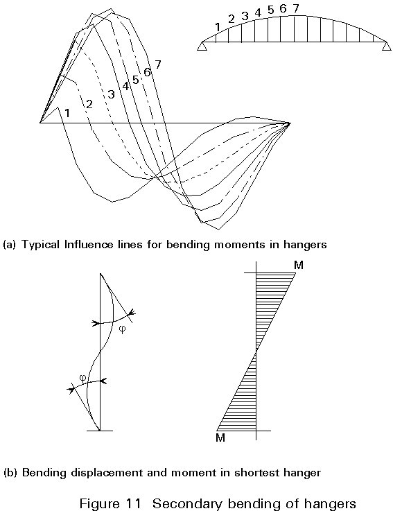
In order to reduce the magnitude of these fluctuating stresses it is possible to reduce the minimum second moment of inertia of the hangers by reducing the flange width.
The use of open grid steel decks on railway bridges is now very rare given the contemporary demand for the provision of ballast. In the few situations in which such a deck arrangement might still be considered, it is important that any adverse local effects in the deck arising from non-coincidence of the neutral axis levels of the stiffening girders and any longitudinal stringers or rail bearers should be allowed for and be combined with global effects. A detailed discussion of such effects is not warranted here; however, a description is given in Lecture 15B.4.
Hangers and long slender members are subject to wind induced oscillations. Annex A summarises the approximate methods of ensuring that vibrations of undesirable magnitude do not occur.
The main features of behaviour of arch bridges have been described in previous sections. It is therefore helpful to highlight the differences and similarities between the different types of arch bridge.
Type A and B: The hangers are loaded in tension by local live load and, of course, dead load.
Type B and C: The tensile force in the ties causes an elongation which affects the bending moments in the arch. Since a tie has a smaller cross-section than a stiffening girder, the elongation effect is greater for type B.
Type A: The elongation effect is assumed to be absent if the abutment carries the thrust.
Type A and B: It is impossible to omit the bracing between the two arches: the portals formed by connection of the hangers to the cross girders offer very little restraint to the arch to prevent instability.
The erection method adopted is determined to a large extent by local circumstances. As no universal solution can be given, some examples are discussed below.
The erection sequence for the tied arch railway bridge across the Amsterdam-Rhine Canal is shown in Figures 12 and 13.
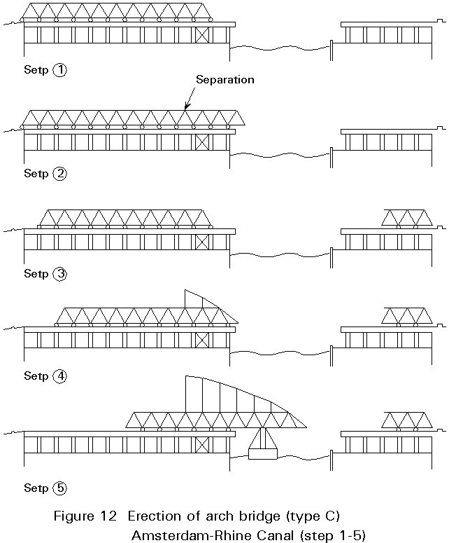
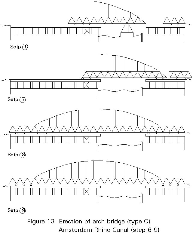
It is considered advantageous to use a Type C arch bridge, with a rigid girder, for a railway bridge. The girder including the deck can often serve as a working area for the erection of the arch.
For a tied arch it is sometimes possible to pre-assemble the bridge completely and erect the structure using pontoons. An example is the Van Brienenoord Bridge, across the Meuse, Rotterdam.
An arch without ties can be erected in the same way taking out the ties after erection of the bridge. However, the arch thrust causes some elongation of the ties, an effect which must be taken into account during fabrication and erection.
During erection of the bridge across the Waal, Nijmegen, a bridge that was erected subsequently at Dordrecht across the Meuse was used as a temporary working area.
[1] O'Connor, Colin: Design of Bridge Superstructures, Wiley, New York 1971.
[2] Leonhardt, F.: "Brucken/Bridges", The Architectural Press, London, 1982.
ANNEX A PRACTICAL MEANS OF ENSURING THAT HANGER VIBRATIONS ARE MINIMISED
Hanger Flutter in I Sections
The chance of undesirable vibrations is reduced to a large extent if the following condition, partly empirical and partly theoretical, is satisfied:
w
.b ³ 8 m/s (A1)where:
w
is the frequency due to bending or rotational vibration.b is the dimension of the hanger in the direction of the wind.
Note: "To a large extent" means that the possibility of vibration is not completely excluded. It is good practice to take precautionary measures to suppress visually disagreeable vibrations if they still occur.
The requirement given by Equation (A1) is quite onerous for very long hangers.
To use Equation (A1), it is necessary to calculate the bending (w'b) and torsional (w'r) natural frequencies.
w'b = 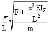 (A2)
(A2)
w'r = 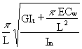 (A3)
(A3)
Im is the mass moment of inertia
Iy is the second moment of area with respect to the bending axis
It is the torsion constant
A is the cross-section area
Cw is the warping constant, ![]() y2 z2 dy dz
y2 z2 dy dz
F is the axial force in the hanger
m is the mass of the hanger per unit length
L is the length of the hanger
An important means of avoiding flutter is to ensure a sufficient difference between the two frequencies. Difference in frequencies can be achieved by:
If cables are used, flutter cannot occur as the torsional mode of vibration cannot occur.
Vortex Shedding
Cables and circular hollow sections can develop significant vibrations from vortex shedding. Vortices are generated from alternate sides of the cable with a frequency Fw given by:
Fw = 0,2 ![]() (A4)
(A4)
where:
v is the velocity of the wind [m/s]
D is the diameter of the cable [m]
0,2 is the Strouhal number
To avoid excitation due to vortex shedding, the cable frequency, Fc, should avoid a domain around:
Fc = 0,1 ![]() (A5)
(A5)