ESDEP WG 15B
STRUCTURAL SYSTEMS: BRIDGES
This lecture gives information on details and features particular to box girder bridges. The lecture is intended for engineers with some training.
Lecture 8.5.1: Design of Box Girders
Lecture 8.5.2: Advanced Methods for Box Girder Bridges
Lecture 15B.1: Conceptual Choice
Lecture 15B.2: Actions on Bridges
Lecture 15B.3: Bridge Decks
Lecture 15B.10: Bridge Equipment
Lecture 15B.12: Introduction to Bridge Construction
The history of box girder bridges is briefly reviewed. Their general design is discussed, examining economic span range, span-to-depth ratio, design of cross-section and selection of steel grade. Critical details are examined. The methods of analysis are summarised, with reference to the more detailed treatments in Lectures 8. Methods of erection are presented and the lecture concludes with a summary of the lessons that need to be learned from the box failures of the 1970's.
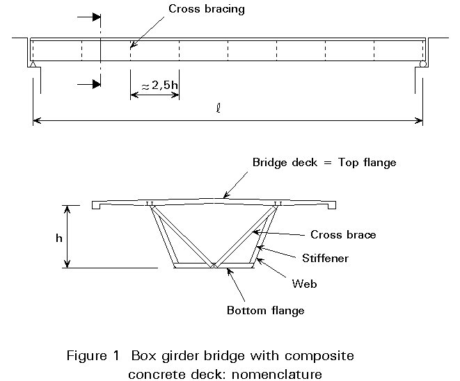
The nomenclature of the structural elements in a steel box girder is given in Figure 1 which shows, as an example, a single cell box girder with a composite concrete deck.
Until 1940 the structural possibilities for box girders were limited; structures had to be assembled from rolled sections, plates, and riveted connections.
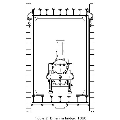
Notwithstanding these limitations, the first box girder, the Britannia Bridge (1850) with main spans 152 m, Figure 2, served as a model of what could be achieved with innovative design.
The basic concept of using hollow sections was only occasionally repeated with rivetted construction.
Note: A similar mechanism could occur by porosity in single run welds, e.g. in troughs in orthotropic decks. However, it is not common practice to use a double run. The porosity is accepted as it is.
With the development of electric welding and precision flame cutting, the structural possibilities increased enormously. It is now possible to design large welded units in a more economical way, e.g. box girders, using the techniques similar to those of shipbuilding.
A box girder consists of:
This basic cross-section can now be found in many bridges:
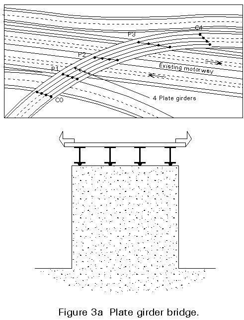
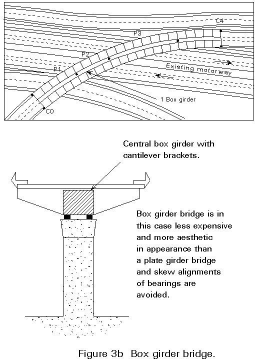
The great torsional rigidity makes a box girder a particularly appropriate solution where the bridge is curved in the horizontal plane, Figures 3a and 3b. Many bridges on European highways may serve as examples. Launching as an erection method is then still possible as long as the curvature is constant.
In wide cross-sections the box is sometimes subdivided into cells, Figure 4a. In such structures the bottom flange is not very efficient.
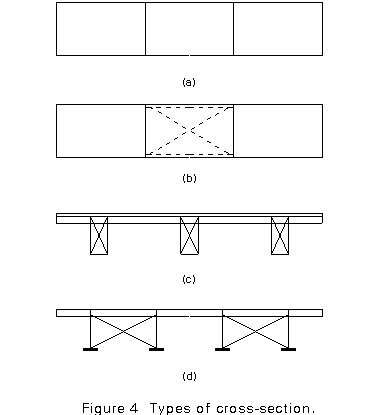
Alternatives are:
two cells on the outside,
a central "cell", consisting of cross braces connecting two outer cells and grids as deck plate, Figure 4b.
Strengthening and widening of existing bridges is an ever recurring problem. By its nature, a box girder offers excellent opportunities for reinforcement by prestressing or by additional plates welded to the bottom flanges.
So far only "closed" box girders have been discussed. However, a form of structure with great torsional rigidity has been known for a long time: the three dimensional truss. The stiffening girders of many early suspension bridges were sometimes made of a "box girder", with two, three or all walls consisting of plane trusses.
Box girders are suitable for longer spans than I-girders and allow larger span to depth ratios. The limits for competitiveness may vary due to local market conditions.
Steel or steel-concrete composite box girders are usually more expensive than plate girders because they require more fabrication time. They have, however several advantages over plate girders which make their use attractive:
Table 1 Span range for box girder bridges
|
Composite concrete deck (m) |
Orthotropic deck (m) |
|
|
Simple span |
20 - 100 |
70 - 120 |
|
Interior span of continuous girder |
30 - 140 |
100 - 250 |
Table 1 indicates economic span limits for road bridges.
The longest span so far is 300 m achieved in 1974 by the Costa e Silva bridge in Rio de Janeiro. It is always probable that the longest span existing has passed the limit of best economy.
The span-to-depth ratio will normally be around 20 to 25 for simple girders and around 25 to 35 for continuous girders. It is possible to reduce the depth, if necessary, without violating deflection limitations, at the expense of additional steel. The above ratios are valid for road bridges. For rail bridges the ratios should be smaller, say 15 and 20. It is advisable to check the most favourable span-to-depth ratio by trial designs.
A box girder may have vertical or inclined webs. It is cheaper to manufacture a girder with vertical webs. This section shape may be the best solution for a narrow road or a single track railroad.
A single narrow closed box girder can be positioned on the bridge centre line and completed with cantilever brackets (Figure 3b).
A combination of a wide deck on a short or medium span bridge favours inclined webs, Figure 1. For instance, a 13 m wide concrete deck without transverse prestressing requires a width of the box of 6 m at the top. If it were made with vertical webs the bottom flange would be much too wide to be efficient. Inclined webs reduces the width in a favourable way. Normally the webs are inclined 20 - 35 degrees from the vertical. In many cases inclined webs are chosen for aesthetic reasons.
There are several effects that make wide flanges inefficient. One is shear lag and another is local buckling of areas in compression. Further the minimum thickness specified in codes may often make the flange area excessive.
Plate widths of 3,3 m are readily available and some French or German mills produce wider plates, up to 5 m. (Greater widths are available with thinner plates.). If even wider plates are needed a longitudinal weld adds costs. In this case the longitudinal weld does not need to be a full penetration butt weld. It is generally preferable to adopt the maximum available width and avoid the longitudinal weld even if a slightly thicker plate would lead to less stiffening. This advice is valid for the bottom plate as well as the webs.
The best economy is achieved if sections can be fabricated in the full width at the shop. If the sections can be delivered by boat the only limitation is the handling equipment. Composite box girders will frequently be small enough to be shipped in one piece, also by road. Local restrictions for road transport should be checked. The normal width limit, 2,5 m, may be exceeded if special permits are requested, e.g. maximum of 4,5 m is allowed in Sweden. The costs of the escort should be checked.
The common steel grade for box girders is S355 with a yield strength fy=360MPa in the main structure and S235 or S275 for bracings. For long spans it is cost effective to use higher grades, e.g. fy = 460 MPa.
Since the higher grade steels are now thermomechanically processed, their use may be economically attractive provided that fatigue is not governing.
This section deals only with details typical for box girders excluding the deck. For decks see Lecture 15B.3 and for plates in general see Lecture 8.5.2.
Stiffeners are needed on the bottom flange at least at the piers where it is in compression and sometimes also on the webs. In designing an economical girder, the cost of handling and welding the stiffeners has to be taken into account. With increasing labour costs the tendency is to have fewer stiffeners and thicker plates. For instance it is common in Sweden not to use stiffeners on webs until the depth exceeds 2,5 - 2,8m (1 man-hour equals 60 kg steel). National practice varies in this respect. Contractors also have their own preferences.
The bottom flange will in most cases have a very small effective area if it is not stiffened at the support. An efficient profile is the cold-formed trapezoidal stiffener. One to two will be sufficient if they are made big enough.
If the bridge is to be erected by launching or cantilevering, it is often necessary to stiffen the bottom flange along the whole girder in order to resist the hogging moments during erection.
At the supports considerable forces from torque and shear have to be transmitted to the bearings. The recommended solution at piers is a diaphragm, i.e. a steel plate transverse to the girder. The plate is designed to carry the shear from the torque and is strengthened locally in order to carry the support reactions. The diaphragm at the pier sections prevents deformation of the section (distortion of the box cross-section). If the bottom flange is narrow it may be necessary to put the bearings outside the flange and to provide the webs with external stiffeners.
In order to prevent cross-section distortion, the girder is provided with intermediate cross frames (see Figure 1). The webs and bottom flange have transverse stiffeners at these sections. The intermediate transverse stiffeners are made of flats or strips of plate when cross bracings are used. For the intermediate frames, the bracings can be omitted if the rigidity of the cross frames constituted by web and flange stiffeners is enough. The intermediate transverse stiffeners are made of a T section when bracings are not used.
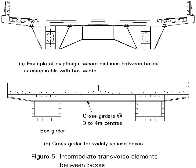
The design of the transverse elements between two longitudinal box girders are generally subject to important stress variations under eccentric live loads. Their design is generally governed by fatigue considerations. Large, widely spaced diaphragms may be adapted, Figure 5a. Alternatively cross girders at 3 to 4m spacings may be adopted that support a concrete or orthotropic steel deck as shown in Figure 5b.
As a box girder is torsionally rigid it is possible to use a single bearing at one or more supports and to transmit the torque to where the foundations are suitable to resist it. This is particularly common if the bridge is highly curved. The single bearings may be supported by slender columns.
At each end of the bridge, there are generally two bearings if the bridge consists of a single box girder. Special attention has to be paid in this case to ensure sufficient distance between the two bearings.
Another consequence of the torsional rigidity is that extra care has to be taken to get the correct support reactions when there are two bearings at each support. One way of doing this is to let the box rest on jacks with predetermined loads and to fix the permanent bearing when the jack loads are correct.
If the bearings on the pier are under the diaphragm, care must be taken to ensure that thermal moments do not lead to longitudinal eccentricity occurring at the bearings. Additional stiffeners may need to be provided.
The interior of a box girder is exposed to far less risk of corrosion than the outside. Hence, the interior corrosion protection can be made simpler or even omitted completely. There is always a possibility of water leaking into the box, especially if the deck is made of concrete. For this reason the box should be equipped with a dehumidifier to keep the air dry. This is an inexpensive precaution.
White painting or very light colours should be used for the interior to facilitate future inspections.
A box girder may be analysed as a beam subjected to bending, shear and torsion. Simple beam theory is however not an adequate tool and additional considerations are required, e.g. shear lag, warping and distortion of the cross-section [1]. For details, see Lecture 8.5.1.
The additional stresses caused by cross-section distortion depend largely on the distance between the cross braces. With a sufficiently small distance these stresses may be neglected. National practice varies on this point.
A torque is primarily carried by shear stresses corresponding to the theory of pure torsion. These stresses are readily calculated from the assumption of a constant shear flow in a single cell box. In addition restrained warping changes the distribution of shear stresses slightly and, more important, gives rise to longitudinal stresses which add to the bending stress. The stresses due to restrained warping are not very large and an approximate estimate is sufficient, see Lecture 8.5.2.
The cross bracings act to restrain cross-section deformation. The loads on them arise from eccentric loading and the loads can easily be calculated if the cross-section is assumed to have zero stiffness for deformation in its own plane or, an equivalent assumption, hinges are assumed in the corners. The loads are assumed to be carried by flanges and webs acting as beams with rigid supports at the cross braces. The support reaction from those fictitious beams are the forces that are carried by the cross braces. For details see Lecture 8.5.2.
When intermediate bracings are omitted, special attention should be given to the design of the corners of the unbraced cross frames which should resist the bending moment in the plane of the cross frame. (The steel box girder works in the same way as pre-stressed concrete box girders). In this case web and flange T stiffeners are designed for this purpose. The design of the corners is generally governed by fatigue considerations.
When the intermediate cross frames do not support traffic load directly, they are in general lightly stressed.
Box girders may be erected with normal methods such as launching or cantilevering. If the bridge is curved in a circle, launching works without complication. If the box has an orthotropic deck it is rigid enough even for highly curved bridges. However, boxes with composite concrete slabs are normally erected as an open trough. This open shape is torsionally very soft. The shear centre is unusually far under the centre of gravity, so that the section will deflect substantially, vertically as well as horizontally, under selfweight complicating the launching. Further, the casting of the concrete slab creates additional eccentric load and further deformations and stresses if the box is curved and open.
One solution is to provide the box with horizontal bracings between the top flanges. The bracings must be designed to avoid interference with the casting of the concrete slab. These diagonals may be temporary if it is deemed worthwhile to remove them after casting the slab. Another possibility is to use lost shuttering.
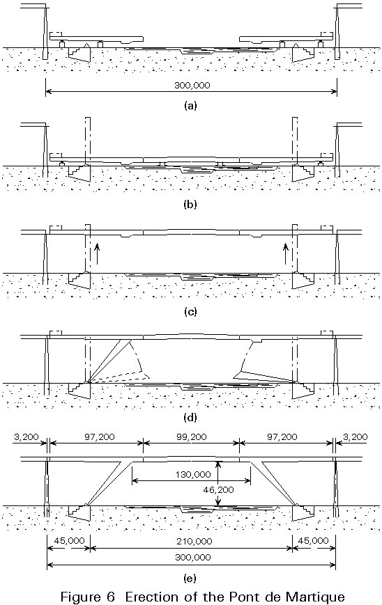
An ingenious system was used for the erection of the Pont de Martigue, Figure 6. The girder was fabricated in three parts. The two end parts were placed below the abutments and the third part mounted in between. Next the stiffening girder was lifted by two portal cranes, the legs mounted and the leg to girder connections made. The gaps between the sloping legs and the girder were closed, using ballast and the portal cranes.
Structural failures occur as a result of human failures. Moreover human failures have the inclination to repeat themselves.
During the period 1969-1971, several accidents happened with box girder bridges, all during the erection stage:
These four cases are briefly discussed below:
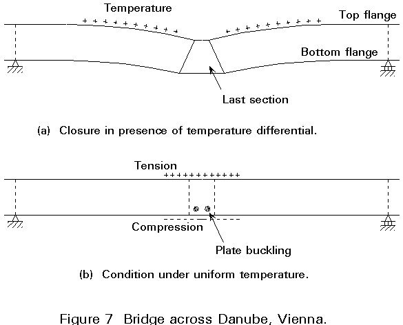
Vienna
The erection of this bridge proceeded without problems by cantilevering from both sides. The final gap was closed on a hot summer day. The deformations of the bridge due to temperature expansion are shown in Figure 7. During the night an evenly distributed temperature was restored. The bridge straightened, leading to plate buckling. The buckling was corrected and no collapse occurred.
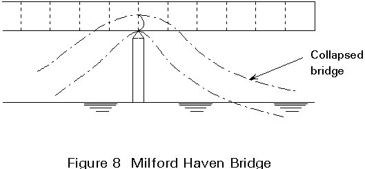
Milford Haven
The midspan of this bridge was erected by cantilevering. With this method of erection the cross frame above a pier suffers extra loading due to the cantilevering part. This load causes no problem provided the diaphragm is designed to carry it. This was not the case. The bridge collapsed, Figure 8.
Melbourne
The stiffening girder of this cable stayed bridge consisted of three cells. For erection, the box was divided into two parts longitudinally, Figure 9. On each side of a pier one part of the box was assembled, hoisted to the correct level and shifted into the correct position to be connected.
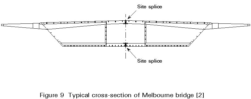
Some complications:
The last two problems were solved by putting ballast on top of the bridge. The difference in overall deflection disappeared but buckling of the cantilevering top flange increased. To solve the problem of the final buckle, some high strength friction grip bolts were taken out to remove the incompatibility in flange length, with the disastrous result of passing the ultimate load carrying resistance. The bridge yielded and collapsed 50 minutes later [2].
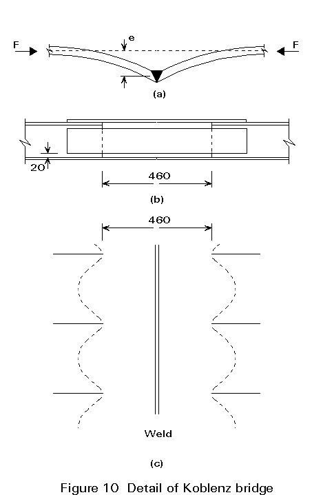
Koblenz
Cantilevering was used as the erection method and again a collapse occurred. The failure was due to the coincidence of three unfavourable aspects, each of which separately would, most probably, not have caused the collapse.
The accidents in the United Kingdom particularly led to a rigorous investigation programme [3]. In 1974, the 'Merrison Rules' were issued, a code giving recommendations on calculation and erection of box girders [4].
[1] Stevin Reports 6-75-16 and 6-76-14:
Stresses in box girders due to
- torsional warping (report 6-75-16)
- distortional warping (report 6-76-14).
[2] Report by the Royal Commission into the Failure of West Gate Bridge, 1971.
[3] Steel Box Girder Bridges. Institution of Civil Engineers, 1973, ISBN9901948 76 4.
[4] Merrison Report. Inquiry into the Basis of Design and Method of Erection of Steel Box Girder Bridges. Report of the Merrison Committee. HMSO, 1993.