ESDEP WG 15B
STRUCTURAL SYSTEMS: BRIDGES
Lecture 4A.4: Corrosion Protection of Bridges
Lecture 15B.1: Conceptual Choice
In addition to the load carrying structures that make up the bridge deck, bridges also include a number of items of equipment which are essential to their service, function and life duration.
The choice of these items and installations depends not only on their initial cost, which may reach 10% of the total construction cost, but also on the operating cost related to their routine maintenance and possible replacement.
The items contribute to the length of life of the structure and as a consequence, they should not be the origin of problems that may affect the resistance of the bridge.
Bearing systems provide the mechanical fastening between the main load carrying members (main girders, arches) and the bridge supports (piers, abutments, foundation blocks, etc.). They contribute therefore to the functioning of the bridge as a whole.
The function of a bearing system is to transmit to the supports:
In doing so, the bearings must accommodate:
The designer must choose the types of bearing in each bearing system to suit the action effects and degrees of freedom required at each connection between the main members and the supports.
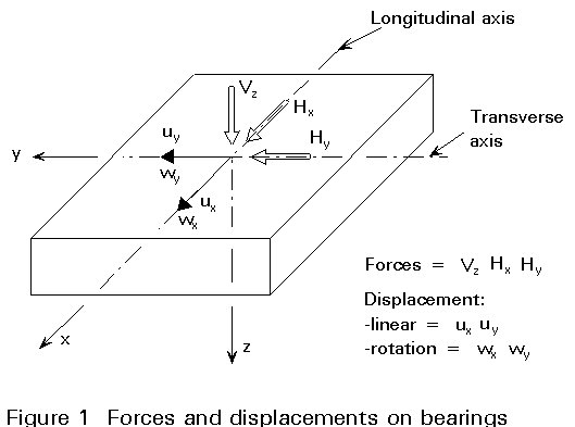
In general, the forces and displacements on a bearing are as shown in Figure 1. It is conventional to define the X axis as 'longitudinal' and the Y axis as 'transverse'.
As a general rule, a bearing system includes three kinds of bearing:
The number and layout of the three kinds of bearing is a key feature of the bearing system for a bridge.
In most cases the bearing system will be indeterminate. For a simple span the arrangement might be as shown in Figure 2a. Note that only one fixed and one unidirectional bearing are required. All others should be multidirectional (or 'free') for the system to be determinate.
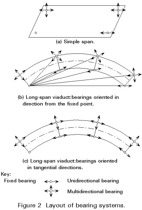
For a longer bridge, for example a curved viaduct, it may be necessary to provide lateral restraint at each intermediate support, as well as at the ends. Then two alternative arrangements are possible. In the first, Figure 2b, unidirectional bearings are arranged radially from the fixed bearing; in the second, Figure 2c, they are arranged tangentially. Both of these two systems are indeterminate and this must be taken into account in the global analysis of the structure.
There are four distinctive groups of bearing whose differences result from the structural materials used and from their structural behaviour.
These bearings function through direct contact between steel elements. Originally executed in cast steel, steel bearings are now fabricated from structural steel plate and bars.
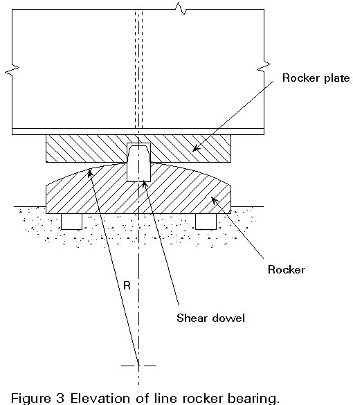
Linear bearings provide support through contact between a flat surface and a cylindrical one. The line contact allows rotation about one axis, usually the transverse axis, Wy.
Restraint against modest horizontal forces is provided by a shear key, often in the form of a dowel.
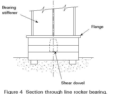
Rocker bearings consist of a lower rocker bearing (usually set in the concrete) and an upper rocker plate fastened to the main girder. Horizontal forces are transmitted by a shear key (Figures 3 and 4).
Roller bearings comprise one or several solid steel cylinders (or rollers) put between two parallel rocker plates, so that relative displacement in the X direction is made possible by rolling action. Small linear shear keys are used to resist the transverse forces Hy (Figure 5). To ensure that the roller axis does not skew in service, toothed guides are usually provided on the ends of the rollers.
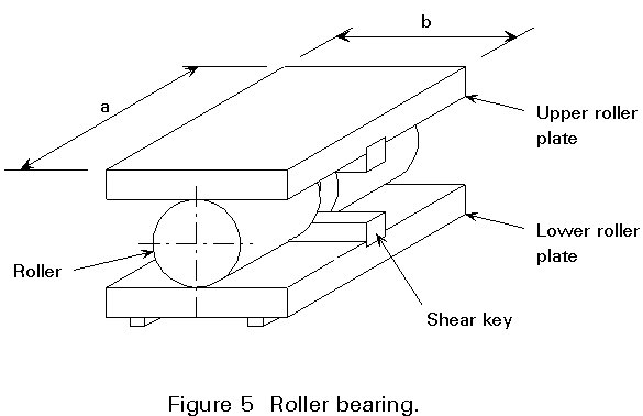
The minimum radius R of the cylindrical surface is determined by the contact pressure between the cylinder and the flat surface.
The elastic stress between a cylindrical and a flat surface is given by the Hertz formula:
sc = 0,418 ![]()
where:
V is the reaction
b is the length of contact line
E is the modulus of elasticity
R is the radius
Although this formula is applicable to an elastic condition, it has been found that it is satisfactory to allow the Hertz stress to be limited to values in excess of unaxial yield. Typically, the limitation for cylindrical rollers is:
sc £ 1,7 su
where:
su is the ultimate tensile strength of the steel.
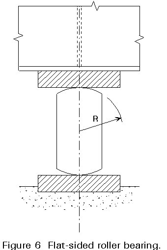
Where a larger roller is required but the longitudinal movement is small, a flat-sided roller can be used (Figure 6).
Sometimes bearings are required which offer multi-directional freedom of rotation. In such cases, recourse is necessary to a spherical hinge produced by a point bearing
plane/spherical contact point bearing (Figure 7)
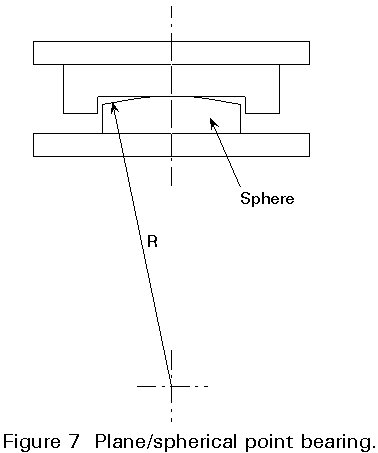
The contact pressure between a sphere and a plane is given by the Hertz formula:
sc = 0,388 ![]()
Typically the limitation on stress is:
sc £ 2,1 su
double spherical point bearing (Figure 8)
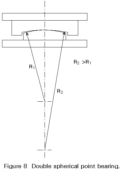
For a double spherical contact, the pressure is given by:
sc = 0,388 ![]()
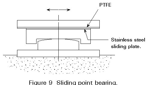
In addition to a spherical bearing contact, these bearings include a (uni- or multi-directional) sliding plane. Sliding occurs between a stainless steel (inox) insert and a PTFE plate (Figure 9).
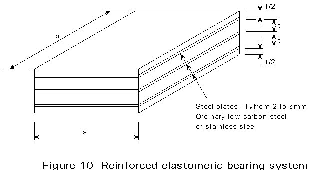
These bearings are essentially non-isotropic rectangular blocks which can resist:
Each bearing consists of several elastomer layers of various thicknesses, 8 to 20mm, glued together with 2 to 5mm thick steel plates (Figure 10).
Half-fixed simply supported bearings
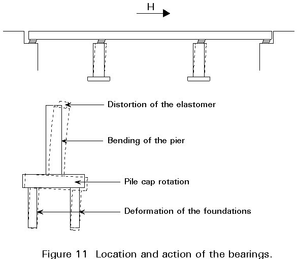
This type of bearing offers resistance to horizontal forces and displacements as well as carrying vertical loads. To do this the bearing must be securely fastened to the bridge structure and to the bearing supports.
In the bearing system, the horizontal forces are distributed in proportion to the combined stiffnesses of the bearings and of the piers and foundations (Figure 11).
This type of bearing is suitable provided the height of the block in relation to horizontal displacement is rather low. Beyond a certain height, the block becomes unstable.
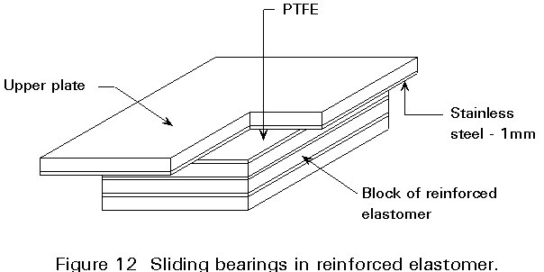
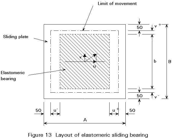
Elastomeric sliding bearings
When horizontal displacements are large, elastomeric bearings can be used with a sliding surface.
This is achieved by providing a stainless steel (inox) plate sliding on the upper face of a PTFE plate glued to the block of reinforced elastomer (Figures 12 and 13).
Pot bearings consist of a plain elastomer enclosed in a metal cylindrical pot. The upper face of the pot is a piston cover freely installed in the pot and bearing on the elastomer (Figure 14).
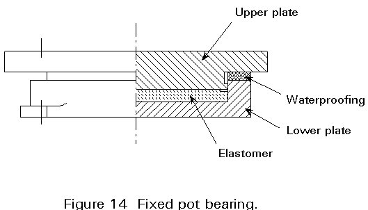
The elastomer enclosed in the pot distorts under constant volume and behaves as a fluid. It withstands both high pressures (25 MPa) and rotations (1/100 radians) because of zero shear stresses. This type of bearing effectively offers multi-directional freedom of rotation.
Pot bearings are less bulky than ordinary elastomeric bearings and give a higher performance. They are widely used.
Horizontal freedom is obtained by addition of a sliding plane (stainless steel-PTFE) on the piston cover (Figure 15).
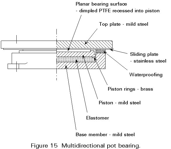
A sliding uni-directional bearing may be obtained by the addition of an exterior or interior guide.
This type of bearing is an all-steel construction somewhat similar to the pot bearing but with the elastomer replaced by a convex spherical cap sliding on a concave spherical element (Figure 16).
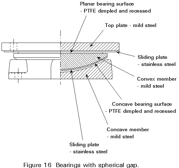
As before, introduction of sliding plane gives minor multi-directional freedom of displacement.
The stability over time of a bearing system depends largely on careful installation:
In association with the deck slab, finishes consist of:
The waterproofing course should protect the slab against any penetration of water which may contain more or less aggressive agents mainly, from the salt used for de-icing the carriageway (Figure 17). These agents of various origins may be harmful to the slab concrete, but even more detrimental to the steel reinforcement bars causing corrosion.
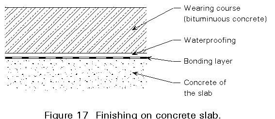
A good waterproofing course may thus contribute to the life of the structure.
Several techniques may be applied:
After descaling of the steel plate and immediate application of a bonding varnish, the waterproofing is added as a course of elastomer bitumen of about 3 - 5mm thickness (Figure 18).
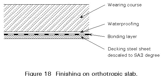
The waterproofing layer is continued under the footway and covers all the upward (safety fence support, kerbstones) and downward (gutter channels) parts.
The thickness of the wearing course varies from 6 to 10cm. To obtain satisfactory performance of the wearing course requires a good preparation of and bonding to previous course with strict observance of the prescribed hygrometric conditions. Where the slab is flexible it is necessary to ensure the wearing course has sufficient fatigue strength and is laid to the specified thickness.
The evenness of the surface as well as the continuity of the profile provide a smooth surface for traffic, reduce mechanical vibrations of the traffic, and avoid the formation of ruts and surface deterioration due to the winter frost.
The wearing course consists generally of bituminous concrete.
The common systems make use of specific compositions and spreading procedures which take into account the slab flexibility and fatigue behaviour. The systems used are a special material, which is made up of a bituminous concrete with a proportion of binder to confer a satisfactory plasticity to the course.
Expansion joints provide continuity of the road surface at the interface between the bridge deck and the abutments.
An expansion joint must be able to accommodate a range of movement, opening and closing, from its 'neutral' position, or critical setting.
The range of movement, i.e. the maximum displacements at open and closed positions of the joint, depends on several factors:
(i) linear thermal expansion and contraction of the bridge deck:
Dl1 = L.l.DT
where:
L is the distance from a fixed bearing
l = 1,1 . 10-5 per °C for steel
DT is the difference between extreme and neutral or setting temperature of the bridge.
(ii) horizontal displacements resulting from rotations about a transverse axis under service loads. At any supports:
Dl1 = q. h
where:
q is the rotation
h is the distance from the neutral axis.
Note that the displacements due to rotation both at the fixed bearing and at the expansion joint should be considered.
(iii) long term deformation of the concrete slab (shrinkage and creep)
(iv) horizontal displacements due to the braking forces and the flexibility of the "fixed" bearing.
The total range required will determine what types of joints are suitable. Joints must be set carefully, taking into account the temperature of the bridge at the time of setting and the opening and closing movements (which are not usually equal) from the neutral positions.
Designers need to consider the following points:
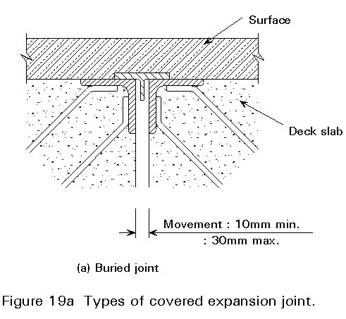
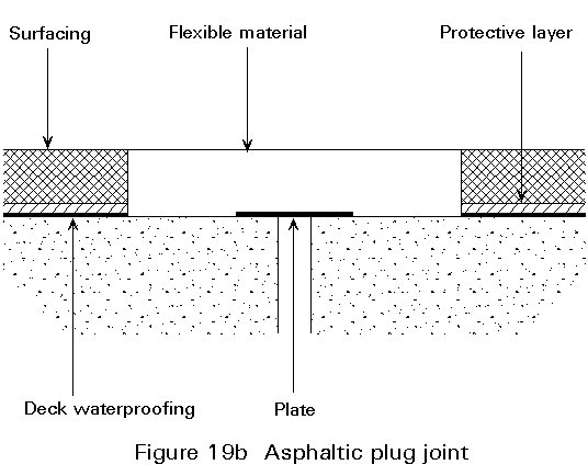
There are various technical solutions for expansion joints. The differences between the types relate to the amount of movement or displacement between the open and closed positions at the break.
This type gives a very comfortable riding surface, but the capacity of movement is restricted to 30mm. Only light or semidense traffic can be carried (Figure 19).
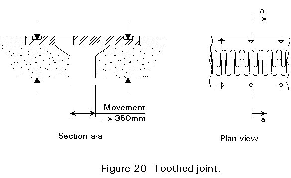
Two thick and firmly anchored sheets slide one into the other. They are in the form of straight or biased teeth which allow movements of 25 to 350mm (Figure 20). Larger joints require intermediate support of the teeth.
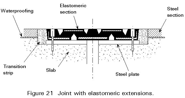
An elastomeric profile with steel plate inserts is fastened on two steel plates and anchored in the slab. Movements of up to 300mm are possible (Figure 21).
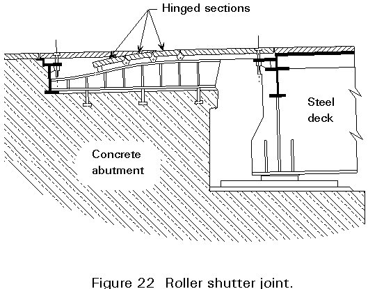
This joint consists of a series of hinged shutters, side by side. Each shutter consists of a train of linked plates sliding on a guide. Large deformations of 1m or more are possible (Figure 22).
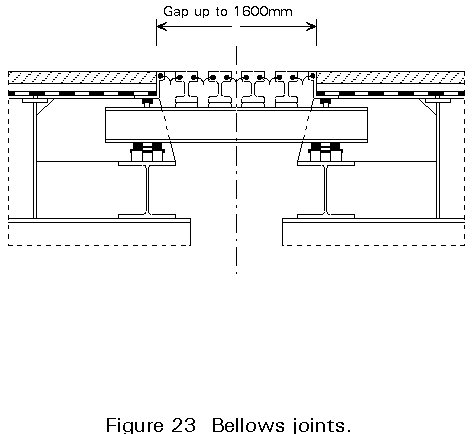
These joints consist of a series of transverse steel beams linked with flexible strip seals (Figure 23). Each steel beam is supported on girders or joints below the beams. Movement is accommodated in 'accordion' fashion as each of the seals flexes. The number of beams can be increased in a modular way so that movements of up to 800mm can be accommodated.
Parapets are necessary to protect both the users and the carriageways and railways. There are several types:
This equipment which is needed to meet general safety requirements, has to conform to detailed specifications. Acceptance by official inspection bodies is usually based on full scale testing.
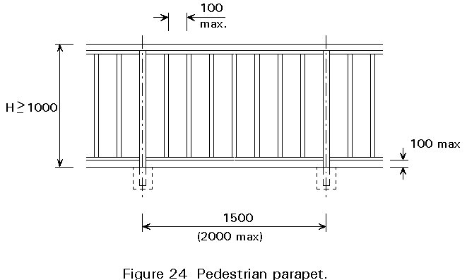
Pedestrian parapets are dedicated to the safety of people. Their shapes vary depending on their use and requirements of appearance.
Whether made of steel or aluminium alloy, all pedestrian parapets should conform to the same strength and safety requirements (Figure 24).
To be efficient, both sliding rails and barriers should:
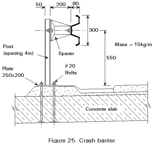
Crash barriers are usually bolted to the structure through an anchorage incorporated in the deck slab. The fastening is designed to ensure the structure is not damaged in case of an accident so that a quick and easy repair is possible (Figure 25).
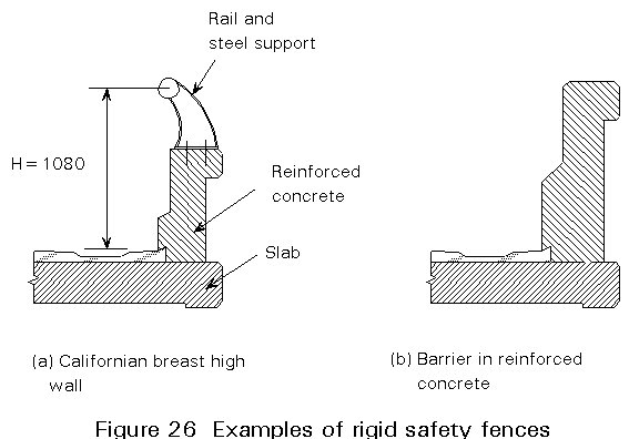
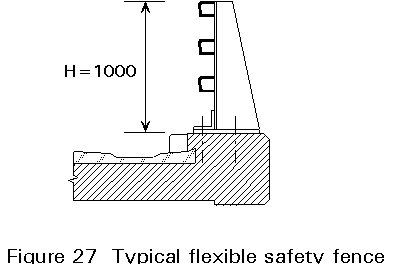
Depending on their purpose and the structural materials of which they are constructed, safety fences may be of various types:
Depending on the ambient atmospheric conditions, steel corrodes naturally and continuously and the resulting corrosion affects its service life.
As a result the protection of steel from possible electro-chemical corrosion is absolutely necessary.
Because of the importance of this problem, Lectures Group 4A are dedicated to corrosion protection.
The durability of the bridge as well as the users' safety also depend on good drainage of the deck (Figure 28).
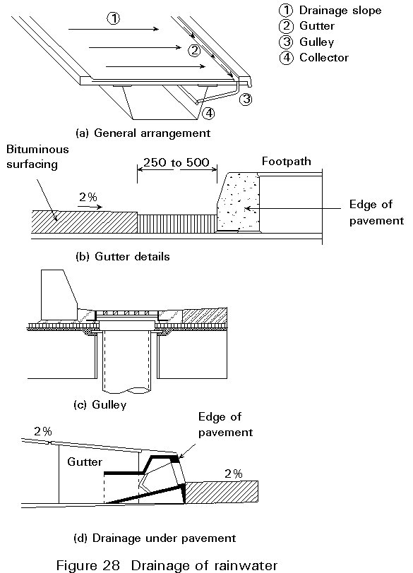
Drainage is carried out by means of:
The fascia are built on the deck edge and perform several functions (Figure 29):
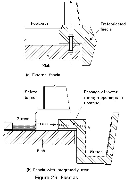
The current tendency is for the fascia to have essentially a decorative role. Fascia are therefore dealt with as both a light and aesthetical cladding element.
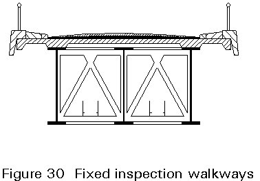
Inspection facilities giving access to all the parts of bridge structures are required because of the need for periodic visits to the structures for inspection and maintenance purposes.
There are three types of inspection facility:
Fixed installations are service platforms located in the beam grillage of the bridge structure (Figure 30).
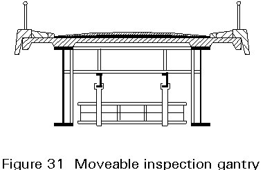
A motor-driven platform gantry moves along tracks fixed the full length of the bridge. Retractable and flexible elements allow access to both exterior and underside of the overhangs (Figure 31).
Clearances are provided with design so that the bridge deck can be reached and the piers can be passed.
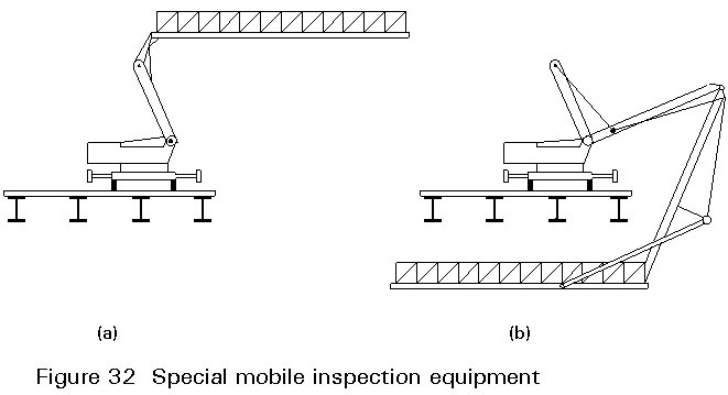
Special pieces of equipment are available, such as telescopic arms mounted on lorries or trucks which are parked on the carriageway. Such mobile equipment is economic if the equipment may be used on a large number of structures (Figure 32).
The global design of a bridge structure is first of all determined by the geometrical and geotechnical conditions of the site, the nature of the route, the clearances and the construction conditions.
The overall design should integrate the various pieces of equipment. They may generate stresses and constraints as follows:
They take up space and require incorporating into the structure with adequate reinforcements and anchoring points. Consideration needs to be given to their safe erection.
The weight of the equipment is one of the non-negligible parts of the dead load of the structure.
The forces to which some of the pieces of equipment are subjected, e.g. passage of axles over expansion joints, impacts on parapets, load transfer on bearing systems, generate significant stresses in the secondary structure.
The design of the fascia and parapets should be in harmony with the bridge structure.
In view of the needs for inspection, maintenance or replacement of structural members of the bridge, sufficient space for the access facilities should be provided.
A satisfactory project results only if all these factors are taken into account.
VEB für Banuregen, Berlin, 1974.
Bridges, John Wiley and Sons, New York. 1979.
McGraw-Hill Book Co., New York. 1985.