ESDEP WG 15B
STRUCTURAL SYSTEMS: BRIDGES
To introduce the designer to the principal conceptual choices that have to be addressed for the design of successful, economic steel and composite bridges.
None
Lecture 1B.6.1: Introduction to Design of Steel and Composite Bridges Part 1.
Lecture 1B.6.2: Introduction to Design of Steel and Composite Bridges Part 2.
This lecture emphasises the importance of the correct conceptual design of bridges. After a brief introduction on the different types of bridge, it highlights the influences that the bridge function and other factors may have on the selection of correct structural form. It also addresses the more detailed choices that have to be made as the design is developed.
"If you get the concept right, the design will be right". A trite statement, but one which contains a considerable element of truth (provided, of course, that the development of the concept is carried out correctly). If the concept is wrong, it will lead at best to a less than optimum design, or at worst to much abortive work or a design quite unsuited to its location. Conceptual design does not involve detailed calculations; indeed, in most circumstances, an experienced designer would probably be able to produce a safe and economic design from previous experience and would only use detailed calculations as a final check or for "fine tuning".
The purpose of this lecture is to give an inexperienced designer some guidance on the conceptual choices which have to be made. It is deliberately couched in general terms and makes no specific use of particular national or international standards for bridge design. In addition, many of the concepts described could be designed in either steel or concrete; in such cases, the emphasis is placed on steel construction.
Before attempting to describe how a designer approaches his task, it is useful to distinguish in very broad terms between a number of bridge types. (A more detailed catalogue of the types of bridges is given in Lecture 1B.6.1: Introduction to the Design of Steel and Composite Bridges Part 1. Their design is discussed in the remaining Lectures 15B.
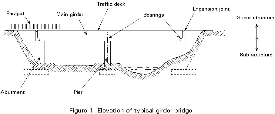
By far the majority of bridges are of this type. The loads are transferred to the bearings and piers and hence to the ground by slabs or beams acting in flexure, i.e. the bridges obtain their load-carrying resistance from the ability of the slabs and beams to resist bending moments and shear forces. Only for the very shortest spans is it possible to adopt a slab without any form of beam. This type of bridge will thus be referred to generally as a girder bridge. As can be seen in Lecture 1B.6.1, a wide range of structural forms is possible. Figure 1 indicates a typical elevation of a girder bridge with a number of terms being defined.
This type can be further subdivided into those bridges in which the primary axial forces are compressive (arches) and those in which these forces are tensile (suspension bridges and cable-stayed bridges). Such forces normally have to be resisted by members carrying forces of the opposite sense. Figures 2a to 2d show the basic structural systems for some typical layouts.
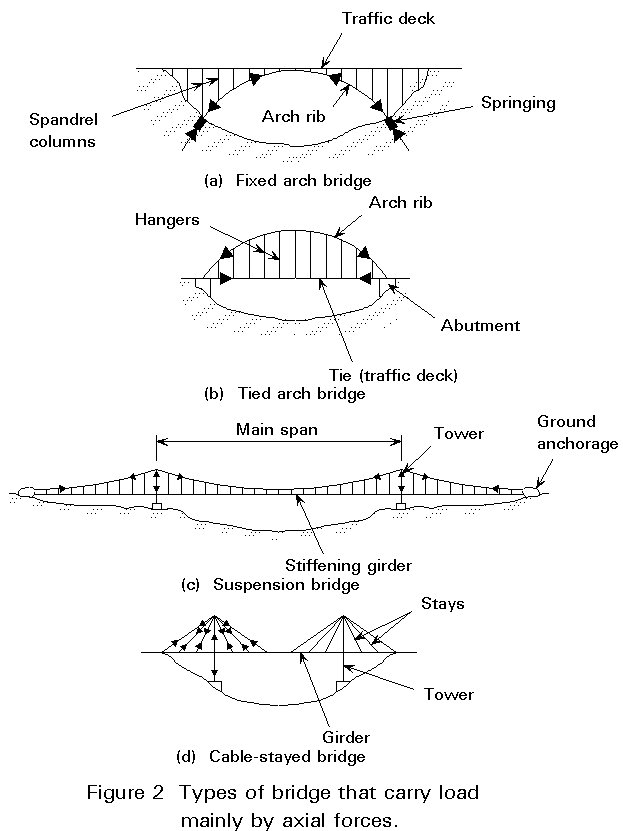
It must not be thought that flexure is immaterial in such structures. Certainly, in most suspension bridges, flexure of the stiffening girder (see Figure 2c) is not a primary loading in that overstress is unlikely to cause overall failure; however, in cable stayed bridges (particularly if the stays are widely spaced) flexure of the girder is a primary loading. Similarly, in arch bridges, non-uniform loading of the rib can cause primary bending moments to be developed in it and may well govern the arch design.
Truss bridges are not specific bridge forms in themselves - rather trusses are used to perform the functions of specific members in one of the types above. For example, a girder in flexure or an arch rib in axial compression may be designed as a truss rather than as a solid web plate girder. A truss used as a girder in flexure carries its bending moments by developing axial loads in its chords, and its shears by developing axial loads in its web members. Definitions can become somewhat blurred, e.g, a tied arch (see Figure 2b) can sometimes be considered to act as a truss girder, particularly if the hangers are inclined to form a triangulated system.
A bridge has to carry a service (which may be highway or railway traffic, a footpath, public utilities, etc.) over an obstacle (which may be another road or railway, a river, a valley, etc.) and to transfer the loads from the service to the foundations at ground level. The functional considerations that have greatest influence on conceptual choice are:
It is not possible to place these considerations in any particular order of importance; the relative importance is likely to vary from project to project and each must be considered on its merits.
All bridges must be designed to ensure, as far as is possible, that they are not struck by vehicles, vessels or trains which may pass below them. This requirement is normally met by specifying minimum clearances. It must be remembered that designed values must take into account deflections due to any loading that may occur on the bridge structure. Clearance requirements may thus determine the span of a bridge and also have a significant bearing on the construction depth. Whilst the requirements will not normally determine precisely the type of bridge, it may well eliminate some possibilities.
Typically, for example, a bridge over a major highway would be expected to have a minimum vertical clearance of about 5,3 metres; even this may not protect it from accidental impact (e.g. cases have occurred of the jibs of cranes being moved on transporters becoming free and rising). In addition, pier positions must be such that the likelihood of impact from errant vehicles is minimised, both to protect the pier and the vehicle itself. This requirement is usually achieved by setting the pier back a reasonable distance from the edge of the carriageway.
Strict rules for vertical and lateral clearance over railways are laid down by all railway authorities, and must be complied with.
Navigation authorities specify clearances over rivers, to allow not only for the mast height and width of vessels below the bridge, but also for particular requirements for piers in the waterway (or on a flood plain) to avoid excessive flow velocity and scour of river banks.
In considering vertical clearance, a designer must bear in mind the problems of attaining them. The approach gradient for a highway bridge should not normally exceed about 4% and a railway bridge much less. This is of great importance when comparing fixed with moving bridges.
The type and magnitude of loading has a significant bearing on the form of bridge. Highway loading by its nature is impossible to determine exactly, either in disposition or in magnitude. For obvious reasons, a highway bridge requires a deck on which the traffic can run and (unless the span is so short that a simple slab is adequate to span between abutments) the deck must be strong enough to distribute the loading to the main girders. Traditionally, railway bridges were designed without full decks since the position of the load was determinate and the bridge could be constructed with rail tracks running directly on the girders. However, modern railway bridges, particularly in certain environments, have decks to support the ballast. The latter is necessary to give satisfactory noise reduction. A service bridge, e.g. a pipeline, may similarly dispense with a deck.
Every country has its own specification for the magnitude of loading on highway and railway bridges. Eventually, in the European Community, these specifications will be replaced by a standard European loading specification, but until then the national codes will continue to be used. For highway bridges most national codes have in common a uniform loading together with a line load (or series of point loads) to represent isolated heavy axles. In many codes, the uniform load is of decreasing intensity as the length of bridge increases, to allow for the reduced probability of a concentration of heavy lorries. Furthermore, there are rules for multiple lane loadings, frequently assuming that not more than two lanes are fully loaded at any one time, again based on a probabilistic approach. Many authorities also specify checks for a single very heavy abnormal vehicle. In many codes, the effect of impact (dynamic magnification) of highway loads is implicitly taken into account by the static load specification.
Railway loadings are more nearly deterministic since the loads of the heaviest trains are reasonably well known. However, most codes for railway loadings require an explicit calculation for the impact effect.
Additionally, forces arising from braking or acceleration of vehicles, centrifugal effects on curved bridges, temperature effects and wind have to be taken into account where relevant.
Whilst the details of applied loads are appropriate to the detailed, rather than the conceptual design of a bridge, certain aspects enter into the concept. For example, where heavy abnormal vehicles are specified, the bridge will require good transverse load distribution. This requirement may eliminate certain forms of construction. Temperature effects are significant for bearing layout and structural articulation, and wind loading plays a dominant part in the conceptual design of very long spans, even though it may be insignificant for short spans (except, possibly, for the foundations).
Lecture 15B.2 gives a detailed introduction to bridge loading.
Sometimes this aspect alone determines the structural form. For example:
Generally, the bridge site is fixed by the geometry of the obstacle and local terrain.
In addition to considerations of the purpose and function of the bridge, there are several other important factors which can have a significant influence on the conceptual design of a bridge.
It has long been appreciated that a designer must consider at the design stage the method by which a bridge will be erected. Indeed it is not infrequently the case that such consideration should be made even at the time of conceptual choice, since it can happen that the superficially most attractive design is impossible to erect in a particular location. For example, a design that relies on being erected in large pieces (such as a major box girder), may be ruled out because of the impossibility of transporting such pieces to a remote site with inadequate access roads.
Frequently, particularly on large structures, it is possible to adjust the distribution of moment and forces in a structure by choosing a particular erection sequence. This possibility can affect the conceptual choice, e.g. the designer of a major three span estuarial crossing with a central span of 200m, may consider that the best conceptual choice is a steel box girder haunched at the internal piers thus carrying high hogging bending moments at these piers and comparatively low sagging moments at midspan. However, the most convenient erection method for this site may be to float out and lift most of the central span in one piece, thus causing high dead load sagging moments at midspan. By building the end supports high and jacking the ends of the bridge down after the connection of the mainspan is made, an overall hogging moment can be induced to counter the unwanted sagging moment. Certainly this solution requires very careful analysis, and calculation of fabrication and precambering dimensions to obtain the correct carriageway profile, but at least the concept will be right!
Many methods of erection of steel bridges exist; five typical ones are:
Combinations of these methods are possible.
This method involves assembling the bridge from its individual components or sub-assemblies in its final position, usually on falsework or some other form of temporary support, making the site splices and removing the falsework. Adequate cranage must be provided to cover the whole of the deck area. The presence of falsework may temporarily block a road, railway or river over which a bridge is built. Because large individual pieces are not normally involved, it is a method which may be practicable when access to a site is difficult. Assembly in situ may be used in conjunction with other methods of erection.
This method involves assembling a bridge on rollers, slide-tracks or skates on its final alignment but at the side of the obstacle to be crossed. When complete it is pushed or pulled forward to cross the obstacle and land on bearings on the far side (Figure 5).
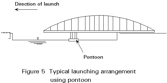
Whilst simple in principle, launching requires a site where large pieces of the bridge can be constructed in line with the final position but on the shore. The operation also requires very careful control and detailed analysis since, at various stages, bridge sections may be subjected to loadings differing greatly from those in service.
This method involves lifting a self-supporting part or the whole of a bridge into or near to its final position (Figure 6). Pieces lifted can vary from a small footbridge weighing a few tonnes, to a large section of a major crossing weighing over 1000 tonnes. Lifting may be a complete operation in itself, or part of a cantilever erection scheme.
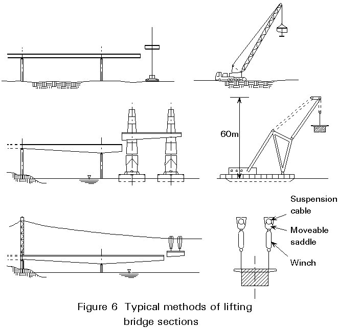
Lifting plant may range from small cranes for minor bridges, to very large floating cranes for major parts of estuarial bridges; alternatively winches or jacks on the already erected part of the bridge may be used. Hence the position and topography of the site will have a significant effect on the conceptual choice.
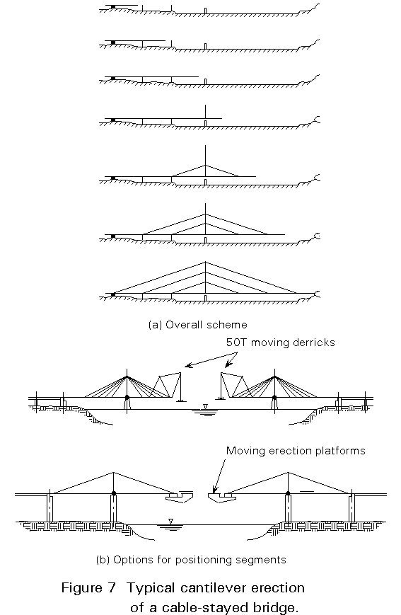
This method involves constructing a bridge, normally continuous over several spans, progressively from one or both abutments, by attaching sections to the end of already erected portions (Figure 7). An anchor span is lifted or assembled in situ, and sections then cantilevered from this by either lifting from ground level, or running along the deck and lowering from the end. The position of the site and the access to it will determine the size of the pieces erected and this in turn will have a bearing on the original choice of the structural concept. Cantilevering is an ideal method for erecting cable-stayed bridges, using the stays as supports for the cantilever as work progresses.
This method involves building the bridge offset laterally from the final site and then jacking and winching it sideways into its final position. It is typically used for replacing an existing bridge which cannot be taken out of service for a long period. For obvious reasons it is only possible to use it for a very strictly limited type of site.
It should go without saying that a bridge should be suited to local technology. It is not sensible to specify a sophisticated design in welded high tensile steel if all the material and labour has to be imported. This consideration applies not only to minor bridges - the new 460 m span Hooghly Bridge in Calcutta, under construction in 1992, was designed as a rivetted cable stayed bridge; rivetting skills were still available in India and local steels could have given problems with site welding; the design proved an economic solution whereas in Europe there are probably no riveters still in existence and weldable steel is the norm.
The importance of future inspection and maintenance cannot be overemphasised, both at the conceptual design and the detailed design stages. There is little doubt that too little attention has been given to it in the past, with the result that many bridges, otherwise satisfactory, have deteriorated because of difficulty in inspection and maintenance. It is particularly important that in locations where access is difficult (either physically or because it would cause disruption of services) details which deteriorate should be avoided as far as possible. This will be considered further in various respects, for example whether a bridge should be a series of simple spans or should be continuous.
At the conceptual design stage, a designer should consider whether it would be appropriate to use a material such as weather resistant steel or perhaps whether the structure should be fully enclosed with a non-maintenance material to protect it and give access for inspection. Either of these expedients could result, for example, in a requirement for greater clearance of the bridge above the obstacle being crossed. They might have to be considered together with the layout of the overall scheme. For example, the topography might show that a minor change of alignment could accommodate the greater clearance at little or no extra expense.
The appearance of bridges has in recent years become a matter of considerable importance. Frequently, a scheme takes a road or railway through an area of great natural beauty and it is important that any structures are in keeping with these surroundings and do not adversely affect them. Many authorities consider that there are some bridges which actually contribute to the environment by giving an interesting focus to an otherwise empty scene; the Severn Bridge is a typical example. Regrettably, however, there are many bridges for which the contrary is true. Not infrequently, the problem could have been avoided by following some simple rules.
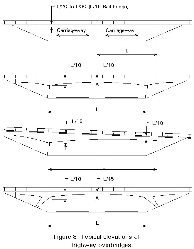
For example, it is commonly accepted that a bridge is more aesthetically pleasing with an odd number of spans than an even number. In addition, a degree of deepening at piers can add to the attraction. Figure 8 shows a typical location for a highway overbridge, with a number of possible solutions, any of which is normally structurally viable. There is little doubt that the 3-span structures are more attractive than the two span ones. Hence, unless there are other contra-indications, the conceptual choice should probably tend towards a 3-span solution.
In Section 3.3 it was pointed out that on a railway bridge, it is possible to mount the rails directly on the main girders. Unfortunately this arrangement gives rise to a high level of noise emission and so would not normally be acceptable, particularly in an urban area. Provision of a concrete deck slab together with the use of ballast and possibly elastomeric rail mountings can produce a dramatic improvement and shows where an "obvious" choice can be modified by environmental considerations.
In Sections 3 and 4 consideration was given to a number of general aspects which have to be taken into account by a designer in making a conceptual choice. In the current section, attention will be focused on some more detailed matters as an introduction to the particular forms of construction which are covered in other lectures. As the large majority of bridges are the simple girder type, attention will be concentrated on these.
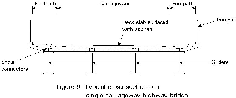
A typical cross-section of a short span highway bridge is shown in Figure 9. For obvious reasons such a bridge requires a deck on which the traffic can run. The deck must be strong enough to distribute the local loads to the main girders. For such multi-girder structures there is little conceptual choice for a designer - it has been found by experience that a reinforced concrete slab between about 200 and 300mm thick, supported at about 3 - 3,5m centres is suitable for most purposes. For large span structures, twin girder solutions become more attractive and either a thicker deck, probably with varying depth, is required or cross girders have to be introduced. Only in bridges where weight is at a real premium (e.g. long span bridges, or moving bridges) is it normally necessary to think further than this.
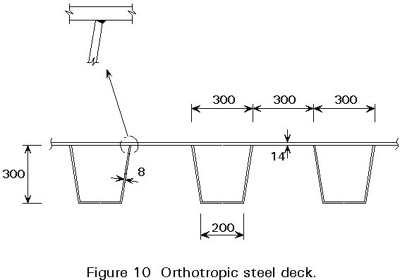
One possibility for reducing the deck weight is the use of lightweight concrete (an example is the 174m main span Friarton Bridge in UK where the deck has been constructed as a lightweight reinforced concrete slab). However, a more normal alternative to an RC slab is an orthotropically stiffened steel plate deck. Many layouts have been tried, some of which have suffered from premature fatigue from the repeated stresses from traffic. There now seems to be general agreement within Europe that the cross-section shown in Figure 10 is the "state of the art" solution for a steel deck in 1992.
Finally, it must be emphasised that in modern designs the deck, whether of reinforced concrete or stiffened steel plating, will invariably be connected to the girders below it so that it acts compositely with them in carrying the bending moments imposed on them. In the case of concrete decks this connection will be made using shear connectors (see Figure 9) and in the case of steel decks by a direct connection (normally welding or high strength friction grip bolting).
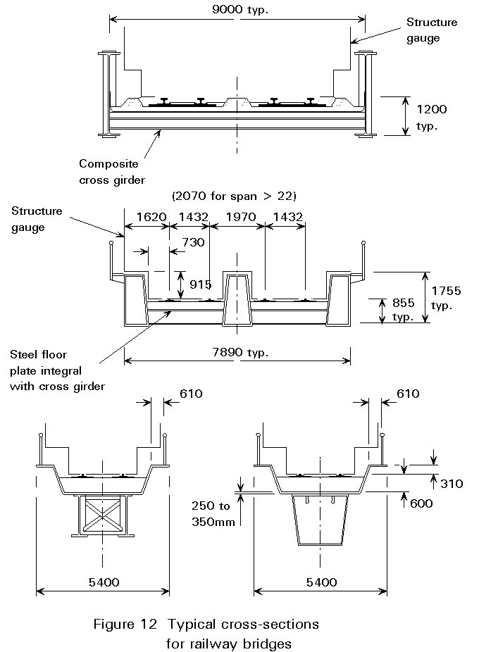
Figure 8 and figures 11 - 12 show a number of typical layouts for bridges of this type with indications of dimensions. Comment has already been made in Section 4.5 on the aesthetic aspects. In the present section some technical questions regarding the alternatives are addressed. For example:
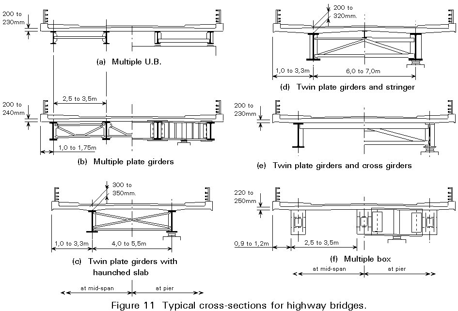
The bridges shown on Figures 5, 8, 11 and 12 are all real structures; Figure 11, in particular, identifies six types of cross-section for highway bridges, all of which have been used successfully. In the end, the test at the detailed design stage is which layout is the most economic for a particular site. To resolve this question may require a significant amount of trial and error calculation. It is useful, however, to lay down a few guidelines at the conceptual design stage (not necessarily in the same order as the questions above!):
|
For
|
Against
|
|
Items difficult to maintain, such as expansion joints, can be minimised. |
Compression in bottom flange near piers; hence potential stability problems. |
|
Advantages of reduced depth of construction |
Composite sections much more efficient in sagging than in hogging. |
|
May be essential for bridge erection and/or launching. |
Hyperstatic structure - indeterminate - problems with differential settlement, concrete shrinkage and temperature gradient. |
|
The reduction in maximum moments during concrete placing is useful. |
Whilst other forms of construction, e.g. cable stayed, have been used for short span bridges in the past, they are normally adopted only in cases where special conditions govern (e.g. moving bridges, severe restrictions on headroom, etc.) or where the undeniable aesthetic attraction of such bridges is an important consideration. Footbridges frequently fall into the latter category.
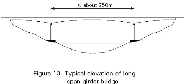
Long span girder bridges are normally developments of the plate or box girder forms described in the previous section. They will usually be continuous over two or more spans and will frequently be haunched. Normally the span limit is about 250 metres clear (although longer examples exist, e.g. Rio Niteroi). A typical elevation of such a girder bridge is shown in Figure 13.
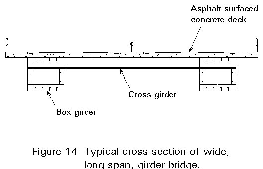
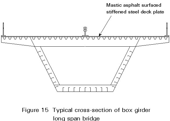
As with shorter spans, consideration has to be given to the cross-section (number of main girders, etc.) and the form of deck - normal reinforced concrete, lightweight reinforced concrete, orthotropically stiffened steel plate, etc. A very typical cross-section is the twin box girder with transverse girders as shown in Figure 14, although when the carriageway is comparatively narrow a single large box girder, frequently with an orthotropic steel deck, is quite common (Figure 15).
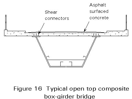
A form of construction used frequently in the USA and Canada, although not common in Europe, is the "open-top" composite box girder in which the reinforced concrete slab, placed in-situ, forms the complete top flange (Figure 16). The main problem with this form occurs during construction, when the tops of the webs need stabilising until the slab is placed.
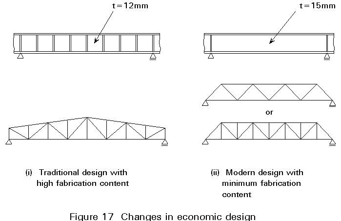
Any modern bridge designer must recognise that the ratio of material to labour costs has changed considerably within the last few decades. Depending on local conditions, 1 man hour now costs the same as 30 to 70kg steel. In the past, material costs were relatively greater and detailed designs close to practical minimum weight were also likely to be minimum cost designs.
In current conditions, it is frequently the case that the most economic design is one where the labour content of the fabrication has been minimised by careful design, where necessary at the expense of material weight. Figure 17 shows two examples where modern economic design is considerably simpler than earlier detailed designs. In the plate girder example shown, the stiffened girder would be 230kg lighter if it was 10m long but the seven stiffeners would each take at least ¾ hour to position and weld, a total time of 5¼ hours. Thus the heavier girder is cheaper in all fabrication shops where a man hour costs more than 230 ¸ 5¼ = 44kg of steel.
Design for minimum fabrication can influence directly the choice of structural form. Table 1 indicates the contributions to total cost of these different types of bridge girder, taking the total cost of a plate girder construction as 100 units.
|
Bridge Type |
Rolled Section |
Plate Girder |
Box Girder |
|
Steel |
30 |
30 |
30 |
|
Fabrication |
30 |
30 |
70 |
|
Corrosion Protection |
10 |
10 |
15 |
|
Erection |
10 |
10 |
15 |
|
TOTAL |
80 |
100 |
130 |
The influence of fabrication content is readily seen. Clearly a rolled section bridge can still be the cheapest solution even if it is significantly heavier than a box girder alternative.
The detailed economic comparison will vary considerably with local conditions but local fabricators will generally be only too ready to advise on the relative economics of different forms of construction.
Fabrication can be considerably facilitated by detailing which maximises repetition and also makes the bridge easier to construct. For example, incorporation of bolted joints for some connections introduces a tolerance to the structure which is not available in all-welded construction. Carefully positioned, they may minimise the use of expensive full penetration butt welds and may also reduce the risk of lamellar tearing. (The latter may require special treatment in welded construction with cruciform joints, such as the specification of material with guaranteed through thickness properties.) Once again, fabricators are usually pleased to advise designers on such matters.
Initial conceptual choice should take account of:
× clearance requirements and the avoidance of impact damage
× type of loading
× topography and geology of the site
× possible erection methods
× local skills and materials
× future inspection and maintenance
× aesthetic and environmental aspects
× deck structure
× layout i.e. spans and structural arrangements
× continuous or simple construction
× proportions, i.e. span/depth ratios
× reducing fabrication labour to a minimum
× design for ease of construction