ESDEP WG 8
PLATES AND SHELLS
To introduce methods of global analysis, methods of determining cross-section distortion, and shear lag in box girder bridges.
None.
Lecture 8.5.1: Introduction to Design of Box Girders
Global analysis may be made by the grillage, orthotropic plate, folded plate and finite element methods.
Distortion of the box may have to be controlled by diaphragms or cross frames. Simple or refined methods are available for the calculation of the forces in the diaphragms or cross frames.
In very wide flanges, shear lag effects have to be taken into account.
Although steel or steel-concrete composite box girders are usually more expensive per tonne than plate girders, because they require more fabrication time, they can lead to a more economic solution overall.
For bridges, box girders have several advantages over plate girders which make their use attractive:
Box girders are sometimes used in building structures, but this is not common. This lecture deals mainly with box girders as used in bridges, both all-steel construction and composite construction with a reinforced concrete deck slab; most of the general remarks are applicable to box girders used in buildings
Global analysis determines the load effects, bending moments, shear forces, torsional moments, etc., which occur in all parts of the structure as a result of the applied load. From this analysis stresses are determined, for comparison with the calculated strengths.
Methods of analysis for composite bridge decks fall into one of three groups.
Those in the first group are the simplest to analyse, since beam theory can be used for the behaviour of the individual elements. For a single straight girder a line-beam analysis can be used, provided this takes account of torsional effects as well as bending effects, but in general a grillage model is needed. Such an analysis gives good results for the distribution of moments and forces in multiple girder structures and when a curved single beam is modelled as a series of straight elements. However, simple beam theory does not take account of the distortion of the cross section or of shear lag effects and these must be determined separately.
Analysis in the second group is by use of finite element techniques and inevitably involves the use of a powerful computer program. Provided suitable elements are available within the computer program, the analysis is able to give results which include most of the structural effects, including distortion and shear lag, but choice of element type and size requires much experience, and interpretation of the results also requires careful consideration.
The third group applies more exact theoretical modelling techniques. Examples are treatment of the whole deck as an orthotropic plate and analysis of folded plate models. However such techniques can only be properly applied when there is uniformity throughout the structure and for distributed loading. They are also only able to represent separately some aspects of the behaviour: the loading therefore needs to be divided into components such as uniform bending, uniform torsional, warping torsion, and distortion.
In a grillage analysis, the structure is idealised as a number of longitudinal and transverse beam elements in a single horizontal plane, rigidly interconnected at nodes. Transverse beams may be orthogonal or skewed with respect to the longitudinal beams, so that skew, curved, tapering or irregular decks can be analysed.
In a simple grillage analysis, each beam is allotted a flexural stiffness in the vertical plane and a torsional stiffness. Vertical loads are applied only at the nodes. Computer software is used to carry out a matrix stiffness analysis to determine the displacements (rotations about the two horizontal axes and the vertical displacement) at each node and the forces (bending moments, torsional moments and vertical shear forces) in the beams connected to each node.
Grillage analysis does not determine warping and distortional effects, nor the effects of shear lag. Local effects under point loads (wheel loads) can only be studied with a grillage by the use of a fine mesh of beams locally to the load; local effects are usually determined separately and added to global results as required.
The global structural action of a box girder bridge can be seen as the essentially separate actions of a reinforced concrete slab (or an ortotropically stiffened steel deck) which bends transversely and a series of longitudinal beams which deflect vertically and twist. The slab (or steel deck) bends as a result of being supported along several lines which deflect by different amounts and in a manner which varies along the span. The global analysis therefore needs to model accurately the way in which these support lines deflect, so that the interaction between longitudinal and transverse bending is properly established.
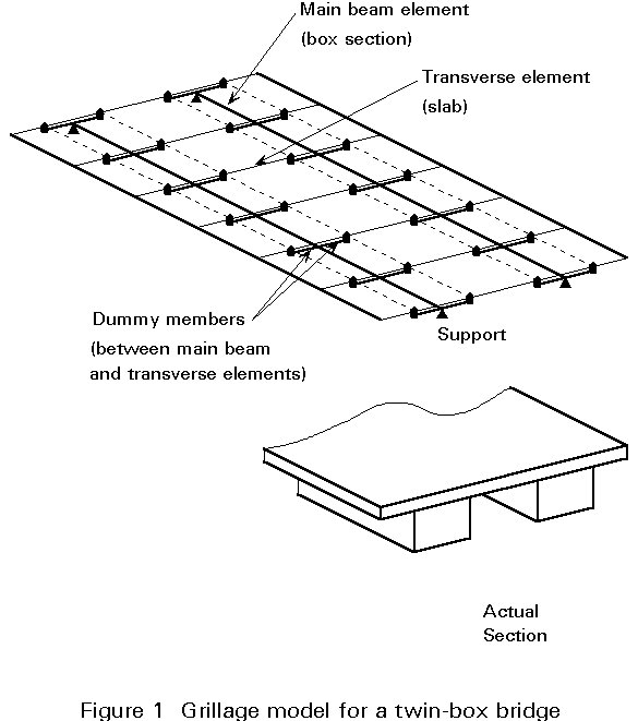
The slab is effectively supported along each web line. The vertical deflection of each web line depends on a combination of the vertical and torsional deflections of the box girder of which it is a part. The best way to model these effects is to create a torsionally stiff beam element along the centreline of each box (i.e. the shear centre) and to connect it to the slab at the web positions. To do this, short 'dummy' transverse beams are needed; they do not physically represent any particular part of the structure and the forces in them do not need to be analyzed, but they must be given sufficient stiffness that their bending is insignificantly small. This form of model for a twin-box bridge with cantilevers is illustrated in Figure 1 (note that, for clarity, the dummy beams and longitudinal beams are shown slightly below the slab, whilst they would actually be treated in the analysis as co-planar).

The main longitudinal beams are assigned the flexural properties of the full section of each girder (including the slab or deck). In multi-girder structures it is usual to consider the slab to be divided midway between boxes and for the full width of the cantilever to be included with the outer box. Strictly this is not exact, since it would introduce a discontinuity in the level of the neutral axis, but the inaccuracy is negligible.
The longitudinal elements representing the slab (shown dotted in Figure 1) are not strictly necessary, as they are much more flexible than the main girders, though they may be helpful in the application of distributed loads. They are shown here to illustrate the division of the slab.
The longitudinal edge elements may be added to represent the edge beam. They do not have a major effect on overall performance but are often helpful in the application of load on the cantilevers.
Where there are no transverse beams, the transverse elements simply represent a width of slab equal to the node spacing. Where there are transverse beams, including cross-beams and diaphragms inside the box, the elements should represent the stiffness of the effective transverse member.
The slab elements are supported only on the dummy elements, they are not connected directly to the longitudinal beams. There is no moment continuity between slab elements and the dummy beams.
For an open box section, the torsional stiffness K is given by the general expression:

Where A is the area of the box and t is the thickness of element ds.
When the section is composite, the concrete slab should be transformed into an equivalent thickness of steel by dividing by the modular ratio.
For a strip of solid slab the torsional stiffness is given by:
![]()
Where t is the thickness and b is the width of the strip.
However, in the grillage model only half this stiffness should be assigned to the transverse elements, since no Saint Venant shear stress flux goes around the perimeter of the strip's cross-section. Similarly, for an orthotropic steel deck, only the value H should be used for the torsional rigidity, not 2H.
Skewed arrangements of multiple boxes can be devised, provided that support diaphragms can remain essentially square to the box centrelines and that there are either no cross-girders between boxes or the cross-girders are square to the boxes. Similarly, grillage analysis with skew cross-members is difficult to interpret and gives uncertain results for all except small skews.
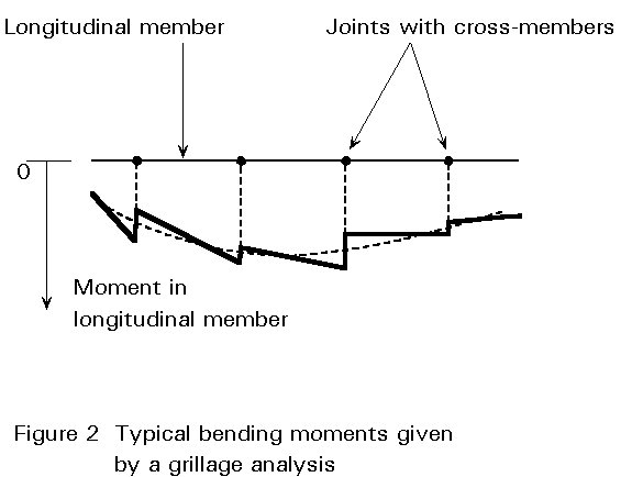
Computer software usually gives values of the vertical shear, bending moments and torsional moment for each grillage member at each joint in the grillage. Because the continuous structure has been idealised into discrete elements this discontinuity is unreal. A slightly 'better' value of moments in the main longitudinal members can be obtained by smoothing, as shown in Figure 2, though the difference is usually very small.
In orthotropic plate analysis, the deck structure is 'smoothed' across its length and breadth and treated as a continuum.
The elastic properties of an orthotropic plate are defined by the two flexural rigidities Dx and Dy and a plate torsional rigidity H. The governing equation relating deflection w to load P acting normal to the plane of the plate is:
![]() = p(x, y)
= p(x, y)
Design charts for decks that can be idealised as orthotropic plates have been derived from series solutions. They give deflections and longitudinal and transverse moments due to a point load, and so provide a rapid method for distribution analysis. Their applicability is limited to simply supported decks of skew not exceeding 20° whose elastic properties can be represented solely by length, breadth, and the three quantities Dx, Dy and H.
In composite structures, they can be used for beam-and-slab decks with not less than five equally spaced longitudinal members of uniform diaphragms over the supports.
The finite element method is used increasingly in civil engineering. It is the most versatile of the matrix stiffness methods of elastic analysis, and can, in principle, approach the solution of almost any problem of global analysis of a bridge deck.
In box girders, the finite element method allows the study of shear lag and the computation of effective flange breadths. It can also analyse local effects in slabs. To do this the webs, flanges and diaphragms are each divided into a suitable mesh of elements; the detail of the effects which can be revealed (for example the variation in stress across a flange due to shear lag) depends on the fineness of the mesh and the capabilities of the element types provided by the program.
The disadvantage of finite element analysis is its cost, especially because of the high level of expert time required for the idealisation of the structure. The expert's know-how is needed in selecting an appropriate pattern of elements, in selecting the right type of element and in determining the right limit conditions for boundary nodes along the supports. The interpretation of results also requires experience. The choice of inappropriate elements can be misleading in regions of steep stress gradient, because the conditions of static equilibrium are not then necessarily satisfied. The selection of the discretisation density level, or of the material behaviour, may have serious repercussions on the accuracy of the results.
Nevertheless, for complex situations, or for complex portions of a major structure, there is no better substitute for a finite element analysis.
The folded plate method is normally limited to assemblages of rectangular plates. It is not applicable to skew decks due to coupling between the harmonics. The orthotropic plates may extend over several spans but must be simply-supported at the extreme ends, with rigid diaphragms over the end supports. When folded plate diaphragms are used to represent the transverse frames, the advantages are that it can give a complete and accurate solution in less computer time than is needed for the finite element method, and it can accept a wide variety of types of loading and both displacement and force boundary conditions.
To apply the method to a double cellular box-girder bridge with one single internal web, the distortion must be divided into symmetric and asymmetric deformations. For boxes with more internal webs, it is possible to divide the deformations of the cross-section into eigenvalue functions of deformation.
Pure torsion of a thin walled section will also produce a warping of the cross-section, unless there is sufficient symmetry in the section. To illustrate how warping can occur, consider what would happen to the four panels of a rectangular box section subject to torsion.
Assume that the box width and depth are B and D respectively, and that the flange and web thicknesses are tf and tw. Under a torque T, the shear flow is given by q=T/2BD.
Consider first the flanges. The shear stress in the flanges is given by tf = q/tf =T/2BDtf. Viewing the box from above, each flange is sheared into a parallelogram, with a shear angle f =tf/G; if the end sections were to remain plane, the relative horizontal displacement between top and bottom corners would be fL at each end (see Figure 3a), and thus there would be a twist between the two ends of 2fL/D = 2tf L/DG = TL/BD2Gtf.
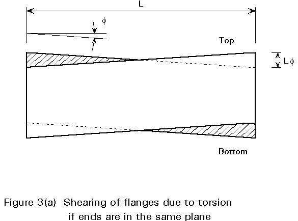
By a similar argument, viewing the box from the side and considering the shear displacements of the webs, if the end sections were to remain plane the twist of the section would be TL/B2DGtw. As the twist must be the same irrespective of whether we consider the flanges or the webs, it is clear that the end sections can only remain plane if TL/BD2Gtf = TL/B2DGtw, i.e. Dtf = Btw. If this condition is not met, the end sections cannot remain plane; instead there will be a slight counter-rotation in their planes of the two flanges and of the two webs, and a consequent warping of the section. Typical warping for this example is shown in Figure 3b.
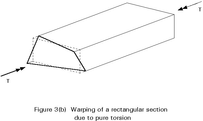
Of course, for a simple uniform box section subject to pure torsion this warping is unrestrained and does not give rise to any secondary stresses. But if, for example, a box is supported and torsionally restrained at both ends and then subjected to applied torque in the middle, warping is fully restrained in the middle by virtue of symmetry and torsional warping stresses are generated. Similar restraint occurs in continuous box sections which are torsionally restrained at intermediate supports.
This restraint of warping gives rise to longitudinal warping stresses and associated shear stresses in the same manner as bending effects in each wall of the box. The shear stresses effectively modify slightly the uniformity of the shear stress calculated by pure torsion theory, usually reducing the stress near corners and increasing it in mid-panel. Because maximum combined effects usually occur at the corners, it is conservative to ignore the warping shear stresses and use the simple uniform distribution. The longitudinal effects are, on the other hand greatest at the corners. They need to be taken into account when considering the occurrence of yield stresses in service and the stress range under fatigue loading. But since the longitudinal stresses do not actually participate in the carrying of the torsion, the occurrence of yield at the corners and the consequent relief of some or all of these warping stresses would not reduce the torsional resistance. In simple terms, a little plastic redistribution can be accepted at the ultimate limit state (ULS) and therefore there is no need to include torsional warping stresses in the ULS checks.
When torsion is applied directly around the perimeter of a box section, by forces exactly equal to the shear flow in each of the sides of the box, there is no tendency for the cross section to change its shape.
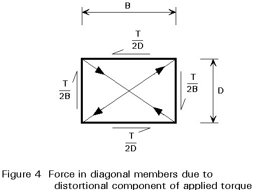
If torsion is not applied in this manner, there is effectively a set of forces which is trying to extend the length of one diagonal across the section and reduce the other (see Figure 4). Diaphragms or frames can be provided to restrain distortion where large distortional forces occur, such as at support positions, and at intervals along a box, but in general the distortional effects must be carried by other means.
To illustrate how distortion occurs and is carried between effective restraints, consider a simply supported box with diaphragms only at the supports and which is subject to a point load over one web at midspan. Under the distortional forces, each side of the box bends in its own plane and, provided there is moment continuity around the corners, out of its plane as well. The deflected shape is shown in Figure 5.
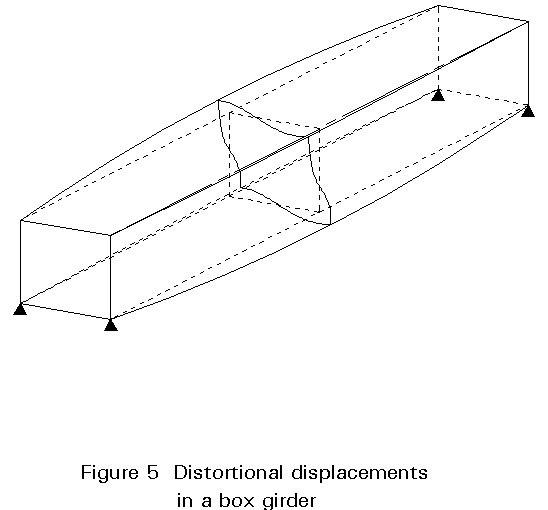
The in-plane bending of each side gives rise to longitudinal stresses and strains which, because they are in the opposite sense in the opposing faces of the box, produce a warping of the cross section (in the example shown the end diaphragms warp out of their planes, whilst the central plane can be seen to be restrained against warping by symmetry). The longitudinal stresses are therefore known as distortional warping stresses. The associated shear stresses are known simply as distortional shear stresses.
The bending of the walls of a box, as a result of the distortional forces, produces transverse distortional bending stresses in the box section.
The introduction of stiff intermediate cross-frames will restrict distortional effects to the lengths between frames (rather than between supports). but they must be stiff enough for this purpose.
In general the distortional behaviour depends on interaction between the two sorts of behaviour, the warping and the transverse distortional bending. The behaviour has been demonstrated to be analogous to that of a beam on an elastic foundation (BEF), with the beam stiffness representing the warping resistance and the elastic foundation representing the transverse distortional bending resistance. A comprehensive description of the analogy is given in a paper by Wright [1].
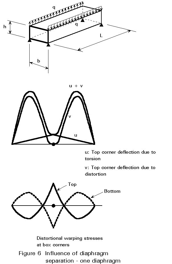
A diagrammatic illustration of the distortional behaviour of a box with a single intermediate diaphragm is given in Figure 6.
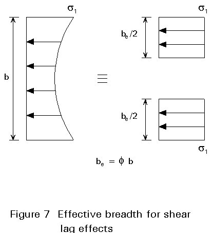
When the axial load is fed into a wide flange by shear from the webs the flange distorts in its plane; plane sections do not remain plane. The resulting stress distribution in the flange is not uniform In very wide flanges, shear lag effects have to be taken into account for the verification of stresses, especially for short spans, since it causes the longitudinal stress at a flange/web intersection to exceed the mean stress in the flange.
Shear lag can be allowed for in the elementary theory of bending, by using an effective flange breadth (less than the real breadth) such that the stress in the effective breadth equals the peak stress in the actual flange (see Figure 7). This effective flange breadth depends on the ratio of width to span.
For a simply supported beam, for example, the effective breadth of the portion between the webs is Fe.b , where Fe , the effective breadth ratio, is given in Table 1.
|
b/L |
Mid-span |
Quarter-span |
Support |
|||
|
a = 0 |
a = 1 |
a = 0 |
a = 1 |
a = 0 |
a = 1 |
|
|
0,00 0,05 0,10 0,20 0,30 0,40 0,50 0,75 1,00 |
1,00 0,98 0,95 0,81 0,66 0,50 0,38 0,22 0,16 |
1,00 0,97 0,89 0,67 0,47 0,35 0,28 0,17 0,12 |
1,00 0,98 0,93 0,77 0,61 0,46 0,36 0,20 0,15 |
1,00 0,96 0,86 0,62 0,44 0,32 0,25 0,16 0,11 |
1,00 0,84 0,70 0,52 0,40 0,32 0,27 0,17 0,12 |
1,00 0,77 0,60 0,38 0,28 0,22 0,18 0,12 0,09 |
Table 1: Effective breadth ratio Fe for simply supported beams
where
b is the distance between webs.
L is the span of the beam
a
=F
e is the elastic effective breadth ratio.Fortunately, in most situations the span/breadth ratio is not sufficiently large to cause more than 10-20% increase in peak stress, on account of shear lag.
At supports, forces are transferred from the box girder, through bearings, to the substructure below. Principally, these forces are vertical, though lateral restraint also has to be provided at certain selected positions. Where there is only a single bearing under the box and it offers little resistance to transverse rotation (e.g. elastomeric pot bearings), there will be no torsional restraint; the loads transferred from the two webs will be equal (presuming that the bearing is on the centreline). When there are two bearings, under or close to each of the webs, torsional restraint is provided to the box; the load from each web will be different, and there will be a transfer of torsional shear from the flanges. Whenever there is lateral restraint there will be an associated torque, because the restraint will not be at the level of the shear centre of the box.
The principal function of a support diaphragm is to provide an adequate load path to transfer shear forces from the webs to the bearings below the box. In doing so it also resists distortional forces.
Plated diaphragms are normally provided at supports, since they provide these functions most easily, although, strictly, an adequately braced cross-frame could also do so.
Clearly, full diaphragms close the box section, yet access into the box is necessary for completion of fabrication and for future inspection and maintenance. Openings are usually provided to permit access along the box, but the effect of these openings on the performance of the diaphragm has to be carefully considered; the size and position of any opening needs to be limited. This can be a particular problem with small boxes, because the minimum hole size may be a large proportion of the diaphragm size.
Diaphragms are usually provided with vertical stiffeners above the bearings because of the large forces involved, though with small boxes a thick unstiffened diaphragm may on occasion be appropriate.
A diaphragm behaves essentially as a deep beam, with the diaphragm plate acting as its web and an effective width of each of the box flanges acting as its top and bottom flange.
An example of an intermediate diaphragm in a large box girder of a cable stayed bridge is shown in Figure 8.
