ESDEP WG 8
PLATES AND SHELLS
To describe in a qualitative way the main characteristics of shell structures and to discuss briefly the typical problems, such as buckling, that are associated with them.
None.
Lecture 6.1: Concepts of Stable and Unstable Elastic Equilibrium
Lecture 8.1: Introduction to Plate Behaviour and Design
Lecture 8.4.1: Plate Girder Behaviour and Design I
Lecture 8.5.1: Design of Box Girders
Shell structures are very attractive light weight structures which are especially suited to building as well as industrial applications. The lecture presents a qualitative interpretation of their main advantages; it also discusses the difficulties frequently encountered with such structures, including their unusual buckling behaviour, and briefly outlines the practical design approach taken by the codes.
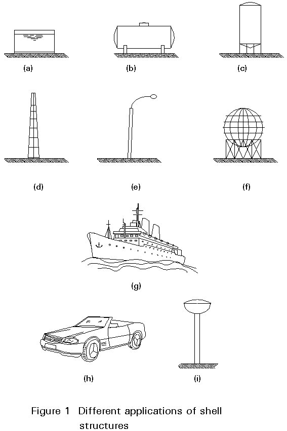
The shell structure is typically found in nature as well as in classical architecture [1]. Its efficiency is based on its curvature (single or double), which allows a multiplicity of alternative stress paths and gives the optimum form for transmission of many different load types. Various different types of steel shell structures have been used for industrial purposes; singly curved shells, for example, can be found in oil storage tanks, the central part of some pressure vessels, in storage structures such as silos, in industrial chimneys and even in small structures like lighting columns (Figures 1a to 1e). The single curvature allows a very simple construction process and is very efficient in resisting certain types of loads. In some cases, it is better to take advantage of double curvature. Double curved shells are used to build spherical gas reservoirs, roofs, vehicles, water towers and even hanging roofs (Figures 1f to 1i). An important part of the design is the load transmission to the foundations. It must be remembered that shells are very efficient in resisting distributed loads but are prone to difficulties with concentrated loads. Thus, in general, a continuous support is preferred. If it is not possible to have a foundation bed, as shown in Figure 1a, an intermediate structure such as a continuous ring (Figure 1f) can be used to distribute the concentrated loads at the vertical supports. On occasions, architectural reasons or practical considerations impose the use of discrete supports.
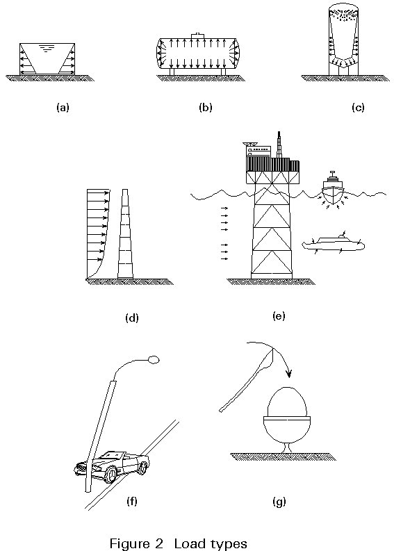
As mentioned above, distributed loads due to internal pressure in storage tanks, pressure vessels or silos (Figures 2a to 2c), or to external pressure from wind, marine currents and hydrostatic pressures (Figures 2d and 2e) are very well resisted by the in-plane behaviour of shells. On the other hand, concentrated loads introduce significant local bending stresses which have to be carefully considered in design. Such loads can be due to vessel supports or in some cases, due to abnormal impact loads (Figure 2f). In containment buildings of nuclear power plants, for example, codes of practice usually require the possibility of missile impact or even sometimes airplane crashes to be considered in the design. In these cases, the dynamic nature of the load increases the danger of concentrated effects. An everyday example of the difference between distributed and discrete loads is the manner in which a cooked egg is supported in the egg cup without problems and the way the shell is broken by the sudden impact of the spoon (Figure 2g). Needless to say, in a real problem both types of loads will have to be dealt with either in separate or combined states, with the conceptual differences in behaviour ever present in the designer's mind.
Shell structures often need to be strengthened in certain problem areas by local reinforcement. A possible location where reinforcement might be required is at the transition from one basic surface to another; for instance, the connections between the spherical ends in Figure 1b and the main cylindrical vessel; or the change from the cylinder to the cone of discharge in the silo in Figure 1c. In these cases, there is a discontinuity in the direction of the in-plane forces (Figure 3a) that usually needs some kind of reinforcement ring to reduce the concentrated bending moments that occur in that area.
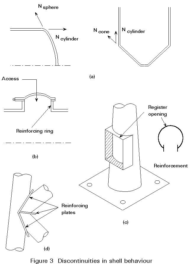
Containment structures also need perforations to allow the stored product (oil, cement, grain, etc.) to be put in, or extracted from, the deposit (Figure 3b). The same problem is found in lighting columns (Figure 3c), where it is general practice to put an opening in the lower part of the post in order to facilitate access to the electrical works. In these cases, special reinforcement has to be added to avoid local buckling and to minimise disturbance to the general distribution of stresses.
Local reinforcement is also often required at connections between shell structures, such as commonly occur in general piping work and in the offshore industry. In these cases additional reinforcing plates are used (Figure 3d), which help to resist the high stresses produced at the connections.
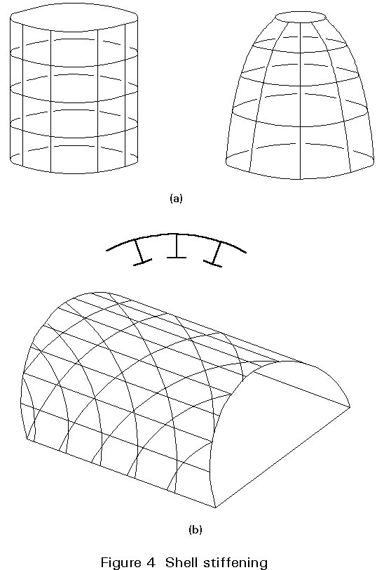
In contrast to local reinforcement, global reinforcement is generally used to improve the overall shell behaviour. Because of the efficient way in which these structures carry load, it is possible to reduce the wall thickness to relatively small values; the high value of the shell diameter to thickness ratios can, therefore, increase the possibility of unstable configurations. To improve the buckling resistance, the shell is usually reinforced with a set of stiffening members.
In axisymmetric shells, the obvious location for the stiffeners is along selected meridians and parallel lines, creating in this way a true mesh which reinforces the pure shell structure (Figure 4a). On other occasions, the longitudinal and ring stiffeners are replaced by a complicated lattice (Figure 4b), which gives an aesthetically pleasing structure as well as mechanical improvements to the global shell behaviour.
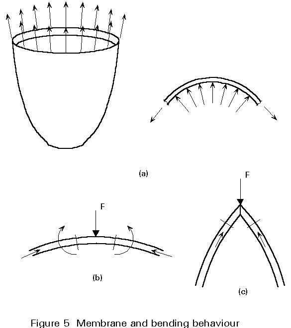
There are two main mechanisms by which a shell can support loads. On the one hand, the structure can react with only in-plane forces, in which case it is said to act as a membrane. This is a desirable situation, especially if the stress is tensile (Figure 5a), because the material can be used to its full strength. In practice, however, real structures have local areas where equilibrium or compatibility of displacements and deformations is not possible without introducing bending. Figure 5b, for instance, shows a load acting perpendicular to the shell which cannot be resisted by in-plane forces only, and which requires bending moments, induced by transverse deflections, to be set up for equilibrium. Figure 5c, however, shows that membrane forces only can be used to support a concentrated load if a corner is introduced in the shell.
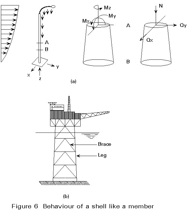
It is worthwhile also to distinguish between global and local behaviour, because sometimes the shell can be considered to act globally as a member. An obvious example is shown in Figure 6a, where a tubular lighting column is loaded by wind and self-weight. The length AB is subjected to axial and shear forces, as well as to bending and torsion, and the global behaviour can be approximated very accurately using the member model. The same applies in Figure 6b where an offshore jacket, under various loading conditions, can be modelled as a cantilever truss. In addition, for certain types of vault roofs where the support is acting at the ends, the behaviour under vertical loads is similar to that of a beam.
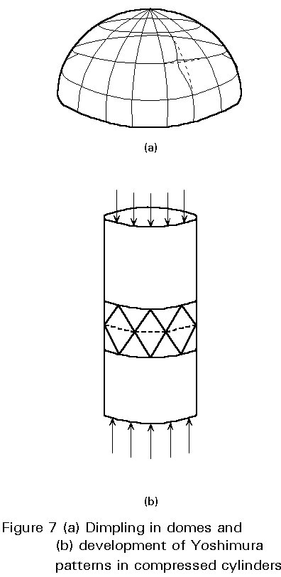
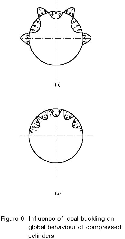
Local behaviour, however, is often critical in determining structural adequacy. Dimpling in domes (Figure 7a), or the development of the so-called Yoshimura patterns (Figure 7b) in compressed cylinders, are phenomena related to local buckling that introduce a new level of complexity into the study of shells. Non- linear behaviour, both from large displacements and from plastic material behaviour, has to be taken into account. Some extensions of the yield line theory can be used to analyse different possible modes of failure.
To draw a comparison with the behaviour of stiffened plates, it can be said that the global action of shell structures takes advantage of the load-diffusion capacity of the surface and the stiffeners help to avoid local buckling by subdividing the surface into cells, resulting in a lower span to thickness ratio. A longitudinally-stiffened cylinder, therefore, behaves like a system of struts-and-plates, in a way that is analagous to a stiffened plate. On the other hand, transverse stiffeners behave in a similar manner to the diaphragms in a box girder, i.e. they help to distribute the external loads and maintain the initial shape of the cross-section, thus avoiding distortions that could eventually lead to local instabilities. As in box girders, special precautions have to be taken in relation to the diaphragms transmitting bearing reactions; in shells the reaction transmission is done through saddles that produce a distributed load.
As was explained in previous lectures, the theoretical limits of bifurcation of equilibrium that can be reached using mathematical models are upper limits to the behaviour of actual structures; as soon as any initial displacement or shape imperfection is present, the curve is smoothed [2]. Figures 8a and 8b present the load-displacement relationship that is expected for a bar and a plate respectively; the dashed line OA represents the linear behaviour that suddenly changes at bifurcation point B (solid line). The plate has an enhanced stiffness due to the membrane effect. The dashed lines represent the behaviour when imperfections are included in the analysis.
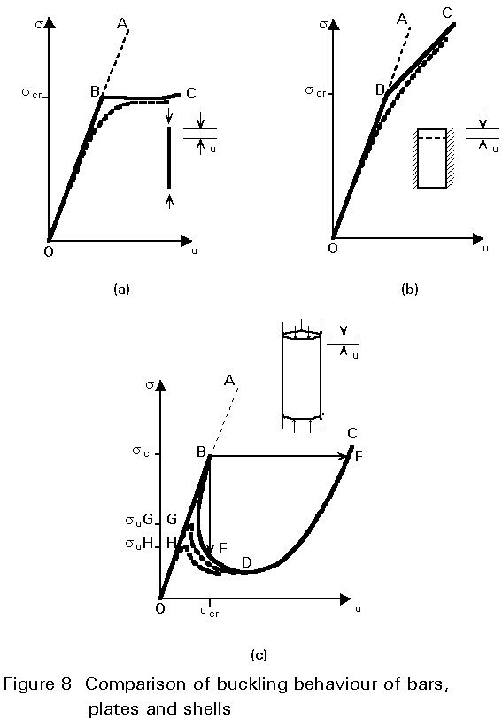
As can be seen in Figure 8c, the post-buckling behaviour of a cylinder is completely different. After bifurcation, the point representing the state of equilibrium can travel along the secondary path BDC. Following B, the situation is highly dependent on the characteristics of the test, i.e. whether it is force-controlled or displacement controlled. In the first case, after the buckling load is reached, a sudden change from point B to point F occurs (Figure 8c) which is called the snap-through phenomenon, in which the shell jumps suddenly between different buckling configurations.
The behaviour of an actual imperfect shell is represented by the dashed line. Compared with the theoretically perfect shell, it is evident that true bifurcation of equilibrium will not occur in the real structure, even though the dashed lines approach the solid line as the magnitude of the imperfection diminishes. The high peak B is very sharp and the limit point G or H (relevant to different values of the imperfection) refers to a more realistic lower load than the theoretical bifurcation load.
The difference in behaviour, compared with that of plates or bars, can be explained by examining the pattern of local buckling as the loading increases. Initially, buckling starts at local imperfections with the formation of outer and inner waves (Figure 9a); the latter represent a flattening rather than a change in direction of the original curvature and set up compressive membrane forces which, along with the tensile membrane forces set up by the outer waves, tend to resist the buckling effect. At the more advanced stages, as these outer waves increase in size, the curvature in these regions changes direction and becomes inward (Figure 9b). As a result, the compressive forces now precipitate buckling rather than resist it, thus explaining why equilibrium, at this stage, can only be maintained by reducing the axial load.
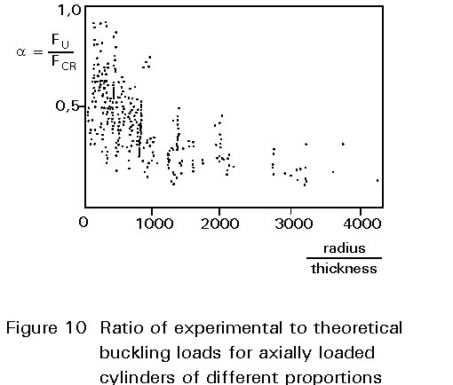
The importance of imperfections is such that, when tests on actual structures are carried out, the difference between theoretical and experimental values produces a wide scatter of results (see Figure 10). As the imperfections are unavoidable, and depend very much on the quality of construction, it is clear that only a broad experimental series of tests on physical models can help in establishing the least lower-bound that could be used for a practical application. Thus it is necessary to choose:
In consequence, the experimental results can only be used for a very narrow band of applications. In addition, the quality control on the finished work must be such that the experimental values can be used with confidence.
To allow for this, Codes of Practice [3] use the following procedure:
[1] Tossoji, Ei., "Philosophy of Structures", Holden Day 1960.
[2] Brush, D.O., Almroth, B.O., "Buckling of Bars, Plates and Shells", McGraw Hill, 1975.
[3] European Convention for Constructional Steelwork, "Buckling of Steel Shells", European Recommendation, ECCS, 1988.