ESDEP WG 15B
STRUCTURAL SYSTEMS: BRIDGES
To describe the main features of contemporary cable stayed bridges in steel and to present guidelines for their design and analysis.
None
Lecture 15B.1: Conceptual Choice
Lecture 15B.2: Actions on Bridges
Lecture 15B.3: Bridge Decks
Lecture 15B.4: Plate Girder and Beam Bridges
Lecture 15B.6: Box Girder Bridges
Lecture 15B.9: Suspension Bridges
The continuous development of the cable stayed bridge since the 1950's is described and the arrangement of the stay cables, the supporting conditions for the girder, the cable planes and type of girder are introduced. The choice of elements is discussed and special aspects of behaviour and analysis are described. The special connections required are also described and special features of construction are given.
Cable stayed bridges have been built for centuries but up to the 1950's they had not been developed to the same extent as other bridge types, such as truss bridges, arch bridges and suspension bridges.
However, since the completion of the Strömsund Bridge in 1955, the cable stayed bridge has been continuously developed. It has appeared in a larger number of variants than any other bridge type during this period.
The cable stayed bridge is mainly used for road bridges, where it is applicable for both narrow 2-lane roads and for wide 6 or 8 lane motorways.
Another application is within the field of pedestrian bridges where cable stayed bridges can prove advantageous also for smaller spans.
Finally, cable stayed bridges have been designed to carry railway lines, in a few cases.
The cable stayed bridge has been used for a span range from approximately 150m to 400m, where it has proved to be very competitive against truss bridges, arch bridges and box girder bridges. Recently, the cable stayed bridge has started to increase its span range up to almost 900m, i.e. moving into a span range that previously has been entirely in the domain of suspension bridges.
The impressive development of cable stayed bridges is reflected in Table 1 which shows the largest cable stayed bridges built from 1955 to 1993.
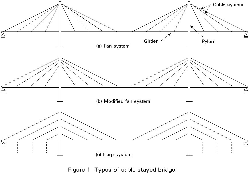
The cable stayed bridge consists of the bridge girder, the stay cables and the pylons (Figure 1).
For the system of stay cables, two main configurations are generally found: the fan system, Figure 1a, and the harp system Figure 1c.
The fan configuration leads to the most efficient structural system as it is entirely composed of triangles. In contrast, the harp system contains mainly quadrangles, and, therefore, an additional bending stiffness of the girder or the pylon is required to carry a non-uniform load.
In the pure fan system, all stay cables radiate from the pylon top as indicated for System (a). It will, however, in many cases be complicated to anchor all the cables at one point at the pylon top. To avoid this difficulty, the fan system is often modified so that the cable anchors at the pylon top are spread over a certain height, as shown for System (b).
Provided that the cable anchors are concentrated in a relatively narrow zone at the pylon top, there is no significant difference between the behaviour of bridges with the pure fan or with the modified fan.
The efficiency of the harp system can be significantly improved by adding intermediate supports in the side spans, as indicated by dotted lines in System (c) of Figure 1.
In modern cable stayed bridges, the cable system is generally of the multi-cable configuration where each stay consists of a mono-strand prefabricated in full length and full cross-section. To achieve this arrangement, it is necessary to have the stay cables closely spaced. The distance between the cable attachments at the girder is therefore often chosen between 10 and 20 m.
Cable stayed bridges are generally built as self-anchored systems where the supporting conditions are chosen so that vertical load from the self-weight and the traffic introduces vertical reactions only.
This loading can be achieved by supporting the stiffening girder on one fixed bearing and three longitudinally movable bearings, as indicated on Figure 2a for a system with the pylons fixed to the stiffening girder.
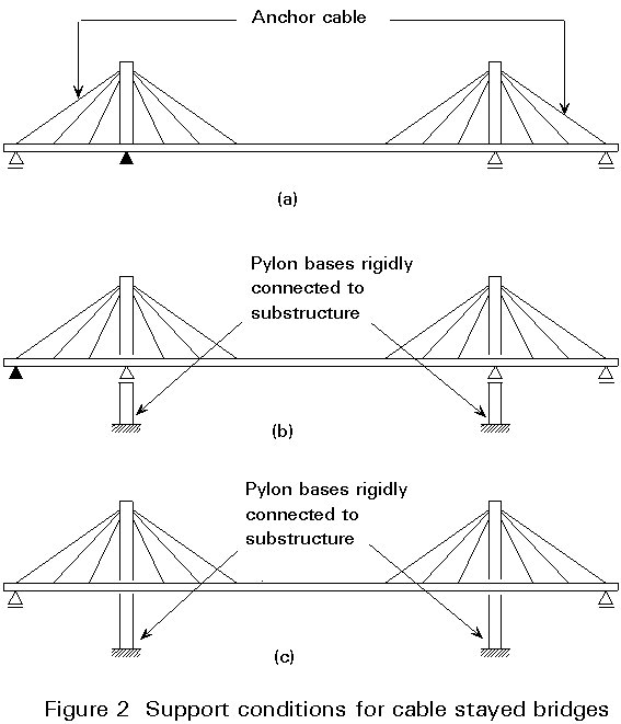
There are, however, many variants to this basic system and in some systems, horizontal reactions of moderate size might occur due to compatibility phenomena.
For example, Figure 2b shows a system with a fixed end bearing and pylons that are rigidly connected to the substructure.
For this system, the elongation of the left anchor cable will force the top of the left pylon to deflect in the longitudinal direction introducing bending and horizontal shear. In addition, the contraction of the girder, e.g. under traffic load, will result in a longitudinal displacement of the movable end bearing to the right and this displacement will partly be transmitted to the top of the right pylon by the right anchor cable.
It should also be noted that elongations or contractions of the girder due to temperature effects will introduce displacements of the pylon tops, and thereby horizontal shear in the pylon legs.
In some cable stayed bridges, the girder will have direct vertical supports only at the end piers whereas it will be free to move vertically at the pylons. With this system, a total symmetry under temperature variations can be achieved if both end bearings are longitudinally movable, as indicated on Figure 2c. With this system longitudinal forces, e.g. from braking, will have to be transferred to the soil by bending of the pylons. This system is, therefore, only applicable if the longitudinal forces are of moderate intensity.
In cross-section the cable system is generally arranged in one vertical plane above the centre line, in two vertical planes at the edges of the girder or in two inclined cable planes - as shown in Figure 3.
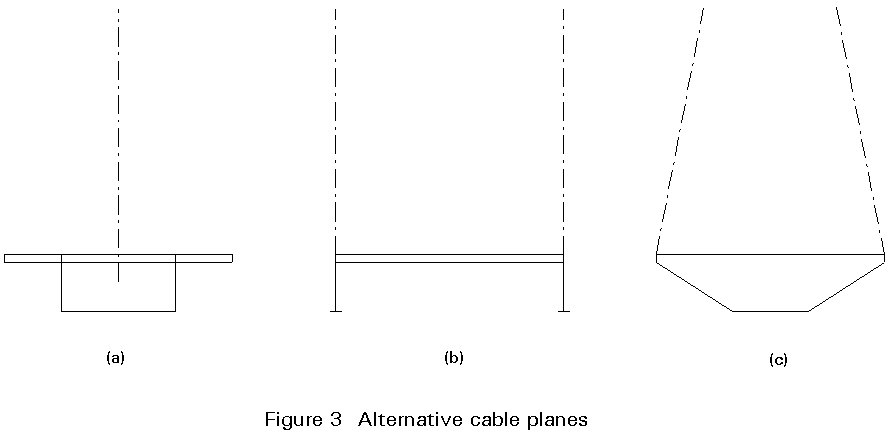
A central cable plane with the stay cables attached along the girder axis provide (elastic) vertical support to the girder, but no torsional support. It is, therefore, essential that the girder has a sufficient torsional stiffness to transmit any twisting moment from a load with an eccentric resultant, e.g. traffic load in only one carriageway.
To achieve the required torsional stiffness, the girder will have to be of the box type, Figure 3a.
With two vertical cable planes attached along the edges of the girder, both vertical and torsional support is provided by the cable system and it is therefore not required that the girder in itself possesses torsional stiffness.
The girder can simply consist of two I-shaped plate girders directly under the cable planes Figure 3b.
With two inclined cable planes intersecting at the top of the pylon, the girder in principle gets the same cable support as with two vertical cable planes. In this case a girder with torsional stiffness is also not required.
In cable stayed bridges with very long spans, where the torsional stiffness becomes essential to achieve aerodynamic stability, it is often advantageous to have a box girder combined with two cable planes, and also to give the girder a favourable streamlined shape, as illustrated in Figure 3c. It should, however, be emphasized that a lay-out such as that of Figure 3c is only required for very long spans (above 500m) or for small width-to-span ratios (below 1/25).
The main advantage of applying a cable support to bridges is linked to the fact that cable steel can be manufactured with a much higher strength than structural steel.
For cold drawn steel wires with a diameter of 5-7mm, an ultimate strength of 1600 MPa is easily achieved, whereas ordinary structural steel has ultimate strength of 350-500 MPa. In other words, cable steel is 3-4 times stronger than ordinary structural steel. This difference implies that an element under pure tension, if made of cable steel, will have a cross-section (and a weight) that is only 25-33% of that required with structural steel.
Each stay cable is composed of a large number of wires, either with a circular shape and diameters between 5 and 7mm or with a special shape to give a higher degree of compaction and a more dense surface.
In the so-called locked coil cable, Figure 4, the outer layers are composed of Z-shaped wires that fit tightly together, whereas the inner wire layers are cylindrical. All layers are helical with the direction of helix changing from one layer to the next.
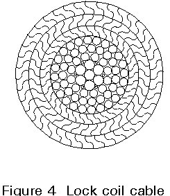
Due to the twisting of the wires, the locked coil cable becomes self-compacting, so that a wrapping is unnecessary. At the same time the interlocking Z-wires of the outer layers ensure a tight surface of the cable under tension, and the required corrosion resistance can therefore often be achieved just by galvanizing the wires.
In helical cables the axial stiffness is influenced by the twisting of the wires and the modulus of elasticity is therefore reduced by 15-25% to a typical value of 170 ´ 103 MPa.
The twisting of the wires also slightly influences the fatigue strength, so that the stress range endured by the cable is smaller than for the wires themselves.
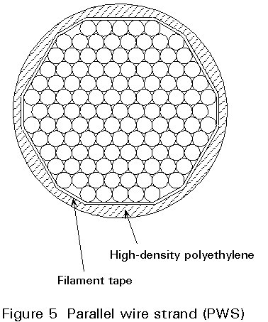
In the other type of stay cable, the parallel wire strand (PWS), the drawbacks of the helical strand are eliminated by having all wires parallel and straight (or twisted with a very long lay corresponding to a twist angle of less than 3°).
With parallel and straight wires the cable is without a self compacting effect. A special wrapping is, therefore, required to keep the wire bundle together and establish the necessary corrosion protection.
In the early cable stayed bridges with parallel wire strands (PWS), the wires were generally blank (ungalvanized) and the corrosion protection established by placing the wires inside a polyethylene tube that was injected with cement grout after installation of the stay cable.
In the more recent developments the PWS is composed of galvanized wires and the cement grout is substituted by a corrosion inhibiting compound or the tube is extruded directly onto the wire bundle, Figure 5.
In steel bridges, the girder is composed of stiffened steel panels, as illustrated for a box girder in Figure 6.
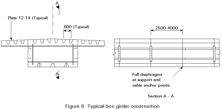
The deck plate is typically 12-14mm thick and stiffened by longitudinal ribs giving support along lines a distance of 300mm apart, i.e. with trapezoidal ribs each attached along two lines the distance between the centres of the ribs is 600mm.
The longitudinal ribs are supported by cross beams or diaphragms spaced 2,5-4m apart, and these transverse elements are finally attached to the main girder. Thus the transfer of concentrated wheel loads acting on the bridge deck to the main girder induces plate bending in the deck plate, and bending plus shear in both the longitudinal ribs and the cross beams or diaphragms. This results in a rather complicated biaxial stress distribution in the deck plate. To determine this distribution, the local structural system should be modelled as an orthogonal grid of beam elements.
The webs and the bottom plate of the box girder also have to be stiffened by longitudinal and transverse ribs. In this case the main purpose of the stiffeners is to prevent buckling - a phenomenon that is especially important to consider as the girder forms an important part of the primary structural system by transmitting in compression the horizontal components of the stay cable forces.
Full diaphragms, either plated or braced, are generally positioned at all cable anchor points and at the pylons, whereas the intermediate transverse elements can be composed of relatively shallow plate girders.
For a girder with an open cross-section and a concrete deck, an efficient structural system can be achieved by applying plate girders directly under the cable planes and interconnecting these main girders by transverse girders at intervals of 3-5m (Figure 7).
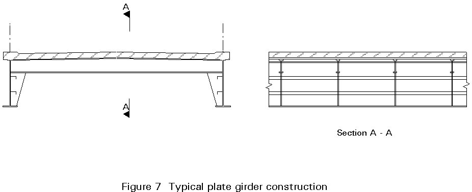
With this system, the transverse girders are subjected to positive moments over the entire length so that they can fully benefit from acting compositely with the concrete slab. Similarly the composite action is also favourable for the longitudinal girders, being subjected to compression by the horizontal components of the stay cable force.
Both the main girders and the transverse girders therefore, have shear studs on their top flanges.
The configuration of the pylon is closely related to the lay-out of the cable system, as the main function of the pylon is to support the stay cables.
In bridges with a central cable plane the pylon can be designed as a free standing column or as a lambda-shaped frame, as shown in Figure 8a.
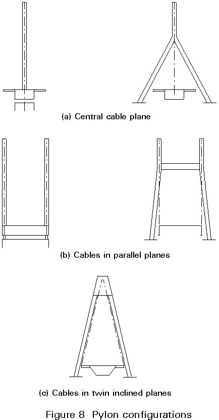
The free standing vertical pylon at the centre of the bridge deck is well suited to support both a harp-shaped and a fan-shaped cable system, whereas the lambda pylon requires a modified fan system.
The vertical pylon must have a rigid moment connection to either the box shaped main girder, or to the bridge pier, to be stable in the lateral direction.
The lambda pylon has in most cases its inclined legs passing outside the girder without a direct connection.
In bridges with two vertical cable planes, the pylon can either consist of two vertical columns or form a portal frame, as shown on Figure 8b. Regarding supporting conditions at the bottom and lay-out of the cable system, the double pylon under (b) closely corresponds to the matching single pylon under (a).
With two inclined cable planes, the pylon is A-shaped in most cases, Figure 8c, in combination with a modified fan system. Other combinations are theoretically possible.
The cross-section of the pylon generally forms a rectangular box with a single cell. Due to the dominating compression it is necessary to stiffen the side plates primarily with longitudinal stiffeners, as shown in Figure 9.
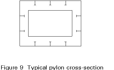
Transverse diaphragms are required to support the longitudinal stiffeners at certain intervals. Due to the fact that very little torsion is applied to the pylon, the diaphragms do not need to be very rigid. They can therefore be made with relatively large openings (man holes) to ease inspection and maintenance.
At the cable anchor zones, it may be necessary to add more robust horizontal diaphragms and/or vertical bulkheads to ensure the transmission of the stay cable forces to the pylon cross-section and to the stay cables in the opposite side.
For the design of the structural elements in a cable stayed bridge it is sufficient in most cases to use a standard two- or three-dimensional frame analysis program.
For bridges with only one, central cable plane, a two-dimensional structural system is adequate to analyse the structure under vertical loading due to dead load and traffic load. This analysis gives the forces in the stay cables, and the axial forces, shear forces and bending moments in the girder and the pylons.
For the torsion induced in the girder under one-sided traffic load, the girder can be analyzed subsequently without taking the cable system and the pylon into account. The same type of analysis applies to the girder under lateral load, e.g. wind load.
In bridges with two cable planes the mathematical model has to be three-dimensional.
For a bridge with two main girders, see Figure 3b, the mathematical model should be as indicated in Figure 10a, i.e. with two longitudinal beam elements to model the main girders and a large number of transverse beam elements to model the transverse girders. The stay cables can in most cases be modelled as straight bars carrying pure tension.
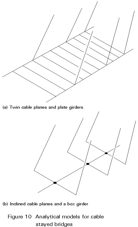
For bridges with a single box shaped girder and two cable planes, as illustrated in Figure 3a, the mathematical model should comprise a single longitudinal girder with the flexural and torsional stiffness of the box shaped main girder. At the points of cable attachment the central beam should be joined to transverse beam elements, as illustrated in Figure 10(b).
In the analysis, the stay cable is in most cases regarded as a straight member subjected to pure tension. In reality an inclined cable is always slightly curved due to the action of the cable's own weight.
For long stay cables, the sag, or rather the sag variations, tends to reduce the axial stiffness as the elongation is due not only to the elastic strains in the cable wires but also to a reduction of the sag, as illustrated in Figure 11.
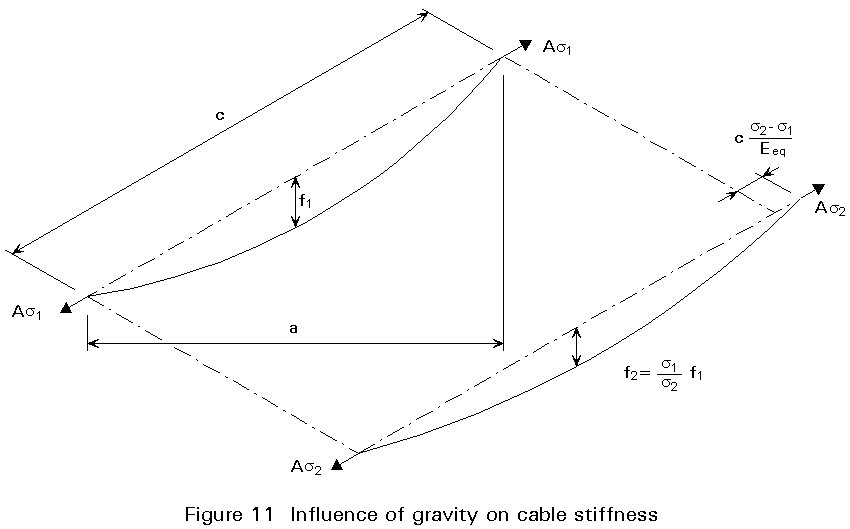
For stay cables with horizontal projections up to 150m and moderate stress variations, the sag effect can generally be disregarded, but for longer cables the stiffness of the cable support is overestimated if the axial strain is only considered.
The sag effect can be taken into account in the analysis by substituting the real modulus of elasticity E of the cable material by an equivalent modulus of elasticity Eeq determined by:
 (1)
(1)
where
g
is the density of the cable materiala the horizontal projection of the cable
s
1 is the initial dead load, stresss
2 the final stress (from dead + live load)Equation (1) which introduces a secant modulus, requires an iteration in the structural analysis, as the final stress s2 is unknown from the beginning.
For stay cables with moderate stress variations and horizontal projections up to 250-300m, it is allowable to substitute the secant modulus of Equation (1) by a tangent modulus Etan derived simply by inserting s2 = s1 in Equation (1):
 (2)
(2)
In this case an iteration can be avoided as the tangent modulus depends only on the initial stress s1.
When applying the more exact secant modulus approach, the first step in the iteration is often based on axial cable stiffnesses found from Equation (2), whereas the following steps are based on stiffnesses determined from Equation (1).
The pylon is subjected primarily to compression from the vertical components of the cable forces. For this reason it is very important to consider column buckling when designing the pylon.
It is, therefore, essential to determine thoroughly the effective length of the column to be applied in the actual case. To illustrate this feature, three examples are shown in Figure 12.
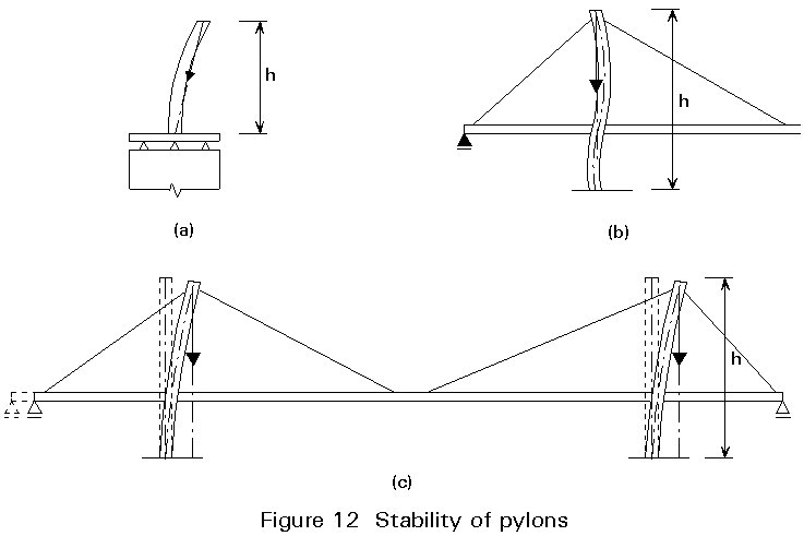
Figure 12a shows the lateral buckling of a free standing pylon supporting a pure fan system at the top. The column length 1c is equal to the pylon height h due to the fact that the cable plane rotates with the anchor point at the pylon top so that the resultant of the stay cable forces still points towards the bridge axis.
If this effect had been neglected, then the column length of the free standing pylon would have been stipulated at twice the pylon height, i.e. a much more severe condition.
Figure 12b shows the buckling of a pylon in the longitudinal direction in a system where the girder is longitudinally supported at the end pier. In this case the anchor cable leading from the fixed bearing to the pylon top restrains the pylon top in the longitudinal direction and the column effective length in the plane is therefore close to 0,7 times the pylon height.
Finally, Figure 12c shows the buckling of a pylon in a system where the girder has no longitudinal restraint through fixed bearings. In this case, the buckling is accompanied by a longitudinal sway of the girder so the cable reaction remains vertical. The column length is, consequently, twice the pylon height.
In cable stayed bridges, special connections are required to allow the transmission of the cable forces to the girder and the pylon.
Due to the fact that the high strength of the wires is achieved by a carbon content approximately five times larger than in normal structural steel, the wires cannot be welded.
Instead sockets are fixed to the ends of the wire bundle constituting the stay cable.
The sockets are made of cast steel in the form of a short cylinder with a conical cavity, Figure 13. Inside this cavity the strand is broomed and subsequently the space is filled with a metallic zinc alloy or a mixture of epoxy resin, zinc dust and steel balls.
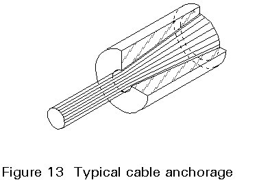
The transmission of the cable force from the socket to the adjacent structure is established as contact pressure on the end face or through an external thread to a nut. The socket might also have a shape that allows a pin connection.
During erection the length of the stay cables has to be adjusted either by inserting shims between the socket and the supporting structure or by turning the nut.
To vary the length of the stay cable, it is only necessary to make adjustments at one end (at the active anchorage). Thus the other end can be made without provision for adjustments (the passive anchorage).
The active anchorage can be positioned either at the girder or at the pylon. The choice between these two possibilities depends on the accessibility in the actual locations.
In modern cable stayed bridges with stay cables made of mono-strands it is generally a requirement that the stay cables can be replaced in the event of corrosion or fatigue leading to wire breaks. The anchorage detail should, therefore, also allow the stay cable to be released and removed in the service state.
When designing the cable anchor point at the girder, it is necessary to consider thoroughly the transmission of both the vertical and the horizontal component of the cable force.
Throughout the history of cable stayed bridges a very large number of anchorage details have been developed for the special conditions at the girder level.
As an example, Figure 14 shows a simple solution for anchoring a central cable to a box girder. Here the cable force is transferred from the socket through a bearing plate to two gusset plates welded to the deck plate and to a plated diaphragm. Thus, the horizontal component of the cable force is transferred to the deck plate by shear in the longitudinal weld and the vertical component to the diaphragm by shear in the vertical weld.
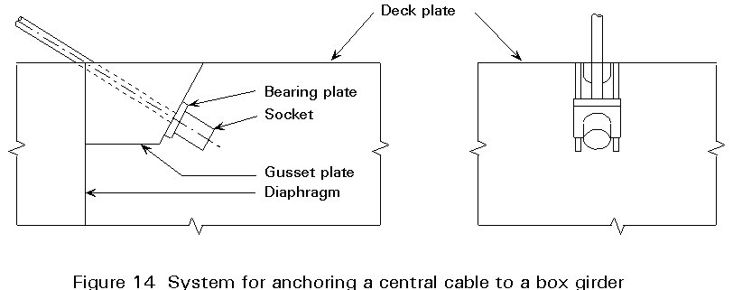
It is emphasized that the deck plate and the diaphragm must intersect exactly at the cable axis in order to exclude moments due to eccentricity.
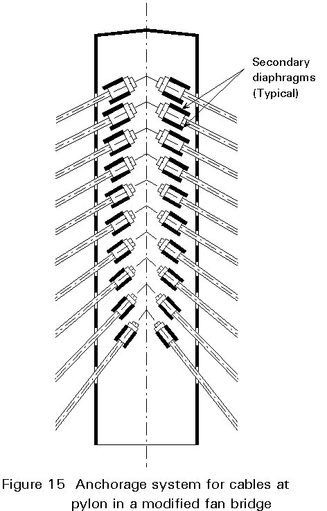
At the pylon, the stay cables might be anchored to inclined, secondary diaphragms extending between the two longitudinal side plates of the pylon, as illustrated in Figure 15 for a pylon supporting a modified fan.
The success of the cable stayed bridge is to a large extent linked to the efficient erection procedure which characterizes this type of bridge. Thus, a cable stayed bridge can be erected by free cantilevering from the pylon, either symmetrically in both directions (Figure 16a) or only into the main span (Figure 16b). In the latter case, the side span is erected initially as a normal girder bridge.
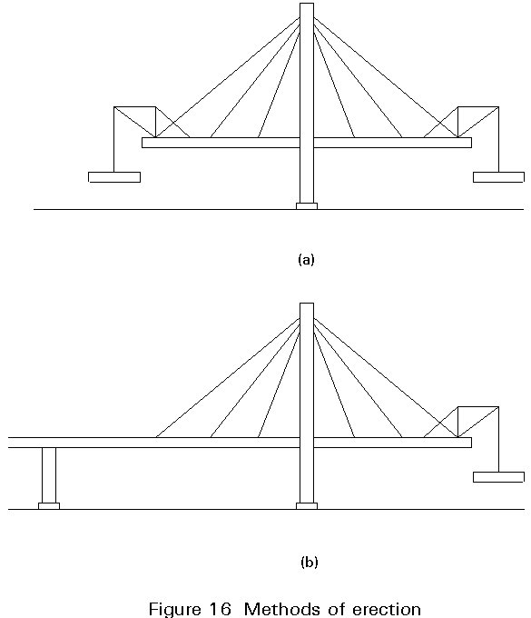
With the double cantilevering, Figure 16a, it must be remembered that the entire stability in the temporary stage depends on the flexural stiffness and the fixity of the pylon. In some cases this stiffness governs the design of the pylon.
With cantilevering only into the main span (Figure 16b) the stay cables are generally installed in pairs so that the fan (or harp) of the side span is established simultaneously with that of the main span.
Typically an erection sequence comprises the following steps:
In many cases the stay cable is subjected to its maximum tension after cantilevering the girder to the next cable anchor point. Subsequently, the tension is relieved when the following stay cables are being tensioned.
It is of the utmost importance to realize that the distribution of dead load moments in the girder is entirely governed by the tensioning of the stay cables during erection. An optimum distribution of dead load moments can therefore be achieved by choosing the initial cable tension accordingly.
The required analysis of the erection stages may conveniently be carried out "backwards", i.e. by initially choosing a desired distribution of dead load moments and then "moving backwards" by "demolishing" the structure in the same stages as assumed for the erection.
To determine the dead load moments by subjecting the final structure to the dead load of the structural elements is not only erroneous, but is also very uneconomical in most cases.
|
YEAR |
SPAN M |
NAME |
COUNTRY |
GIRDER MATERIAL AT MID-SPAN |
|
1955 1957 1961 1969 1970 1975 1983 1986 1991 1992 1995 1999 |
183 260 302 319 350 404 440 465 490 530 856 890 |
Strömsund Bridge Theodor Heuss Bridge Severins Bridge Knie Bridge Duisburg-Neuenkamp Bridge St. Nazaire Bridge Barrios de Luna Bridge Alex Fraser Bridge Iguchi Bridge Kvarnsund Bridge Normandy Bridge Tatara Bridge |
Sweden Germany Germany Germany Germany France Spain Canada Japan Norway France Japan |
Steel Steel Steel Steel Steel Steel Concrete Composite Steel Concrete Steel Steel |
Table 1 Evolution of span length for cable stayed bridges