ESDEP WG 8
PLATES AND SHELLS
To extend the coverage of plate girder design previously given in Lectures 8.4.1 and Lecture 8.4.2. To include the design of transverse web stiffeners and end posts and consideration of patch loading. To outline design procedures for longitudinally stiffened girders and for girders with large web openings.
Lecture 8.4.1: Plate Girder Behaviour and Design I
Lecture 8.4.2: Plate Girder Behaviour and Design II
Lectures 3.1: Fabrication
Lectures 3.2: Erection
Lecture 3.5: Fabrication/Erection of Buildings
The detailed design of particular elements of plate girders is considered in this lecture. The structural action of web panels, designed as described in earlier lectures, imposes stringent requirements on adjacent boundary elements. This lecture considers the design of transverse web stiffeners and end posts according to Eurocode 3 [1] and also considers the particular problems caused by patch loading. Two other aspects of design, not currently covered by Part 1.1 of Eurocode 3, viz. the design of longitudinally stiffened girders and girders with large web openings, are also discussed.
The two previous lectures on plate girders, Lectures 8.4.1 and Lecture 8.4.2, have concentrated upon the main aspects of the structural behaviour upon which the design principles are based. The two design approaches proposed in Eurocode 3 [1] have been outlined; these are the "simple post-critical" method, which is generally applicable, and the "tension field" method which gives significantly higher load resistances by taking the post-buckling resistance of the girders into account.
This lecture seeks to complete the discussion of plate girder design by considering further aspects of detailed design. For example, the development of post-buckling action in a web plate, assumed in the previous lectures, can only occur when the elements at the boundary of that web plate are able to provide an adequate anchorage for the tension field forces developed within the plate. This lecture will consider the design of these boundary elements. These elements may be in the form of intermediate transverse stiffeners or end posts.
Girders may be subjected to high loads in localised regions, away from stiffener positions, creating a possibility that crippling of the web plate may occur. An example of this occurs in crane gantry girders subjected to a vertical loading which travels along the flange. The effects of such "patch loading" must be carefully taken into account in design. This aspect is very thoroughly treated in Eurocode 3 [1]. This lecture outlines the relevant design principles.
Two other important aspects of plate girder design are the treatment of girders with longitudinal web stiffeners, and of girders with large openings in the web plates. Openings are frequently required, particularly in building construction, to allow access for service ducts, etc. Neither of these two situations is covered in Part 1.1 of Eurocode 3. This lecture discusses good practice in relation to the two situations.
To achieve an effective design, i.e. a plate girder of high strength/weight ratio, it is usually necessary to provide intermediate transverse web stiffeners. Eurocode 3 [1] only allows the application of the tension field method, which has been shown in earlier lectures to give a significantly enhanced load resistance, when the web is stiffened. The Eurocode also specifies that such stiffeners must be spaced such that the stiffener spacing/web depth ratio (a/d) is within the following range:
1,0 £ a/d £ 3,0
Transverse stiffeners play an important role in allowing the full ultimate load resistance of a plate girder to be achieved. In the first place they increase the buckling resistance of the web; secondly they must continue to remain effective after the web buckles, to provide anchorage for the tension field; finally they must prevent any tendency for the flanges to move towards one another.
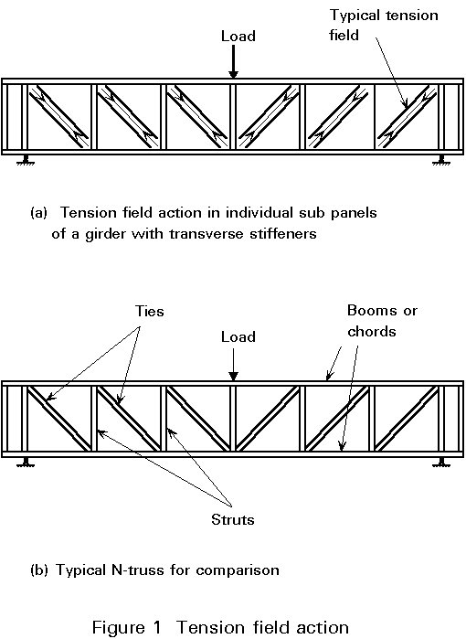
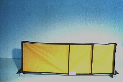
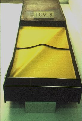
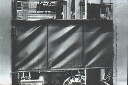
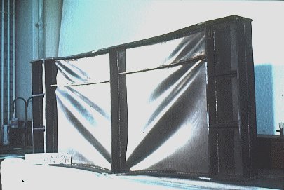
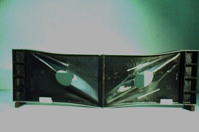
The satisfactory performance of a transverse stiffener can best be illustrated by comparing the girders shown, after testing, in Slides 1 and 2. In Slide 1 the stiffeners have remained straight and have clearly fulfilled the function of vertical struts in the simplified N-truss model of the post-buckling action discussed in Lecture 8.4.2, see Figure 1. In Slide 2 the stiffener has failed and has been unable to limit the buckling to the adjacent sub-panels of the girder; instead, the buckle has run through the stiffener position extending over both panels. Consequently, significant reduction in the failure load of the girder occurred.
Slide 1
Slide 2
The requirements to ensure adequate stiffener performance are given in Section 5.6.5 of Eurocode 3. First, the stiffener must be of adequate rigidity in the direction perpendicular to the plane of the web to prevent web buckling. This condition is satisfied provided the stiffener has a second moment of area Is that satisfies the following empirical formulae:
Is ³ 1,5 d3tw3 /a2 when a/d < ![]()
Is ³ 0,75 dtw3 when a/d ³ ![]()
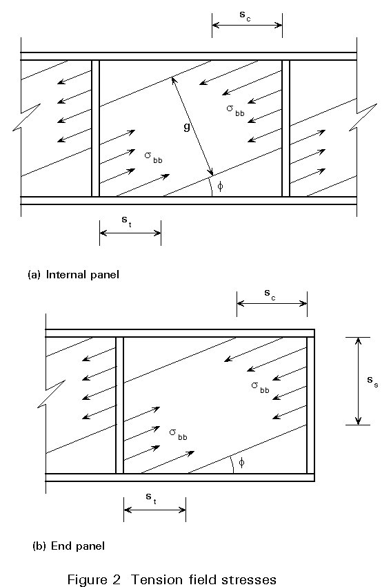
Secondly, the buckling resistance of the vertical "stiffener strut" must be sufficient to support the tension field forces shown in Figure 2a (which has been reproduced from Fig. 5.6.3a of Eurocode 3). It must also resist the resultant axial compressive force Ns that is imposed upon it. This force is calculated as follows:
Ns = Vsd - dtw tbb /gM1
where tbb is the initial shear buckling resistance of the web panels, calculated as given in Lecture 8.4.2. When the two web panels adjacent to the particular stiffener being designed are not identical, the lower value of tbb for the two panels should be taken. As previously, Vsd is the design value of the shear force.
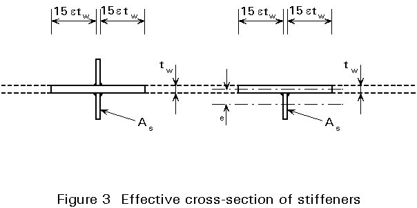
The buckling resistance of the stiffener strut to this axial compressive force is then calculated using Section 5.7.6 of Eurocode 3. Since the stiffener is attached to the web plate, a portion of the web acts effectively with the stiffener in resisting the axial compression. It is difficult to calculate the extent of this portion of the web but experimental observations have allowed an empirical effective web width of 30etw to be established, as shown in Figure 3 (which has been reproduced from Figure 5.7.4 of Eurocode 3). Having established the effective cross-section of the stiffener strut in this way, its buckling resistance is determined as for any other compression member according to Section 5.5.1 of the Eurocode.
For a "load bearing" stiffener, i.e. a transverse stiffener located at a position where an external load is applied to the girder, an additional consideration is necessary. The resistance of the effective cross-section of the load bearing stiffener should also be checked at a position close to the loaded flange.
The requirement for adequate boundary members to support the loading imposed by the post-buckling tension field is particularly onerous in the case of the end panel of the girder. The situation of the transverse stiffener at the end of the girder, i.e. the "end post", is very different from that of an intermediate stiffener, compare Figure 2b to Figure 2a. At the end of the girder, the forces imposed by the tension field in the end panel have to be resisted entirely by the end post without support from any further adjacent panels.
Design procedures for end panels and posts are given in Clauses 5.6.4.3 and 5.6.4.4 of Eurocode 3 [1]. Basically, they allow the designer two options.
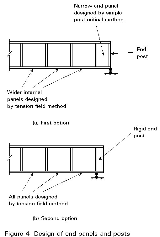
Firstly, the designer may choose not to design an end post that will provide adequate anchorage for the tension field. As a consequence, the end panel of the web must be designed according to the simple post-critical method so that a tension field does not develop within it. This option offers a simple design procedure but has the disadvantage that the calculated shear resistance of the end panel will be significantly lower than that of the internal web panels in the girder. Since it is probable that the applied shear in the end region will be higher than at any point on the span, this procedure will not provide an effective design solution if the stiffener spacing remains constant over the complete length of the girder. As shown in Figure 4a, the designer should then reduce the spacing of the stiffeners bounding the end panel so that the shear resistance of that panel as calculated by the simple post-critical method becomes equal to that calculated by the tension field method for the internal panels.
The more effective, but more complex, option is to design the end post to provide an adequate anchorage for the web tension field. The end panel of the web can then be designed according to the tension field method, so that the design shear buckling resistance (Vbb.Rd ) can be calculated as described in Lecture 8.4.2 for internal web panels, i.e.
Vbb.Rd = [(d tw tbb ) + 0,9 (g tw sbb sin f)]/gM1
The slight difference for the end panel arises in the calculation of the width g of the tension field. For an internal panel the width is given by:
g = d cos f - (a - sc - st) sin f
where, sc and st denote the lengths over which the tension field anchors onto the compression and tension flanges, see Figure 2a. For an end panel, the failure mechanism may be different since, as shown in Slide 3, a plastic hinge may also form in the end post.
Slide 3
This hinge affects the anchorage length for the compression flange which must now be calculated as:
sc = 
where Mpl.1 is the reduced plastic moment of the flange at the internal hinge position, allowing for the presence of the axial force (Nf1) at that position.
The other plastic hinge will form either at the end of the flange, as in the case of an internal panel, or in the end post. The location of the hinge, as defined by ss in Figure 2b, will depend upon which of these two elements has the lower plastic moment of resistance. Mpl.2 takes the lesser of these two values.
In this way, Clause 5.6.4.3 of Eurocode 3 allows the geometry of the tension field developed in the end panel to be fully defined, see Figure 2b. The design shear buckling resistance Vbb.Rd of the panel can then be calculated together with the horizontal component Fbb of the anchorage force of the tension field imposed on the end post:
Fbb = tw ss s bb cos2 f
The end post resists this force by acting as a vertical beam spanning between the two flanges. For this purpose it must satisfy the following criterion:
Mpl.2 + Mpl.3 ³ 0,5 Fbb ss
where the reduced plastic moment of the end post:
Mpl.3 = 0,25 bs ts2 fys {1 - [Ns3 /(bs ts fys )]2}
allows for the effect of the axial force in the end post:
Ns3 = Vsd - t bb tw (d - ss )
If it proves difficult to provide an end post in the form of a single plate to resist these forces, then the designer may consider providing an end arrangement such as that shown in Figure 4b. In this case, two transverse stiffeners are used. These two stiffeners and the portion of the web projecting beyond the end support form a rigid end post to provide the necessary anchorage for the tension field in the end panel. The disadvantage of such an arrangement is that adequate space must be available to allow the girder to project beyond its end support.
There are many situations where it is not possible to provide transverse web stiffeners at all points where vertical loads are applied to the girder. For example, a crane gantry girder is subjected to a vertical loading that travels along the flange; also, girders may be launched during construction so that the flange actually moves over the fixed point of support. In such cases, special consideration must be given to the design of the unstiffened web in the local region underneath, or above, the applied point or "patch" loading to prevent "web crippling". The webs of all beams must be checked for this possible local failure. Plate girders are particularly susceptible to this form of failure because of the slenderness of the web plates that are normally used in their construction.
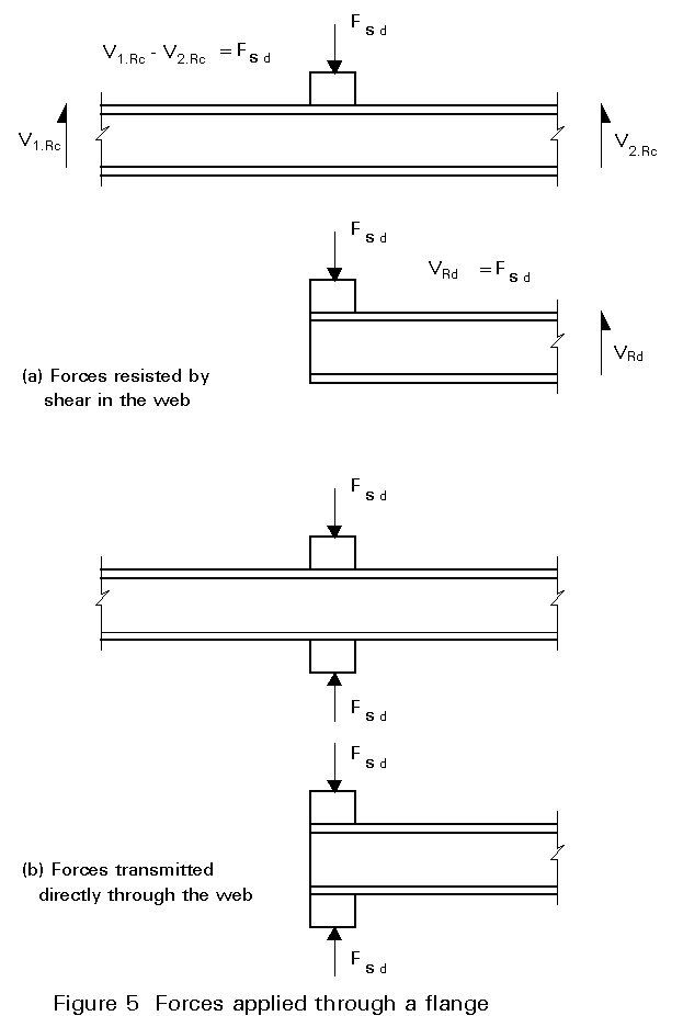
"Web crippling" is discussed in Section 5.7 of Eurocode 3. It distinguishes between the two different loading cases that are shown in Figure 5 (taken from Figure 5.7.1 of the Eurocode). In Figure 5a, the force is applied to one flange only and is therefore resisted by shear forces developed within the web plate. In this case the web plate has to be checked for its "crushing" and for its "crippling" resistance. In the other case, shown in Figure 5b, the force is applied to one flange, transmitted directly by compressive forces developed in the web, and resisted by a reactive force on the other flange. The web must again be checked for its "crushing" resistance. The "buckling" resistance of the web must also be considered in this case.
There are, therefore, three types of web resistance that must be calculated. In each case the resistance is dependent upon the length over which the applied force is effectively distributed on the flange. This is termed the "stiff bearing length" (ss ). It is calculated on the assumption of a dispersion of load through solid steel material at a slope of 1:1.
The terms "crushing", "crippling" and "buckling" resistance are introduced to differentiate between the phenomena being considered. In each case the appropriate resistance is calculated from empirical formulae:
"Crushing" resistance, where crushing is local yielding of the web without any buckling, is given by:
Ry.Rd = (ss + sy) tw fyw /gM1
"Crippling" resistance, where crippling is localised buckling of the web in the presence of plasticity, is given by:
Ra.Rd = 0,5 tw2 (E fyw )1/2 [tf /tw )1/2 + 3 (tw /tf ) (ss /d)]/gM1
"Buckling" of the web occurs with out-of-plane deformation over most of the depth of the web.
The "buckling" resistance (Rb.Rd ) for the compressive loading situation illustrated in Figure 5b is determined simply by considering the web plate as a vertical compression member. First it is necessary to determine the breadth of the web "strut" (beff ) that is effective in resisting the compression. This breadth may be calculated as:
beff = [h2 + ss2 ]1/2
where:
h is the overall depth of the girder.
ss is the stiff bearing length discussed above.
The buckling resistance of this idealised strut is then determined as for any other compression member according to Section 5.5.1 of Eurocode 3.
To increase the strength/weight ratio of plate girders, slender webs may be reinforced by longitudinal, as well as transverse, stiffeners. A typical longitudinally stiffened girder is shown after failure in Slide 4. The main function of the longitudinal stiffeners is to increase the buckling resistance of the web with respect of both shear and bending loads. An effective stiffener will remain straight, thereby sub-dividing the web panel and limiting the buckling to the smaller sub-panels. The resulting increase in the ultimate resistance of the girder can be significant.
Slide 4
The design of webs with longitudinal stiffeners is not covered in Part 1 of Eurocode 3. It will be addressed in Part 2, for bridges. Because of the greater need for high strength/weight ratios in bridges, girders with longitudinal stiffeners are more commonly encountered in bridge than in building construction.
Design of longitudinal stiffeners is usually based on a number of empirical design curves derived from the results of a parametric study employing numerical modelling techniques. The design procedure is relatively straightforward, although somewhat conservative. Additional information on the behaviour of longitudinally stiffened girders has been presented [2] which will assist the designer to gain a better understanding of the structural action.
Holes often have to be cut in the webs of plate girders used in building construction to provide access for service ducts, etc. No mention of such openings is made in Part 1 of Eurocode 3. Such holes have a particular influence on the behaviour of slender webs because the hole interrupts the tension field. (Design methods are available for stocky webs with web openings - see Reference3).
Detailed fundamental work by Narayanan [2] has shown that girders with slender webs and web openings possess a post-buckling reserve of resistance. The collapse mechanism for such girders, illustrated in Slide 5, is similar to the shear sway mechanism that is characteristic of all plate girders, as discussed in Lecture 8.4.2. However, some codes adopt a conservative approach. They do not take account of such post-buckling action in any girder which has a web opening with any dimension exceeding some percentage of the minimum dimension of the web panel in which it is located. To provide a simple design procedure, the shear resistance of the perforated panel is calculated as the buckling resistance.
Slide 5
The disadvantage of such a procedure is that the shear resistance of the perforated panel will then be substantially lower than that calculated allowing for the full post-buckling reserve of resistance in adjacent unperforated panels. The designer should therefore reduce the spacing of the transverse stiffeners either side of the web opening so that the initial buckling resistance of the resulting narrow perforated panel is approximately equal to the full post-buckling resistance of adjacent panels.
[1] Eurocode 3 "Design of Steel Structures".
European Prestandard ENV1993-1-1: Part 1.1, General rules and rules for buildings, CEN, 1992.
[2] Narayanan, R (Editor), "Plated Structures; Stability and Strength", Applied Science Publishers, London, 1983.
This reference gives detailed information, including the experimental background to the structural action covered in the clauses of Eurocode 3 referred to in this lecture.
[3] Lawson, R. M., Design for Openings in the Webs of Composite Beams, SCI Publication 068. The Steel Construction Institute, 1987.