ESDEP WG 8
PLATES AND SHELLS
To present the basic design methods for plate girders subjected to either shear or moment, or a combination of both.
Lecture 8.4.1: Plate Girder Behaviour and Design I
Lecture 7.3: Local Buckling
Lecture 7.8.1: Restrained Beams I
Lecture 7.8.2: Restrained Beams II
Lecture 7.9.1: Unrestrained Beams I
Lecture 7.9.2: Unrestrained Beams II
Lecture 8.4.3: Plate Girder Design - Special Topics
The design methods for plate girders subject to bending and shear, according to the methods of Eurocode 3[1], are presented. For shear loading two methods are described: the "simple post-critical method", and the "tension field method"; interaction diagrams can be used with both methods to allow for the effect of coincident moments.
Any cross-section of a plate girder is normally subjected to a combination of shear force and bending moment. The primary function of the top and bottom flange plates of the girder is to resist the axial compressive and tensile forces arising from the applied bending moment. The primary function of the web plate is to resist the applied shear force.
Plate girders are normally designed to support heavy loads over long spans in situations where it is necessary to produce an efficient design by providing girders of high strength to weight ratio. The search for an efficient design produces conflicting requirements, particularly in the case of the web plate. To produce the lowest axial flange force for a given bending moment, the web depth (d) must be made as large as possible. To reduce the self weight, the web thickness (tw) must be reduced to a minimum. As a consequence, in many instances the web plate is of slender proportions and is therefore prone to buckling at relatively low values of applied shear. A similar conflict may exist for the flange proportions. The required flange area is defined by the flange force and material yield stress. The desire to increase weak axis second moment of area encourages wide, thin flanges. Such flanges are prone to local buckling.
Plate elements do not collapse when they buckle; they can possess a substantial post-buckling reserve of resistance. For an efficient design, any calculation relating to the ultimate limit state should take the post-buckling action into account. This is particularly so in the case of a web plate in shear where the post-buckling resistance arising from tension field action can be very significant.
Thus, in designing a plate girder it is necessary to evaluate the buckling and post-buckling action of webs in shear, and of flange plates in compression. The design of plate girder flanges largely follows procedures already discussed in Lecture 7.8, Lecture 7.9.1, and Lecture 7.9.2 for beams. However, the design of web plates operating in the post-buckling range is very different and will be discussed here in some detail. The lecture will start by concentrating upon the resistance of plate girders to predominantly shear loading. The effects of high co-existent bending moments will be considered.
The lecture will concentrate only on the main aspects of girder design assuming a basic cross-section. In particular, it is assumed that:
Lecture 8.4.3 considers other important cases that do not comply with the above assumptions.
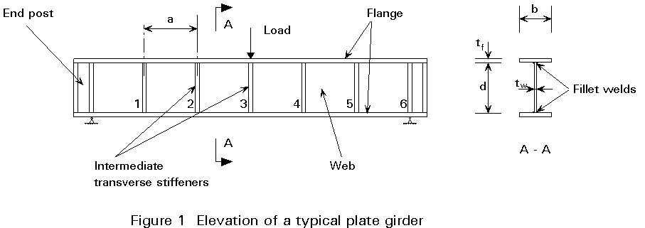
A typical transversely stiffened plate girder is shown diagrammatically in Figure 1, which also defines the notation used. The shear buckling resistance of the web depends mainly on the depth to thickness ratio (d/tw), and upon the spacing (a) of the transverse web stiffeners.
Intermediate transverse stiffeners are normally employed to increase the shear buckling resistance of the web, although designers may sometimes choose to use a thicker web plate rather than incur the additional fabrication costs arising from the use of intermediate stiffeners. Girders without intermediate stiffeners are normally termed "unstiffened" girders, even though they will normally have stiffeners at points of support and possibly at the position of load application.
Web buckling should be checked in all cases where the depth to thickness ratio, (d/tw), of the web exceeds 69e . Eurocode 3 then offers the choice of 2 methods for plate girder design. The methods are:
a) the simple post-critical method, which may be applied to both stiffened and unstiffened girders and is therefore of general application.
b) the tension field method, which may only be applied to girders with intermediate transverse stiffeners. Even for such girders its range of application is limited to a range of stiffener spacing defined by:
1,0 £ a/d £ 3,0
There is now considerable evidence [2] that tension field action does develop in girders where the stiffener spacing lies outside this range, and also in unstiffened girders; such evidence, however, has yet to be presented in a form that is suitable for inclusion in a design code.
The simple post-critical method is seen as a general-purpose method which can be applied to the design of all girders. The tension field method, on the other hand, can be applied to a certain range of girders only, but will lead to considerably more efficient designs for these girders, because it takes full account of the post-buckling reserve of resistance. Each method will now be discussed.
This simple approach allows the design shear buckling resistance (Vba.Rd) to be determined directly as follows:
Vba.Rd = d tw tba/gM1 (1)
where all the terms in the expression are familiar, except the post-critical shear strength, tba. The calculation of this term depends upon the slenderness of the web which may be conveniently expressed by the following parameter:
![]() (2)
(2)
Here, kt is a shear buckling factor calculated from elastic buckling theory [3]. For simplicity, it is conservatively assumed in this calculation that the boundaries of the web panel are simply supported, since the true degree of restraint offered by the flanges and adjacent web panels is not known. The resulting expression obtained for the shear buckling factor is dependent upon the spacing of the transverse web stiffeners as follows:
for closely spaced intermediate stiffeners (a/d < 1,0) :
kt = 4 + ![]()
for widely spaced intermediate stiffeners (a/d ³ 1,0) :
kt = 5,34 + ![]()
for unstiffened webs: kt = 5,34
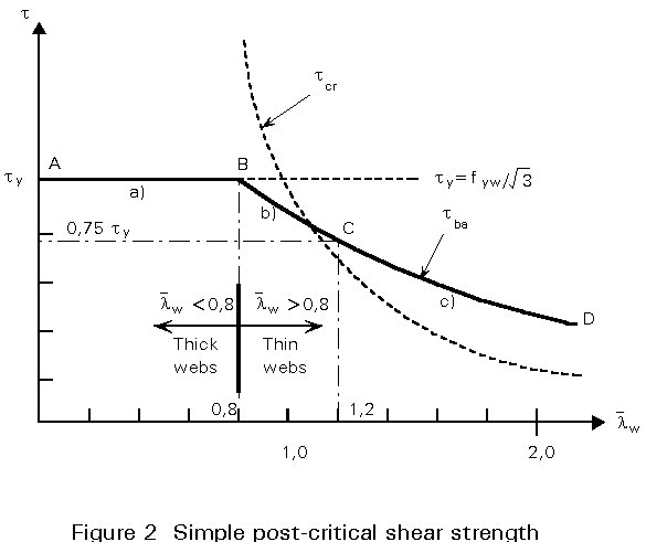
Knowing the shear buckling factor, the slenderness parameter is determined from Equation (2) and the calculation of the post-critical shear strength then depends, as illustrated in Figure 2, upon whether the web is:
a) stocky or thick (![]() w
£ 0,8 , region AB in Figure 2) in which case the web will not buckle and the shear stress at failure will reach the shear yield stress of the web material:
w
£ 0,8 , region AB in Figure 2) in which case the web will not buckle and the shear stress at failure will reach the shear yield stress of the web material:
tba = fyw/![]()
where fyw is the tensile yield strength
b) intermediate (0,8 < ![]() w
< 1,2, region BC in Figure 2) which represents a transition stage from yielding to buckling action with the shear strength being evaluated empirically from the following:
w
< 1,2, region BC in Figure 2) which represents a transition stage from yielding to buckling action with the shear strength being evaluated empirically from the following:
tba = [1 - 0,625 (![]() w
- 0,8)] (fyw/
w
- 0,8)] (fyw/![]() )
)
c) slender or thin (![]() w
³ 1,2, region CD in Figure 2) in which case the web will buckle before it yields and a certain amount of post-buckling action is taken into account empirically:
w
³ 1,2, region CD in Figure 2) in which case the web will buckle before it yields and a certain amount of post-buckling action is taken into account empirically:
tba = 
The calculation of the shear buckling resistance by the simple post-critical method is then completed by substitution of the appropriate value of tba into Equation (1).
For transversely stiffened girders where the transverse stiffener spacing lies within the range 1,0 £ a/d £ 3,0, full account may be taken of the considerable reserve of post-buckling resistance. This reserve arises from the development of "tension field action" within the girder.
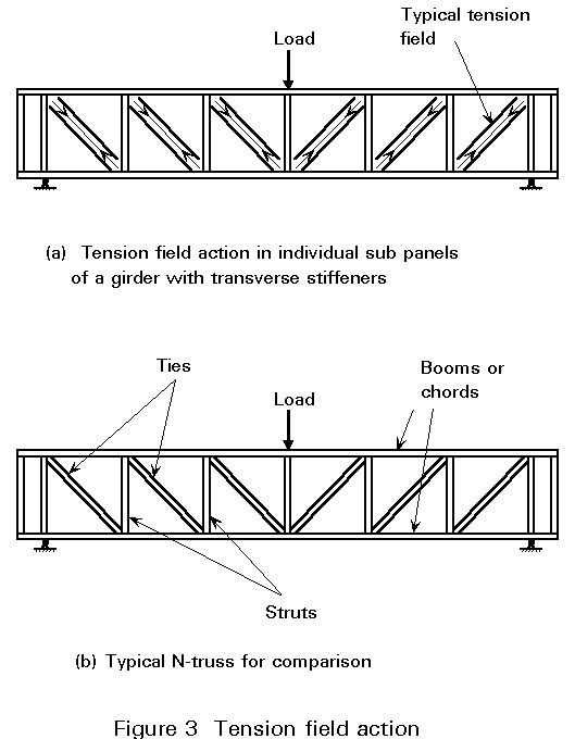
Figure 3a shows the development of tension field action in the individual web panels of a typical girder. Once a web panel has buckled in shear, it loses its resistance to carry additional compressive stresses. In this post-buckling range, a new load-carrying mechanism is developed, whereby any additional shear load is carried by an inclined tensile membrane stress field. This tension field anchors against the top and bottom flanges and against the transverse stiffeners on either side of the web panel, as shown. The load-carrying action of the plate girder than becomes similar to that of the N-truss in Figure 3b. In the post-buckling range, the resistance offered by the web plates is analogous to that of the diagonal tie bars in the truss.
The total shear buckling resistance for design (Vbb.Rd) is calculated in Eurocode 3, by superimposing the post-buckling resistance upon the initial elastic buckling resistance as follows:
Total shear resistance = elastic buckling resistance + post-buckling resistance:
Vbb.Rd = (d tw tbb)/gM1 + 0,9 (gtw sbb sin f)/gM1 (3)
The basis for this assumed behaviour is shown diagrammatically in Figure 4.
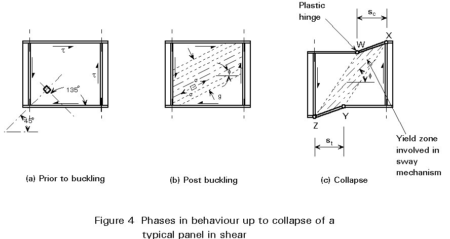
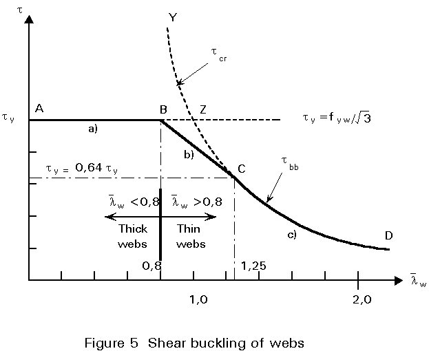
Figure 4a shows the situation prior to buckling, as represented by the first term in Equation (3). At this stage, equal tensile and compressive principal stresses are developed in the web. The shear buckling strength, tbb, is calculated from elastic buckling theory and leads to equations similar, but not identical, to those given earlier in Section 2.1 for the simple post-critical shear strength tba. Thus, the calculation of the shear buckling resistance again depends, as shown in Figure 5, upon whether the web is:
a) stocky or thick (![]() w
= 0,8, region AB in Figure 5) in which case the web will not buckle and the shear yield stress is again taken:
w
= 0,8, region AB in Figure 5) in which case the web will not buckle and the shear yield stress is again taken:
tbb = fyw/![]()
where fyw is the tensile yield strength
b) intermediate (0,8 < ![]() w
< 1,25, region BC in Figure 5) where, in the transition from yield to buckling:
w
< 1,25, region BC in Figure 5) where, in the transition from yield to buckling:
tbb = [1 - 0,8 (![]() w
- 0,8)] (fyw/
w
- 0,8)] (fyw/![]() )
)
c) slender or thin (![]() w
³ 1,25, region CD in Figure 5) where the web will buckle and, from elastic buckling theory:
w
³ 1,25, region CD in Figure 5) where the web will buckle and, from elastic buckling theory:
tbb = [1/![]() w2][fyw/Ö3]
w2][fyw/Ö3]
Thus, knowing tbb, the first term of the expression in Equation (3) can be evaluated.
The evaluation of the second term, corresponding to the post-buckling action, is more complex although it may still be reduced to a convenient design procedure, as described below.
In the post-buckling range, as shown in Figure 4b, an inclined tensile membrane stress field is developed, at an inclination f to the horizontal. Since the flanges of the girder are flexible, they will begin to bend inwards under the pull exerted by the tension field.
Further increase in the load will result in yield occurring in the web under the combined effect of the membrane stress field and the shear stress at buckling. The value of the tension field stress (sbb) at which yield will occur, termed the "strength of the tension field" in Eurocode 3, may be determined by applying the Von Mises-Hencky yield criterion [2]. This results in the following expression for the strength of the tension field:
s
bb = [fyw2 - 3t2bb + y2] 0.5 - ywhere the term y = 1,5 tbb sin 2f is introduced for convenience only.
Once the web has yielded, final failure of the girder will occur when the mechanism comprising 4 plastic hinges has formed in the flanges, as shown in Figure 4c. A detailed analysis of this collapse mechanism, by considering the internal forces developed in the web and imposed upon the flanges (see [2]) allows the width (g) of the tension field, which appears in the second term of Equation (3), to be evaluated:
g = d cos f - (a - sc - st) sin f
where, as in Figure 4c, sc and st denote the positions at which the plastic hinges form in the compression and tension flanges respectively.
The hinge positions are calculated [2] from the knowledge that the hinges will form at the point of maximum moment, and therefore zero shear, in the flanges; the appropriate expression is as follows:
S = [2/sin q][MNf.Rk/tw sbb]1/2 £ a (4)
where MNf.Rk is the plastic moment of resistance of the flange, i.e. 0,25 btf2 fyf. When high bending moments are applied to the girder, in addition to shear, then axial forces (Nf.Sd) will be developed in the flanges. Such axial forces will, of course, reduce the plastic moment of resistance of the flanges. Their effects can be calculated from standard plasticity theory as:
MNf.Rk = 0,25 btf2 fyf {1 - [Nf.Sd / (btf fyf /gmo )]2} (5)
All the terms required for the calculation of the total shear resistance from Equation (3), other than the inclination f of the tension field, are now known. Unfortunately, the value of f cannot be determined directly and an iterative procedure has to be adopted in which successive values of f are assumed and the corresponding shear resistance evaluated in each case. The process is repeated until the value of f providing the maximum, and therefore the required, value of the shear resistance has been established. The variation of the shear resistance with f is not very rapid. The correct value of f lies between a minimum of q/2 and a maximum of q, where q is the slope of the panel diagonal tan-1(d/a), as shown in Figure 6. A parametric study [2] has established that, for girders of normal proportions, the value of f which produces the maximum value of shear resistance is approximately given by:
f
= q /1,5
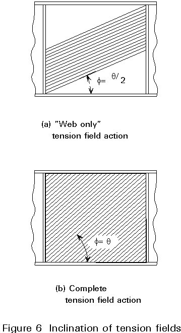
The assumption of this value of f will lead either to the correct value or to an underestimation of the shear resistance. It will therefore give a safe approximation and will also give a good starting value of f if a more accurate process of iteration is to be carried out. The correct value of f is that which gives the maximum value of Vbb.Rd.
In general, any cross-section of a plate girder will be subjected to bending moment in addition to shear. As discussed in [2], this combination makes the stress conditions in the girder web considerably more complex. In the first place, the stresses from the bending moment will combine with the shear stresses to give a lower buckling load. Secondly, in the post-buckling range, the bending stresses will influence the magnitude of the tension field membrane stresses required to produce yield in the web. Finally, as already discussed with reference to Equation (5), the axial flange forces arising from the bending moment will reduce the plastic moment of resistance of the flanges.
The proper evaluation of all these effects is complex but, as discussed in [2], certain assumptions may be made about the interaction of moment and shear to produce a simple and effective design procedure. In Eurocode 3, the procedure for allowing for moment/shear interaction naturally depends upon whether the simple post-critical method of Section 2.1 or the tension field method of Section 2.2 is being used to calculate the shear buckling resistance. Each case will now be considered separately.
The interaction between shear and bending can be conveniently represented by the diagram shown in Figure 7a (Figure 5.6.4a of Eurocode 3) where the shear resistance of the girder is plotted on the vertical axis and the moment resistance is plotted horizontally. The interaction represents a failure envelope, with any point lying on the curve defining the co-existent values of shear and bending that the girder can just sustain.
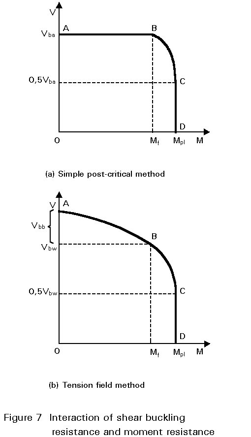
The interaction diagram can be considered in 3 regions. In region AB, the applied bending moment Mad is low and the girder can then sustain a shear load Vad that is equal to the full value of the shear buckling resistance calculated from the simple post-critical method, as in Equation (1). Thus, in this region:
Msd £ Mf.Rd
Vsd £ Vba.Rd (6)
The moment that defines the end of the range at point B (Mf.Rd) is the plastic moment of resistance of the cross-section consisting of the flanges only, i.e. neglecting any contribution from the web. In this calculation it is necessary to appreciate that the plates of the compression flange may buckle and, if necessary, to take this into account by adopting an effective width beff for the flange. The calculation of this effective width is as described in Lecture 7.3 for an outstand element in compression.
At the other extreme of the interaction diagram in region CD, the applied shear Vad is low. Provided it does not exceed the limiting value of 0,5 Vba at point C then the plastic moment of resistance of the complete cross-section Mpl.Rd need not be reduced to allow for shear.
In the intermediate region BC the co-existent applied moment MSd and shear VSd values must satisfy the following relationship:
MSd £ Mf.Rd + (Mpl.Rd - Mf.Rd) [1 - (2VSd/Vba.Rd - 1)2] (7)
The complete range of moment/shear interaction has thus been defined for the simple post-critical method.
The procedure for the tension field method follows that described above for the simple post-critical method. It leads to the construction of a similar, though not identical, interaction diagram, see Figure 7b (Figure 5.6.4b of Eurocode 3).
In the low moment region AB, again defined by values of the applied moment less than Mf.Rd, the girder can sustain a shear load Vad that is equal to the "web only" shear resistance Vbw.Rd calculated from tension field theory. Thus:
MSd £ Mf.Rd
VSd £ Vbw Rd
The "web only" shear resistance is the specific value of the total shear resistance Vbw.Rd calculated from Equation (1), for the case when MNf.Rk in EC3=0 in Equation (5). This is, in effect, a conservative approach which neglects the contribution of the flanges to the tension field action.
At the other extreme in region CD, the procedure remains as for the simple post-critical method except that the limiting value of shear at point C is now taken as 0,5Vbw. Similarly, the procedure for the intermediate region BC remains as before except that the substitution of the tension field value Vbw for Vba in Equation (7) gives:
MSd £ Mf.Rd + (Mpl.Rd - Mf.Rd) [1 - (2VSd / Vbw.Rd - 1)2] (8)
The complete range of moment/shear interaction is thus defined for the tension field method.
[1] Eurocode 3 "Design of Steel Structures": European Prestandard ENV1993-1-1: Part 1.1, General rules and rules for buildings, CEN, 1992.
[2] Narayanan, R. (ed), "Plated Structures; Stability and Strength", Applied Science Publishers, London 1983.
Chapter 1 covers basic aspects of plate girder behaviour and design.
[3] Bulson, P. S. "The Stability of Flat Plates", Chatto & Windus, London, 1970.
General coverage of plate buckling and explanation of kt values for numerous cases.
Chapters 4 and 5 provide a detailed coverage of plate girder design, taking the reader well beyond the content of this lecture. They also refer to numerous original sources.