ESDEP WG 11
CONNECTION DESIGN: STATIC LOADING
To describe the different types of structural welds and give basic information on weld preparation and weld quality.
Lectures 1B.5: Introduction to Design of Buildings
Lecture 2.1: Characteristics of Iron-Carbon Alloys
Lectures 2.3: Engineering Properties of Steels
Lectures 3.2: Erection
Lecture 3.5: Fabrication/Erection of Buildings
Lecture 3.6: Inspection/Quality Assurance
Lecture 11.1.2: Introduction to Connection Design
Lecture 2.4: Steel Grades and Qualities
Lecture 2.6: Weldability of Structural Steels
Lecture 3.3: Principles of Welding
Lecture 3.4: Welding Processes
Lectures 11.2: Welded Connections
Lectures 11.4: Analysis of Connections
Mechanical and geometrical characteristics of welds are described. Fundamental principles concerning edge preparation, fit-up, and quality of welds are given.
NOTATION
As% Elongation of steel at failure
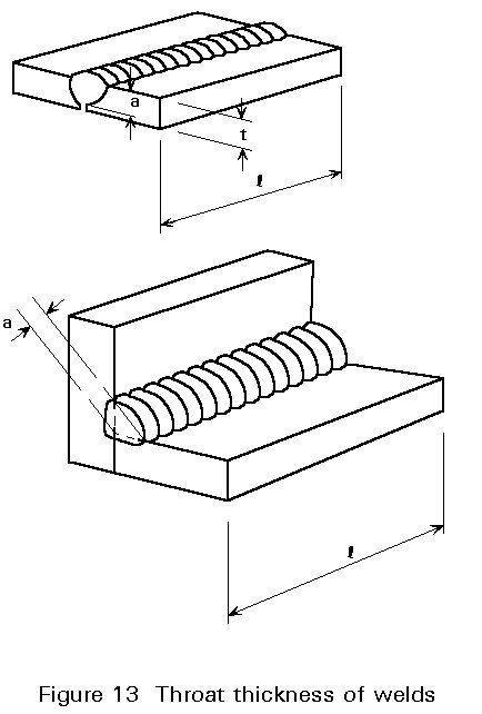
a Throat thickness of welds [mm]
fy Nominal yield stress of parent metal [MPa]
fu Nominal ultimate stress of parent metal [MPa]
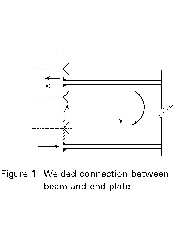
Where there are favourable working conditions, welding is the most economical way to make strong connections. Therefore, workshop connections are usually welded. Where site connections are necessary (erection) they are usually bolted, but the connections are often prepared in the workshop with welded plates, etc. necessary for the bolted joint.
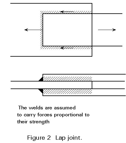
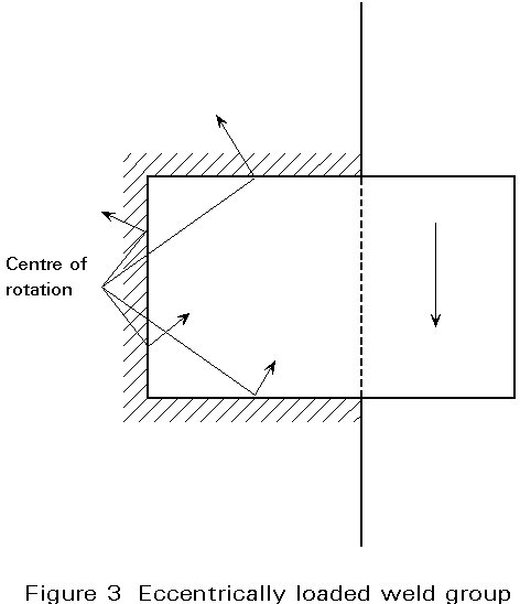
Figures 1-3 show some examples on welded connections and the way they carry external loads.
In welded construction for buildings approximately 80% of the welds are fillet welds and 15% are butt welds. The remaining 5% are plug, slot and spot welds.
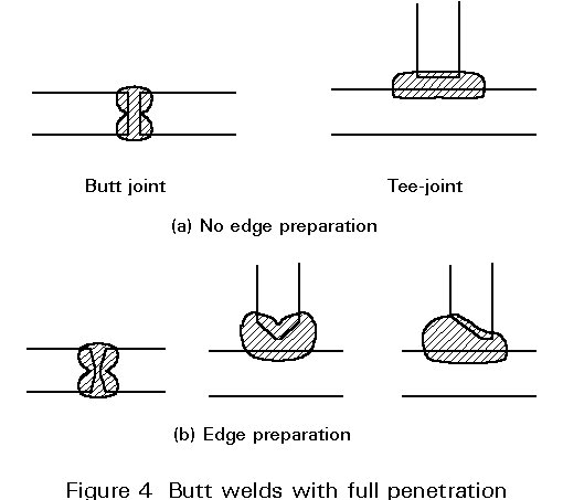
A butt weld is made within the cross-section of the abutting plates in a butt or tee joint. Normally, the plate edges have to be prepared before welding, see Figure 4b. In some cases, if the plate thickness is less than about 5mm, edge preparation can be avoided, see Figure 4a.
The bevelled plate edges in a butt weld may take various geometrical forms, see Figure 5.
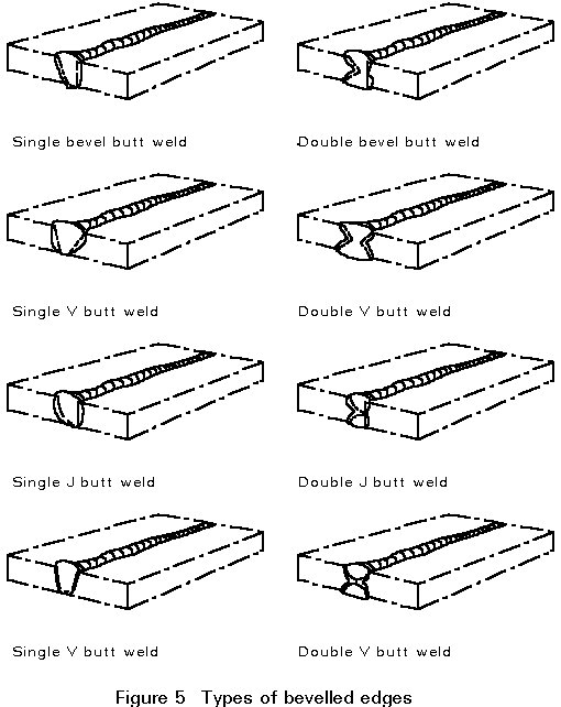
For butt welds, a distinction is made between:
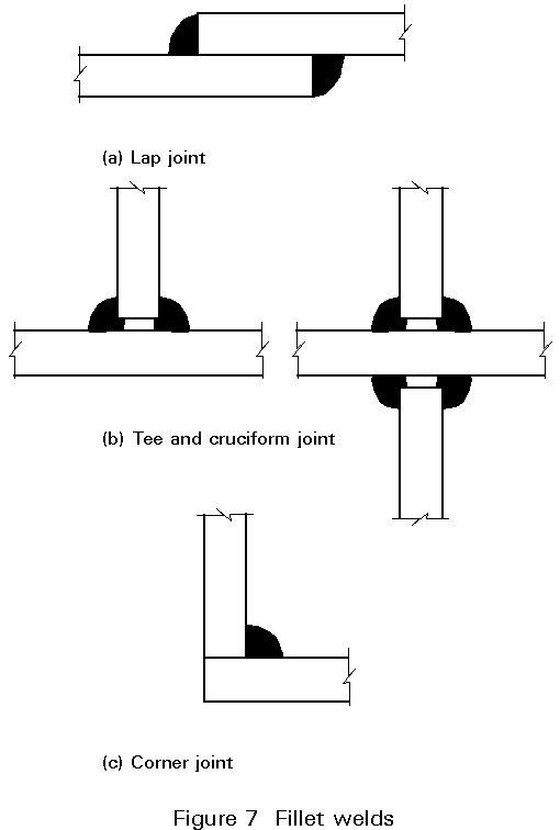
A fillet weld is a weld of approximately triangular cross-section applied to the surface profile of the plates. No edge preparation is needed. Therefore, fillet welds are usually cheaper than butt welds. According to the relative position of the parts to be welded, there are three types of fillet weld applications:
Fillet welds that can be laid in a single run are particularly economic; in the workshop 8mm welds are often possible but if site welding is to be used this figure may be reduced e.g. to 6mm.
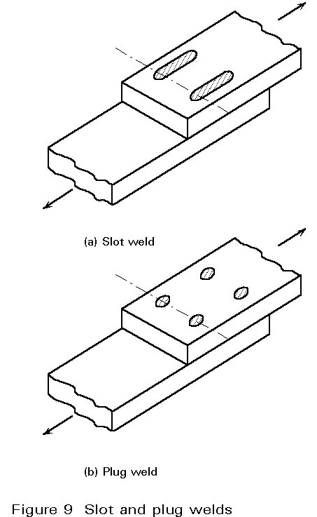
Slot and plug welds, see Figure 9, are seldom used in building structures. They principally prevent buckling or separation of lapped plates.
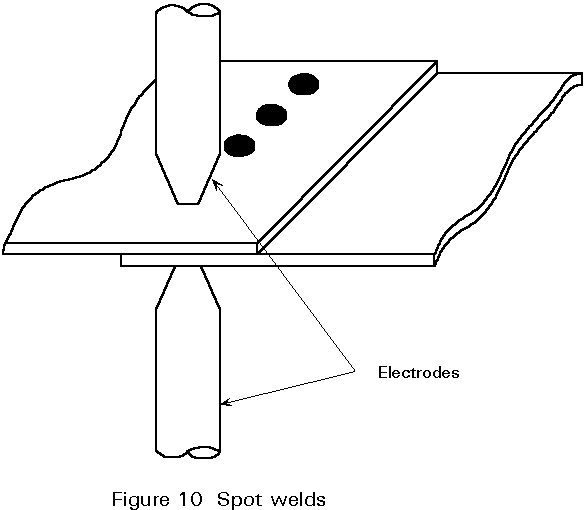
Spot welds are seldom used in building structures. The parts to be joined, which must be thin, are clamped together by two electrodes, see Figure 10. A current passing through the electrodes melts the pieces locally, and the clamping pressure forces them together, forming a fused spot. A line of such spots constitutes a joint.
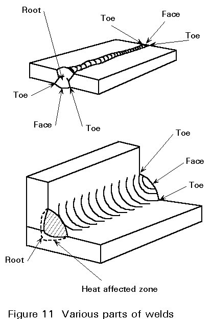
In this chapter some terms often used in weld design are defined.
Figure 11 shows the terminology used to describe the various parts of the weld:
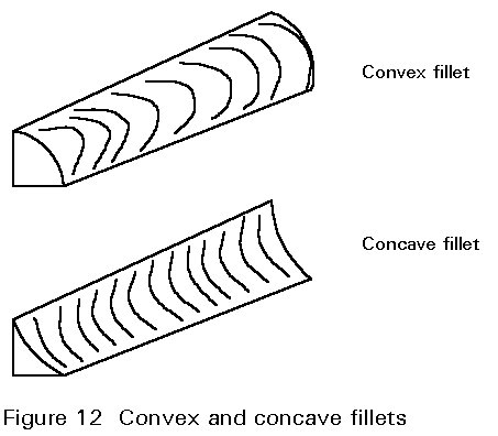
The shape of a fillet welded cross-section can be convex or concave, see Figure 12.
For design, two geometrical weld parameters are used:
The parent metal must have the weldability properties defined by the steel qualities of each steel grade. The weldability of a steel depends on its chemical composition and metallurgical characteristics. These aspects are described in Lecture 2.6.
In accordance with Eurocode 3 [1] and EN 10025 [2], hot-rolled steel grades S235, S275 and S355 with quality B, C or D are suitable for all welding processes.
The mechanical characteristics adopted in calculations are the yield strength fy and the ultimate tensile strength fu. Further, in the case of plastic analysis, steel must have an ultimate strain at least 20 times the yield strain and have a minimum elongation As at failure of at least 15%. The values of these characteristics are given in Table 1.
|
Nominal steel grade |
Thickness t |
|||||
|
t < 40mm |
40 mm < t < 100mm |
|||||
|
fy MPa |
fu MPa |
As % |
fy MPa |
fu MPa |
As % |
|
|
Fe 360 Fe 430 Fe 510 |
235 275 355 |
360 430 510 |
26 22 22 |
215 255 335 |
340 410 490 |
24 20 20 |
Table 1 - Mechanical properties of hot rolled steels
The steel quality B, C, or D reflects the impact resistance determined by a Charpy-V impact test in which the impact energy needed to fracture a V-notch specimen with a certain temperature is measured. The quality class indicates if the steel is suitable for the application. For example, steel quality B, corresponding to an impact test at +20°C, is used for structures with normal working conditions. The steel quality D (impact test at -20°C) is suitable when factors such as, for example, low service temperature of the structure, thick steel material and/or impact loading are present.
According to Eurocode 3 the filler metal must have mechanical properties (yield strength, ultimate tensile strength, elongation at failure and minimum Charpy V-notch energy value) equal to or better than the values specified for the steel grade being welded.
The selection of welding consumable is to a great extent governed by the welding process, see Lectures 3.3 and 3.4. The basic principles are:
Some important aspects, which are described in detail in Lectures 3.3, 3.4 and 3.5, are summarised here.
One of the following arc welding processes may be used:
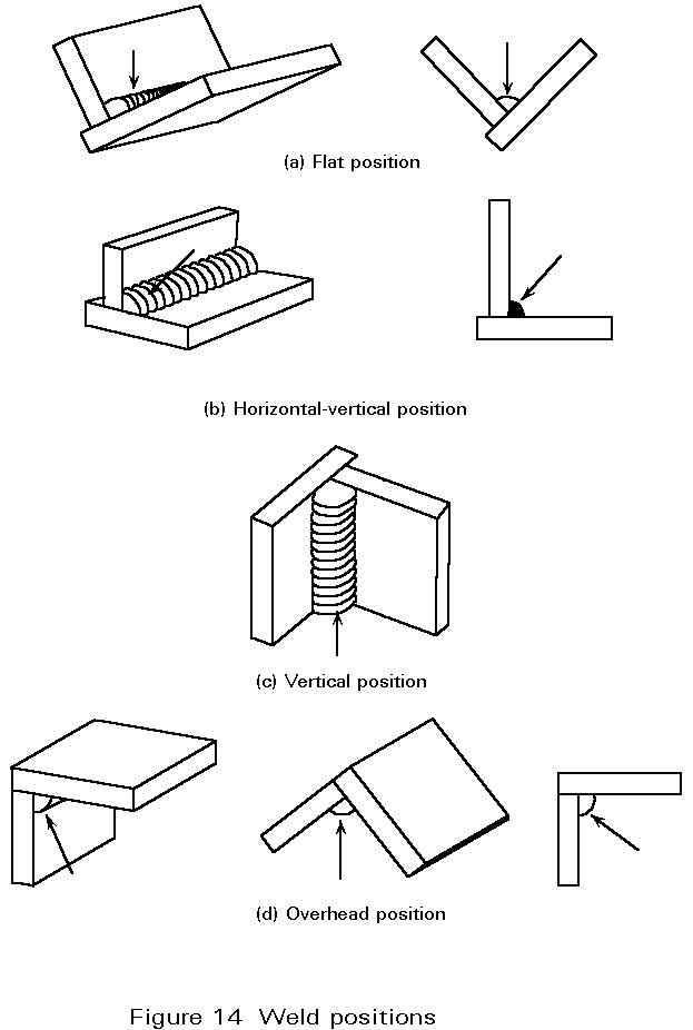
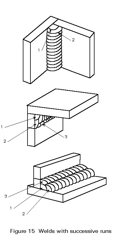
All these processes can be used in the workshop. Usually, only bolting or metal arc welding with covered electrodes is employed in the erection phase on the building site. With the metal arc welding process, welds can be made in all positions. The various weld positions are shown in Figure 14, where the arrows give the arc direction during the welding operation. It is clear that welding in the flat position is easily carried out, allowing a greater rate of metal deposition than the other positions;by welding in this favourable position, the maximum size of weld run can be obtained. With ordinary welding consumables and favourable welding conditions, a fillet weld with a throat thickness of 6mm can be produced with only one run. For welds of greater thickness, more than one run is necessary. In this case, the welding sequence must be carefully planned, see Figure 15.
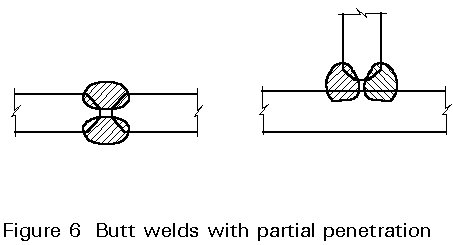
The welding conditions, particularly the current limitation of the welding equipment, constitute a limit to the depth of penetration into the parent plate. For example, if a closed butt joint (no gap between the two plates) is welded with one run on each side, the penetration may not be complete and the central part of the joint will remain unfused (Figure 16a). With a gap between the two parts of the joint, full penetration can be achieved with the same welding equipment. The limitation is then set by the thickness of the plates to be joined. In practice, the limit for butt welds with square edges, i.e. without preparation, is 10mm plate thickness with a 5mm gap. When the plate thickness exceeds this value, bevelled edges permit full penetration by several runs, see Figure 16b.

Edge preparation consists essentially of cutting and bevelling the edges of the plates which are to be welded. These operations can be done by thermal cutting, by machining or by chipping or grinding. The resulting surfaces of the bevelled edges should be smooth, uniform, free from cracks and without rust. If thermal cutting or another process which hardens the material is used, the approved welding procedure must take account of this weld preparation process. Different bevel geometries are shown in Figure 3. Practical recommendations, for example Eurocode 3, Annex W (1), give some tolerance values for various weld types. Finally, before welding, surfaces and edges adjacent to the weld location must be cleaned to remove oil, grease, paint or any other contaminants, which can affect the quality of the weld and the weld strength.
The appropriate welding method and procedure are defined in a project specification provided by the designer, see Lecture 11.5.
Quality control has been for some time an important part of industrial activity. The term quality includes all the characteristics of a product which affect its ability to serve its purpose. In the lectures of Working Group 3, and particularly in Lecture 3.4, attention is drawn to quality control applied to welding, including the qualification of firms and the procedure qualification for welding tests.
Normally, all welded structures undergo some weld inspection. The type and the extent for the inspection, as well as the choice of welds to be inspected are selected in accordance with the project specification.
The principal purpose of weld inspection is to discover possible weld defects. Examples on weld defects are, see Figure 17:
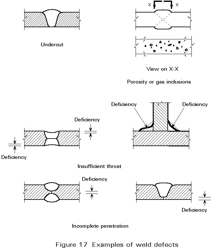
All these defects can be measured. Codes of Practice specify the allowable tolerances for each defect, see for example Eurocode 3, Annex W [1].
[1] Eurocode 3: "Design of steel structures": ENV 1993-1-1: General rules and rules for buildings, CEN, 1992.
[2] En 10025: European Standard 10025, Hot rolled products of non-alloy structural steels - technical delivery conditions.