ESDEP WG 11
CONNECTIONS DESIGN: STATIC LOADING
To present the general methods for conducting calculations to determine the strength of butt and fillet welds.
Lectures 1B.5: Introduction to Design of Buildings
Lecture 2.1: Characteristics of Iron-Carbon Alloys
Lecture 2.3: Engineering Properties of Steels
Lecture 3.2: Erection
Lecture 3.5: Fabrication/Erection of Buildings
Lecture 3.6: Inspection/Quality Assurance
Lecture 11.1.2: Introduction to Connection Design
Lecture 11.2.1: Generalities on Welded Connections
Lecture 2.4: Steel Grades and Qualities
Lecture 2.6: The Weldability of Structural Steels
Lecture 3.3: Principles of Welding
Lecture 3.4: Welding Processes
Lectures 11.4: Analysis of Connections
The bases for the calculation of weld strength are set out. A large part of the lecture deals with the actual stress distribution and the deformability of fillet and butt welds. Some experimental results are presented to show the relevance of the design formulae.
NOTATION
a throat thickness of weld [mm]
F external force [N]
Fs^ normal force perpendicular to the plane of the throat area of the weld [N]
Ft^ shear force in the plane of the throat area transverse to the weld axis [N]
Ft// shear force in the plane of the throat area parallel to the weld axis [N]
fu nominal ultimate tensile stress of parent metal [MPa]
fvw design shear strength of weld [MPa]
Lj length of lap joint [mm]
Lw length of weld (in long joint) [m]
l length of weld [mm]
b
w correlation factorb
LW reduction factor for long weldg
MW partial safety factor for weldss
1 normal stress perpendicular to the plane of the throat area of the weld [MPa]s
2 normal stress parallel to the axis of the weld [MPa]s
eq equivalent stress [MPa]t
1 shear stress in the plane of the throat area transverse to the weld axis [MPa]t
2 shear stress in the plane of the throat area parallel to the weld axis [MPa]The purpose of this lecture is to present the basis for weld strength calculation according to Eurocode 3 [1], to discuss the assumptions on which the methods are based and to examine the general methods used to determine stresses in welds. In practice, weld calculations are principally concerned with fillet welds since these account for approximately 80% of all structural welds. For this reason the lecture concentrates on fillet welds and gives less attention to other weld types (butt, slot, plug).
For weld design, three fundamental assumptions are made [2]:
These assumptions lead to a uniform stress distribution in the weld, whereas variation of stress and strain are observed along the weld. In fact, stress concentrations and residual stresses can reach the yield stress locally. However, the ductility of the material leads to a redistribution of stresses along the weld length, producing an appreciable reduction of stress magnitude. The redistribution also occurs when the weld is subject to the action of external loads. According to the theory of plasticity, the final stress distribution will be optimum when the yield stress is reached over the full length of the weld.
Eurocode 3 [1] specifies that the filler metal shall have mechanical properties (yield strength, ultimate tensile strength, elongation at failure and minimum Charpy V-notch energy value) equal to, or better than, the corresponding properties of the parent material. Therefore, for weld calculation and design, the strength of the parent material is normally taken as the reference strength.
Although fillet welds are the more important case, butt welds are treated first since the design requirements are simpler.
Providing the welding process has been correctly carried out, the butt weld filler metal may be considered as parent metal. Hence, to determine the resistance of the joint, the calculation is based on the throat area, i.e. the penetration area. Depending on the penetration, two kinds of butt welds are defined: full and partial penetration welds.
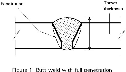
For a full penetration butt weld, calculation is not necessary because the filler metal strength is at least as high as the parent metal strength of the weaker part joined and the throat thickness of the weld is equal to the thickness of the plate, see Figure 1. Thus the butt weld may effectively be regarded simply as replacing the parent material.
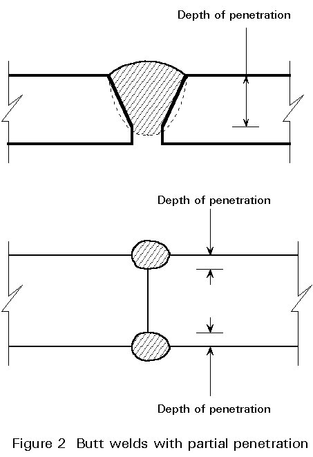
For a partial penetration butt weld, the throat thickness considered in the design is the depth of preparation, slightly reduced. According to Eurocode 3 [1], the throat thickness must be taken as the depth of the butt preparation minus 2mm, where the preparation is the depth of the bevel, see Figure 2. However, if appropriate procedure trials have been made, the throat thickness can be taken as equal to the preparation.
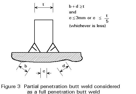
A partial penetration tee-butt joint with superimposed fillet welds may be considered as a full penetration butt weld, if the total throat thickness is greater than the material thickness and the gap dimension meets certain conditions (Figure 3).
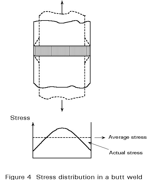
As already pointed out, in weld calculation a uniform stress distribution along the weld length is assumed. In the ultimate state a plastic redistribution of stresses makes this assumption more or less true. In the elastic stage, which is of interest in fatigue design, the stresses are not uniformly distributed, especially not when the filler metal yield point is much higher than that of the parent metal. For example, consider a bar loaded by an axial tensile force as shown in Figure 4. The bar will elongate and, due to the Poisson's ratio effect, its initial width will decrease. This lateral contraction is uniform if the bar is homogeneous. But near the weld line, which has a different yield point, the lateral contraction is less than in the parent metal. This effect causes a varying stress distribution along the weld (Figure 4), in which the tensile stress at the centre is greater than the average stress.
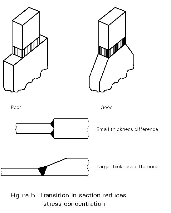
It is good engineering practice to avoid high stress concentrations occurring at sharp re-entrant corners in joints connecting different cross-sections. Avoiding stress concentrations is especially important if the connection will be subject to fatigue loads. To reduce the stress concentration, a gradual transition from one section to the other is recommended (Figure 5). These aspects are also discussed in the lecture on fatigue design and in Lecture 3.5 and Lecture 3.6 concerning fabrication and erection of steel structures.
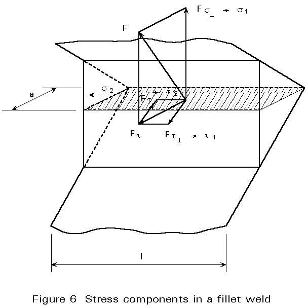
The assumptions adopted for fillet weld calculations according to Eurocode 3 [1] concern mechanical and geometric characteristics. As already pointed out, the mechanical properties of the filler metal shall be compatible with the parent material properties. The throat area of a fillet weld considered in the calculation is shown in Figure 6. This throat area is the product of the throat thickness and the effective length of the weld. Generally, the effective length of a fillet weld is equal to the overall length of the full size fillet, including end returns, if the fillet weld is continuous. For long welds and intermittent welds, the effective length may be reduced.
Fillet welds required to carry loads are normally produced with a throat thickness of at least 4mm. Welds with effective lengths shorter than 40mm or 6 times the throat thickness, whichever is larger, should be ignored for transmission of forces.
The basic method for the design of fillet welds is described here. It is given in Eurocode 3, Annex M [1] as an alternative design method.
The load acting on the fillet weld is resolved into load components parallel and transverse to the longitudinal axis of the weld and normal and transverse to the plan of its throat (see Figure 6). The corresponding stresses are calculated:
s1 = Fs^/al is the normal stress perpendicular to the plane of the throat area.
t1 = Ft^/al is the shear stress in the plane of the throat area, transverse to the weld axis.
t2 = Ft///al is the shear stress in the plane of the throat area, parallel to the weld axis.
s2 is the normal stress parallel to the weld axis.
The normal stress s2 is not considered because the cross-section of the weld is very small and has negligible strength in comparison with the strength of the throat area subjected to the shear stress component t2.
Application of the von Mises criterion to these stress components gives the equivalent stress seq in the throat area of the weld:
seq = Ö[s12 + 3(t12 + t22)] (1)
Eurocode 3, Annex M [1] specifies that the fillet weld will be adequate if both the following conditions are satisfied:
seq £ fu/(bwgMw) (2)
and s1 £ fu/gMw
where
fu is the nominal ultimate tensile strength of the weaker part joined.
g
Mw is the partial safety factor for welds (= 1,25).The value of the correlation factor bw should be taken as follows:
|
EN10025 Steel Grade |
Ultimate tensile strength fu |
Correlation factor bw |
|
S235 S275 S355 |
360 N/mm2 430 N/mm2 510 N/mm2 |
0,8 0,85 0,9 |
For intermediate values of fu the value of bw may be determined by linear interpolation.
Eurocode 3 gives, in the main text, a simplified design formula which does not require determination of the stress components in the weld. The formula is based on the mean stress method which considers the weld strength as being equal to the shear strength, independent of the direction of the force acting on it. Since the weld is weakest in pure shear the mean stress method always gives results on the safe side.
The fillet welds must satisfy:
F/a1 £ fvw = fu/[Ö3.bwgMw](3)
where
F is the external force acting on the weld.
fvw is the design shear strength of the weld.
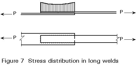
Figure 7 indicates the stress distribution for long welds in a lap joint. The distribution is analogous to that observed in long riveted or bolted joints (see Lectures 11.3). Large stresses occur at the ends of the connection. In the ultimate state, just before failure, the plastic deformation near the ends contributes to a more uniform shear stress in the welds. However, if the connection is long the stress redistribution will not be fully uniform.
Eurocode 3 specifies that the design resistance for a long weld in a lap joint shall be multiplied by a reduction factor blw to allow for the effects of non-uniform stress distribution. If the lap joint is longer than 150a
bLW = 1,2 - ![]() £ 1
£ 1
where
Lj is the overall length of the lap in the direction of the force transfer.
For fillet welds longer than 1,7 metres connecting transverse stiffeners in plated members
bLW = 1,1 - ![]()
but 0,6 £ bLW £ 1,0
where
Lw is the length of the weld (in metres)
The strength of slot and plug welds is calculated with the mean stress method as for fillet welds. In the calculation, the effective area of the slot or plug weld is taken as the area of the slot or hole.
[1] Eurocode 3: "Design of steel structures": ENV 1993-1-1: Part 1: General rules and rules for buildings, CEN, 1992.
[2] Bresler, B., Lim, T. Y., Scalzi, J. B., Design of steel structures, 2nd Edition, 1968.
Informative and well illustrated reference manual covering all aspects of welded design and construction.