ESDEP WG 11
CONNECTION DESIGN: STATIC LOADING
To review the behaviour and the basis for design of local elements in connections.
Lecture 1B.5: Introduction to Design of Industrial Buildings
Lecture 1B.7: Introduction to Design of Multi-Storey Buildings
Lecture 2.3: Engineering Properties of Metals
Lecture 2.4: Steel Grades and Qualities
Lecture 11.1.2: Introduction to Connection Design
Lectures 11.2: Welded Connections
Lectures 11.3: Bolted Connections
Lecture 11.5: Simple Connections for Buildings
Lecture 11.6: Moment Connections for Continuous Framing
Lecture 11.7: Partial Strength Connections for Semi-Continuous Framing
This group of 4 lectures (11.4.1 - 11.4.4) explains how the behaviour of local elements in connections may be analysed so that each component may safely be proportioned to resist the loads it is required to transfer. It therefore develops the basic concepts of force transfer that were presented in general terms in Lecture 11.1.2.
In this first lecture the general principles used in determining the forces for which each component in a connection must be designed are explained. These make use of the fundamental structural concepts of equilibrium, stiffness and deformations to decide how the externally developed loads are shared between the various components. This then leads to the idea of load paths as being the most effective way that applied forces can pass through the connection.
The notation of Eurocode 3 [1] has been adopted.
In Lecture 11.1.2 it was shown in general terms how the structural adequacy of connections can be checked by considering the resistance of the local elements of the connection.
The resistance of a local element is determined on the basis of the resistance of the individual bolts or welds and plates.
The resistance of welds and bolts is covered in Lectures 11.2 and 11.3. In this Lecture 11.4.1 the resistance, stiffness and deformation capacity of a number of components are discussed.
Thus the material of Lectures 11.1, 11.2 and 11.3 is brought together to explain how the individual components in connections can be safely proportioned. This involves both a determination of the forces to which each is subjected and the ways in which, acting in combination, the parts of the connection transfer these forces from the supported member to the supporting member.
Having established the principles, Lectures 11.4.2 - 11.4.4 apply these to the consideration of the transfer of different types of internal forces within connections e.g. direct tension, shear, tension as part of a moment etc., whilst Lectures 11.5 - 11.8 fully develop the ideas to cover the design of particular connection types.
For the determination of the forces on the connection, a static analysis is carried out. Such an analysis includes the determination of the design loads on the structure and the definition of the design basis for the structure.
In defining the design basis, consideration of the structural behaviour of the connections is necessary. Are the connections pinned, or rigid, or semi-rigid? Are they partial strength or full strength connections? More details about the influence of the type of connection on the distribution of forces in the structure are given in Lectures 11.1, 11.5, 11.6, 11.7 and 11.8.
After the determination of the normal forces, shear forces and bending moments on the connections, an internal distribution of forces in the connection is chosen.
The distribution of forces in the connection may be determined in whatever rational way is best, provided that:
a. The assumed internal forces are in equilibrium with the applied forces and moments.
b. Each part of the connection is capable of resisting the forces assumed in the analysis.
c. The deformations imposed by the chosen distribution are within the deformation capacity of the fasteners, welds and other parts of the connection.
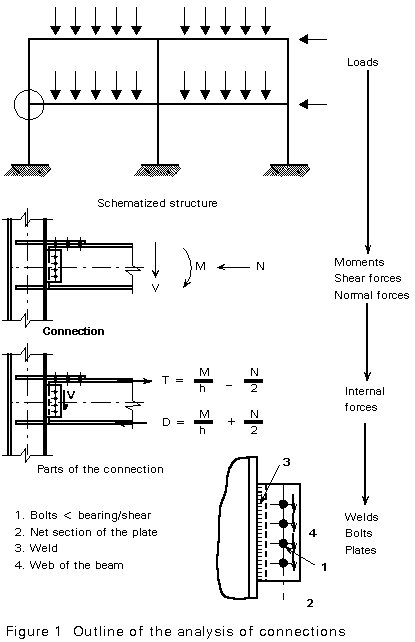
Figure 1 gives an outline of the determination of the load on the individual elements of the connections, and the verification of their resistance.
It is not necessary and it is often not possible to determine the real distribution of forces in the connection. A realistic assumption of internal forces, in equilibrium with the external forces on the connection, is sufficient. In fact selecting this assumption is the most difficult part of the analysis. It requires a sound understanding of the structural behaviour of the connection when it is loaded.
The following rules apply:
a. The distribution of forces in the parts to be connected requires consideration
If, for instance, an I-section loaded in bending and shear, has to be connected, then the shear force is largely concentrated in the web, whilst the flanges carry most of the bending moment. A simple and usually acceptable assumption for the load transfer in the connection is to connect the web for the full shear force and the flanges for the full bending moment, see Figure 1.
b. The stiffness of the various parts in the connection requires consideration
Deformations caused by loads acting in the plane of a plate are much smaller than those produced by loads acting perpendicular to a plate (normal force versus bending moment). In many cases the understanding of the influence of the stiffness ratio on the force distribution can be improved by considering the situation after a small deformation of the connection has occurred. This approach is illustrated in Section 3 by examples.
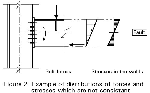
c. The assumed force distribution must be consistent for all parts in the connection
Violations against this rule may occur if a separate calculation is carried out for the different parts in the connection. An example is given in Figure 2. The indicated distribution of forces for the calculation of the bolts is not consistent with the distribution of stresses in the beam assumed to design the welds between the beam and the end plate. Overloading of the welds in the top flange of the beam results.
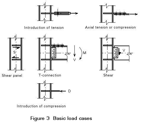
The analysis of the structural behaviour of connections can be carried out by considering a number of basic load cases for local elements. For a T-connection this analysis is demonstrated in Figure 3. The load transfer in nearly every type of connection can be modelled with the five basic load cases. Use of these cases permits a systematic and clear presentation of the calculation methods, despite the wide variety of possible connection types. Eurocode 3 (Chapter 6 and Annex J) follows this approach.
In Lectures 11.4.3 and 11.4.4 calculations for the five basic load cases are presented for a number of connection designs. For each part of the connection, a number of possible failure modes can be identified. They may refer to:
It has to be demonstrated that the weakest link in the connection system (chain) is strong enough to carry the load that acts on it.
The design of the fasteners (welds and bolts) is dealt with in Lectures 11.2 and 11.3. The design of other parts in the connection is dealt with in the present Lectures 11.4.
When distributing normal forces, shear forces and bending moments in the connection, the stiffness differences in the connection must be taken into account. In particular, the deformations due to normal forces in the plane of a plate are much smaller than the deformations due to forces acting perpendicular to it.
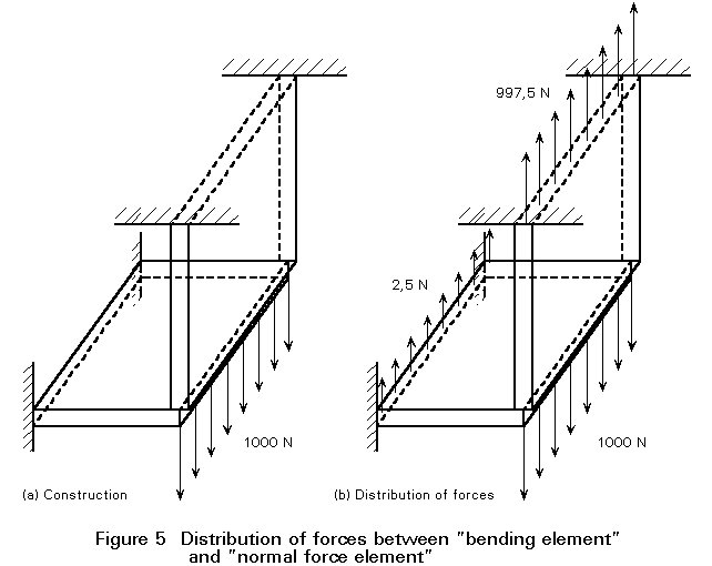
A calculation for the example of Figure 4 gives a good demonstration of this principle. The plate 100 ´ 100 ´ 10 mm, clamped on one side, is loaded with 1000 N perpendicular to the plate surface.
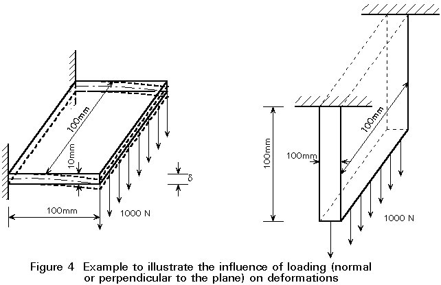
The deflection follows from:
d
= = 0,2 mm
(3-1)
= 0,2 mm
(3-1)
The same plate is loaded with an in-plane tensile force of the same magnitude. The displacement of the end of the plate is now:
D
l =Both plates are now connected, see Figure 5, causing both displacements at the interface to be equal. A load of 1000 N is applied to this structure. The load is carried by both plates, shared in proportion to the stiffness ratio. The plate loaded in tension is 0,2/0,0005 = 400 times stiffer than the plate that is bent. Consequently, nearly the whole load is carried by the plate loaded in tension, see Figure 5b.
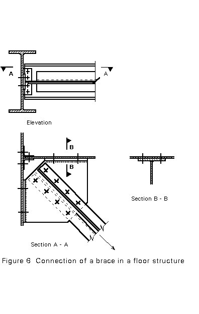
This knowledge is used to determine the distribution of forces for the brace connection shown in Figure 6, e.g. in a floor structure. In this connection many distributions of the forces in the connections, each obeying equilibrium, are possible.
First it is assumed that the force is carried by both connections, whilst the direction stays the same, see Figure 7. For the analysis, the force 0,5 F is resolved as Fs = 0,35 F and Ft = 0,35 F.
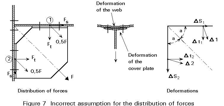
The deformation in the shear direction (Fs) is much smaller than the deformation in the tensile direction (Ft). The result is that the deformation D1 at point (1) is very different from the deformation D2 at point (2). The deformations D1 and D2 cannot be accommodated by the gusset plate!
This means that the deformation at point (1) caused by Fs (DS1) must be the same as the deformation at point (2) caused by Ft (DS2).
Therefore, Fs is much larger than Ft. The distribution of forces in Figure 7 is incorrect.
The correct distribution is indicated in Figure 8. The force F effectively causes only shear in the bolt groups (1) and (2). The tension load in the bolts can be ignored.
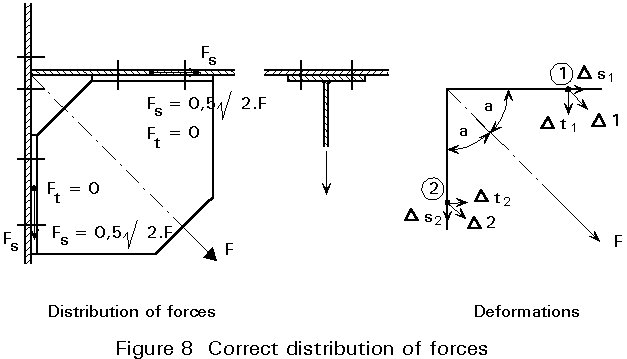
Conclusion: If large differences in the stiffness between two possible types of load transfer exist, then ignore the load transfer that gives the larger deformations (bending deformation of the plate), and assume that all load is transferred in the way that gives the smaller deformations (deformation in the plane of the plate).
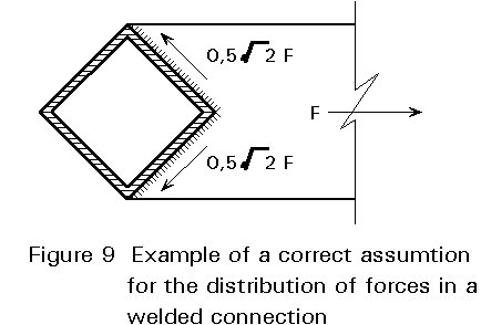
This approach also applies to welded structures, e.g. see Figure 9 which illustrates the connection of a plate to a square hollow section. The assumed force distribution where the welds are only loaded in shear is correct.
The stiffness ratio in the connection may influence the assumption for the calculation of the bending moments. An example is given in Figure 10. In the connection in Figure 10a, the rotation of the bolted connection is larger than the rotation of the plate which is welded in the plane of the web of the column. Therefore, the hinge for the calculation of moments is assumed to be the bolt row. The bolts are loaded by a shear force V. The welds must be designed for a shear force V and a bending moment V.e.
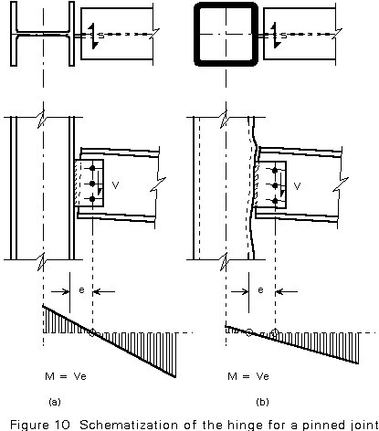
In the connection in Figure 10b, the plate is welded to the non-rigid wall of the square hollow section. Here the more logical place for the hinge is this wall. The weld is now only loaded in shear and consequently, the bolt row is loaded in shear (V) and bending (V.e).
a. Free centre of rotation
The plates in Figure 11 are connected by bolts arranged in an arbitrary pattern. The connection is loaded by a bending moment M. The plates are assumed to be rigid, compared with the stiffness of the fasteners. Therefore, the rotation q between the plates is the result of the deformation of the fasteners. The plates rotate around the centre of rotation.
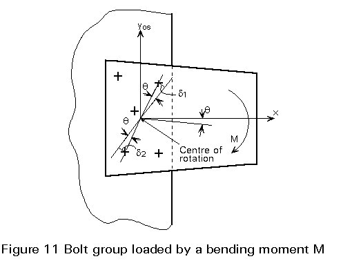
In the case of small deformations of the fasteners, a linear relation between the bolt forces Ri and the displacements di may be assumed, giving bolt forces Fi proportional to the distance ri to the centre of rotation and the rotation q, see Figure 12.
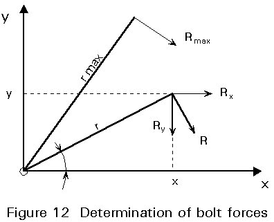
di = ri q (3-3)
Ri = (ri/rmax)Rmax (3-4)
Rxi = (yi/ri)Ri = (yi/rmax)Rmax (3-5)
Ryi = (xi/ri)Ri = (xi/rmax)Rmax (3-6)
If the load on the connection is a pure bending moment, equilibrium requires that the resultant forces in the x and y directions must be zero:
SRxi = Rmax/rmax Syi = 0 ® Syi = 0 (3-7)
SRyi = Rmax/ rmax Sxi = 0 ® Syi = 0 (3-8)
The centre of rotation is therefore located at the centroid of the bolt group.
M = Sri . Ri = S(Rmax/ rmax) . Rmax = (Rmax/rmax) Sri2 (3-9)
Rmax = ![]() (3-10)
(3-10)
This situation with the centre of rotation at the centroid of the bolt group is called "free centre of rotation".
If an eccentric force acts on a bolt group with free centre of rotation, the following analysis can be carried out, see Figure 13.
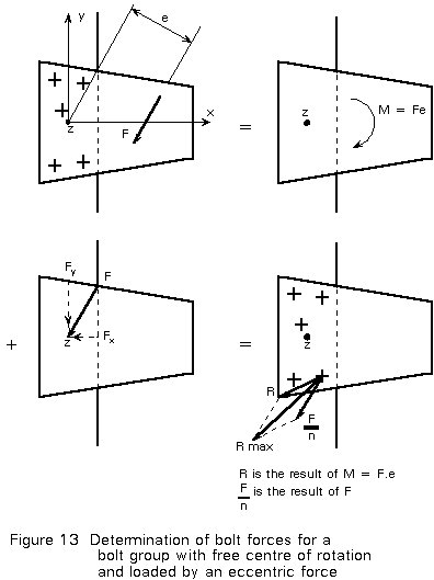
The eccentric force F can be replaced by a bending moment M = F . e and a force F through the centre of rotation. The loads on the bolts are the summation of the loads caused by M (as explained above) and the loads caused by F. For n bolts, each bolt carries F/n. The resultant force on each bolt can be determined by resolving the forces caused by M and F in the x-direction and in the y-direction:
Fx = FxM + FxF (3-11)
Fy = FyM + FyF (3-12)
R = ![]() (3-13)
(3-13)
For an arbitrary bolt pattern it is not easy to determine in advance which bolt is the most heavily loaded. Several bolts have therefore to be checked. In practice, however, the bolt pattern is usually regular and the more severely loaded bolts are readily identified.
b. Forced centre of rotation
In an end plate connection of the type shown in Figure 14, there is an important difference between the stiffness of the tension zone and the compression zone.
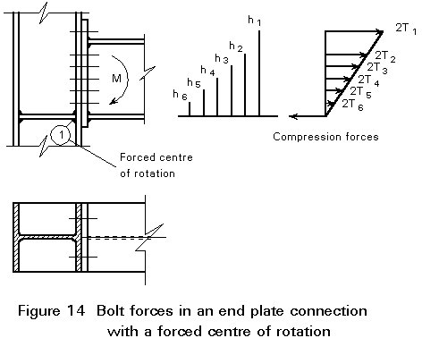
In the compression zone, the compression force is transmitted directly from the flange of the beam to the web of the column. The deformations in the compression zone are very small compared to the deformations in the tension zone, where bending of the end plate and bending of the column flange occurs.
Because of this difference in the stiffness, the centre of rotation is effectively located at point (1) in Figure 14. Sometimes, to be more conservative, the centre of rotation is taken as the lowest bolt row.
If the end plate is thick and therefore stiff, then the centre of rotation may also be assumed at the lower end of the plate.
The above situation, where the centre of rotation is not in the centre of the bolt group, is called a connection with a "forced centre of rotation".
Assuming that the stiffness at each bolt row is the same, the forces in the bolt rows are directly proportional to their distance from the centre of rotation. With the centre of rotation at point (1), the following analysis can be carried out:
h1 2T1 + h2 2T2 + h3 2T3 + h4 2T4 + h5 2T5 + h6 2T6 = M (3-14)
With equal bolt sizes:
2T2 = 2T1 ![]()
2T3 = 2T1 ![]()
2T4 = 2T1 ![]()
2T5 = 2T1 ![]()
From these equations, the bolt force T1 in the most heavily loaded bolt can be determined:
![]() (3-15)
(3-15)
In reality, the stiffness of the bolt rows may differ considerably, e.g. the extended part of the end plate above the beam's top flange in Figure 15 is less stiff than the part below the top flange where the web of the beam has a stiffening effect. As a result, bolt row number 2 will transmit a higher load than bolt row number 1.
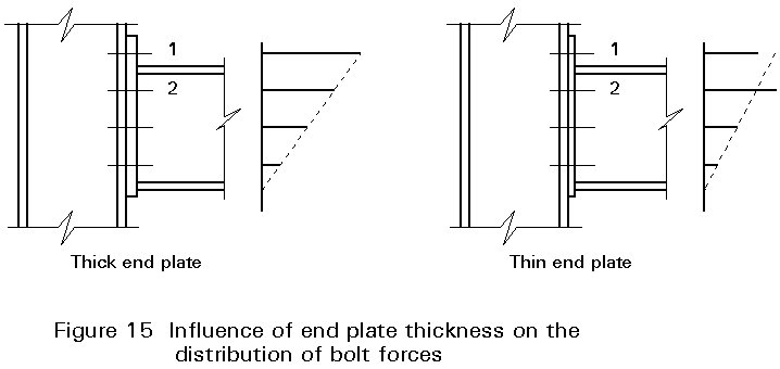
For thin end plates the differences in the stiffness of different bolt rows is more pronounced and the distribution of forces in the bolt rows is more variable.
With "normal" dimensions of the end plate, it is reasonable to assume that the tension force in the top flange of the beam is equally distributed between bolt rows 1 and 2.
If an end plate connection is loaded by a combination of bending moment M and a tensile force FH, the situation with a forced centre of rotation may occur, but also a free centre of rotation is possible. This depends on the magnitude of FH, see Figure 16.
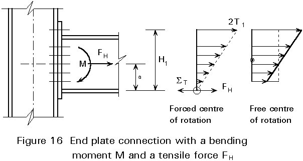
If the centre of rotation is forced (FH is small), then FH is transferred through the rigid point (1). The bending moment about (1) is:
M1 = M + FH . a = ![]() Shi2
(3-16)
Shi2
(3-16)
where
a is the distance between the centre line of the beam and the compression point (1).
From the condition of horizontal equilibrium it follows that:
D = ![]() S hi - FH (3-17)
S hi - FH (3-17)
If:
FH = ![]() S hi (3-18)
S hi (3-18)
then D = 0. With D < 0, there is no longer a forced centre of rotation. From Equations (3-16) and (3-17) it follows that if:
a + ![]() (3-19)
(3-19)
there is a forced centre of rotation, and if:
a + ![]() (3-20)
(3-20)
there is a free centre of rotation.
i. Internal forces must be in equilibrium with the external applied forces and moments.
ii. Each part of the connection must be capable of safely resisting the forces in it assumed by the analysis.
iii. The deformations required by the assumed internal force distribution must be within the deformation capabilities of the component parts.
[1] Eurocode 3: "Design of Steel Structures" ENV 1993-1-1: Part 1.1, General rules and rules for buildings, CEN, 1992.