ESDEP WG 11:
CONNECTION DESIGN: STATIC LOADING
To provide an initial introduction to the various aspects of connection design in simple steel construction.
Lecture 1B.5.1: Introduction to Design of Simple Industrial Buildings
Lectures 1B.7: Introduction to Design of Multi-Storey Buildings
Lecture 3.5: Fabrication/Erection of Buildings
Lecture 11.1.1: Connections in Buildings
Lecture 11.1.2: Introduction to Connection Design
Lectures 11.2: Welded Connections
Lectures 11.3: Bolted Connections
Lectures 11.4: Analysis of Connections
Lecture 11.6: Moment Connections for Continuous Framing
Lecture 11.7: Partial Strength Connections for Semi-Continuous Framing
The relation between the selection of the frame model and the connection design is first discussed. The various forms of connections in simple buildings are identified for both the framework and the bracing system, and the main design criteria and checking procedures are presented. Reference is also made to the economic implications concerning fabrication and erection. Detailed aspects of behaviour and design are referred back to earlier lectures in the group.
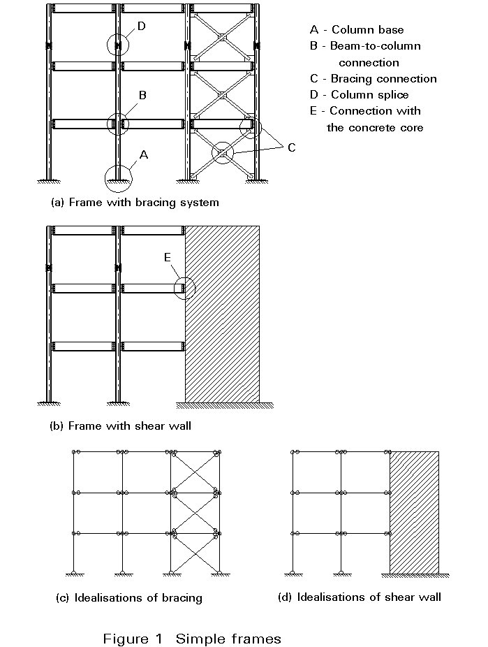
Simple connections are defined as joints between members that have not been designed with the intention that they transmit significant moments. Their purpose is to transfer load from the supported member into the supporting member in such a way that essentially only direct forces are involved, e.g. vertical shear in a beam to column or beam to beam connection, axial tension or compression in a lattice girder chord splice, column base or column splice connection. They may, therefore, only be used in situations where sufficient bracing is present that, when the joints are assumed to function as pins, adequate overall structural resistance is present. Popular arrangements include lattice girders and bracing systems or connections between beams and columns in rectangular frames in which lateral loadings are resisted by stiff systems of shear walls, cores or braced bays.
Figures 1a and 1b illustrate multistorey frames in which simple connections may be used for each of the 6 different requirements A-E listed alongside Figure 1a. Thus the structural idealisations suitable for determining the distribution of member forces will be as shown in Figure 1c and 1d, with all lateral loading being resisted by the bracing or shear wall. When considering the design of the frame to withstand gravity loading, the assumption of pin connections makes the overall structural analysis particularly straightforward, since loads can be traced from floors into beams into columns and eventually into the foundations using a simple statical process.
Simple joints also lead to easier fabrication and erection and as explained in Lecture 11.1.1 are, therefore, likely to produce the most cost-effective steel frames. Taking the example of a beam to column connection, the simple joint must:
Thus, in terms of the classification system introduced in Lecture 11.1.2., the connection should function as "nominally pinned" for both moment capacity and rotational stiffness and the only form of load transfer required will be the vertical shear illustrated in Figs. 9(2) and 11 of that Lecture.
Simple connections will normally be either fully bolted, e.g. the arrangements using angle cleats of Fig. 10 of Lecture 11.1.1, or will involve a combination of shop welding and site bolting, e.g. the fin plate and end plate arrangements of the same Figure. Except for connections subject to vibration, e.g. in foundations for moving machinery or in crane support structures, untorqued bolts in clearance holes should be used.
This lecture discusses the structural design of several examples of each of the 6 connection arrangements listed in Figure 1. In doing this it makes use of basic material on weld strength and bolt strength presented in Lectures 11.2 and 11.3 respectively, as well as the approach to the analysis of connections given in Lecture 11.4.
Floor decks in buildings are usually supported by means of grids of secondary beams and main girders simply connected to each other.
Some typical connections are illustrated in Figure 2. Types A and C, which make use of web cleats bolted to both the girder and the beam, are the most common forms. Type B with the cleats bolted to the girder and welded to the beam, and types D and E where a flush end plate is adopted, may cause lack-of-fit problems during erection due to the dimensional tolerances. Connection types D and E possess some predictable stiffness and strength, but their consequent partial continuity is usually neglected in design.
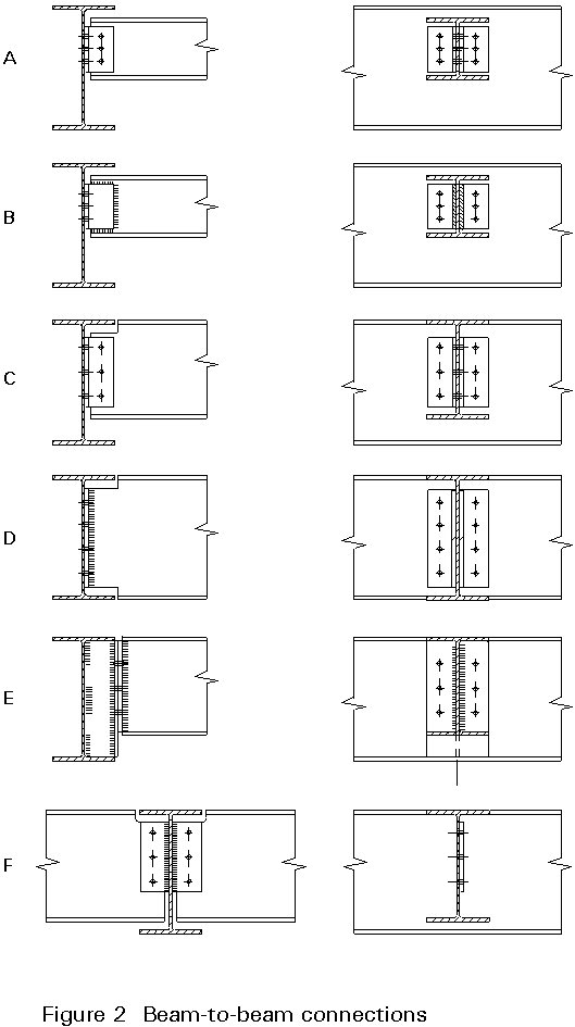
As shown in types C and D, the beam end may be coped removing part of one or both flanges, when the beam and girder flanges meet at the same level. The beam is thus locally weakened. The appropriate checks must be made as discussed below. Nevertheless, this solution is less expensive than type E, which requires that a tee stiffener is welded to the girder.
As a variant to A the web angles may be replaced by a fin plate, as shown in Type F, a single plate which is shop welded to the primary beam and site bolted to the secondary beam. A fin plate connection is particularly simple to both fabricate and erect, but it requires careful design if it is to function as a notional pin [1]. In particular, there is a need to decide where the "hinge" is located as explained in Section 3 of Lecture 11.6.
For web cleated connections, it is good practice to place the angles as close as possible to the upper flange of the girder in order to minimise cracking of the concrete floor slab due to the beam rotation.
Bolts and welds in connections should be able to resist the beam reaction and any relevant moment due to the eccentricity of the force to the centerline of the connecting components as explained in Section 2 of Lecture 11.4.3.
When a beam is coped, as in connection type C, it should be verified that no failure may occur at the section that has been weakened (block shear) as explained in Section 2 of Lecture 11.4.3.
Several forms of simple beam-to-column connections are illustrated in Figure 3.

Type A, which is shown as fully bolted, may also be configured by welding the cleats to the beam end. For lightly loaded beams, a single sided cleat may be used but the additional eccentricities must then be allowed for when checking bolt strength, etc.
The finplate Type B requires the same form of attention when deciding on the design model as discussed in the previous section where its use in beam to beam situations was discussed. It is one of the few arrangements obviously suitable for use with SHS (either RHS or CHS) columns as no bolting to the column is necessary.
Both types A and B provide some allowance for tolerance (through the clearance in the beam web holes) on member length. Type B permits beams to be lifted in from one side.
Types C and D require a more strict control of beam length and of squareness of the cross-section at the end of the beam. The flush end plate scheme of type D is sometimes preferred to the part depth end plate (type C) in order to reduce the chances of damage during transportation. Partial depth endplates should not normally be less than about 0.6 times the beam depth or the end torsional restraint to the beam may be reduced. Figure 4 illustrates how flexibility and rotation capacity is provided. Depending on the details, the connection behaviour of type D could change from a notational pin; it may be more appropriate to acknowledge this semi-rigid behaviour (see Lecture 11.7). This may be avoided by keeping the endplate thickness down to a maximum of 8-10 mm and making the bolt cross-centres as large as is practical so as to ensure adequate flexibility and rotation capacity.

As for beam-to-beam connections, the bolts and the welds should be able to resist the beam reactions and the relevant moment due to the eccentricity of the force to the centreline of the connecting material as explained in Lecture 11.4.3. Since this eccentricity is relatively small the column bending moment for such a connection is much smaller than from a moment connection as discussed in Lecture 11.6.
Since the general approach to the design of all forms of simple connections is essentially the same, it will be sufficient to consider only one type in some detail. Figure 5 illustrates the 6 possible failure modes for a finplate connection; the load carrying capacity for each must be calculated and the lowest value compared with the design requirements. Methods for doing this have already been presented in Lectures 11.4. It is also necessary to ensure - usually by means of appropriate detailing - that the connection will function in the manner intended, i.e. will not be too stiff and will possess adequate rotation capacity. This may be achieved by:
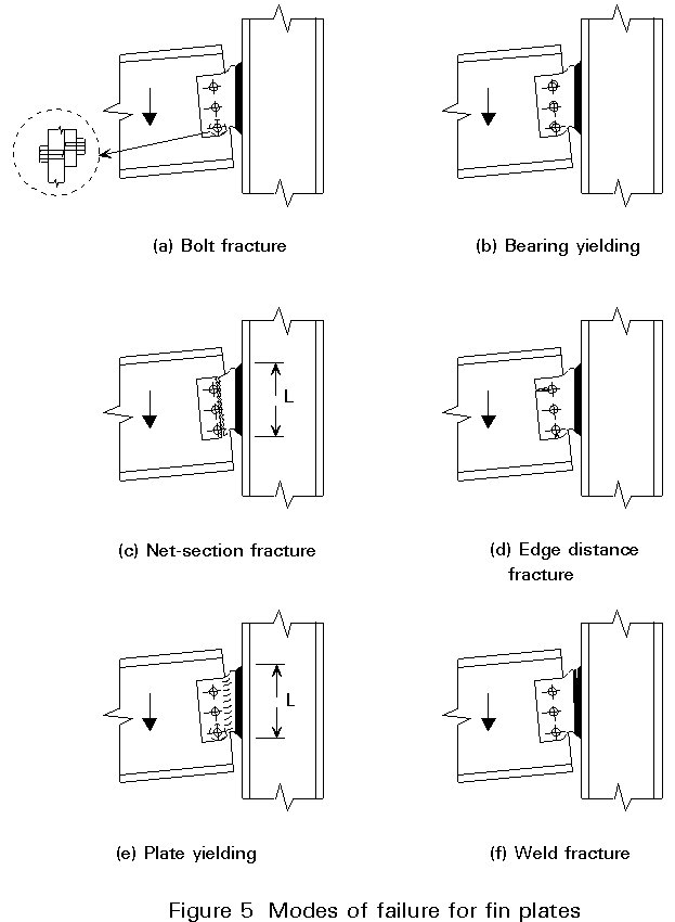
Bearing of the bolts in either the finplate or the beam web is usually arranged to form the governing condition. When performing the structural checks it is necessary to be consistent in the assumption of the location of the line of shear transfer, i.e. the "hinge" line. One approach (1) that removes the need for a decision is to design both the bolt group and the welds for the combination of shear and eccentricity moment. Alternatively, the location can be chosen as the bolt group for the stiff support arrangement illustrated in Figure 5 or the weld if the support is more flexible as would be the case, for example, if a RHS column were used (due to bending of the column face as a plate).
In simple frames columns are predominantly stressed in compression. In theory no splice connection is required, since the compression force is transmittable by direct bearing. Due to the presence of geometric imperfections (lack of straightness of the column) as well as of unavoidable eccentricities, and to the fact that even carefully machined surfaces will never assure full contact, connections have to be provided. They should be designed to resist the internal forces (other than compression) determined in the column at the point where they are located.
Even when the column is subject to simple compression, and full contact in bearing is assumed, codes specify stiffness and strength requirements to be fulfilled. Eurocode 3 prescribes that the splice should provide continuity of flexural stiffness about both axes, and should be able to carry a force, acting at the abutting ends in any direction perpendicular to the axis of the member, not less than 2,5% of the compression.
The location of the splice should be selected so that any adverse effect on column stability is avoided, i.e. the distance of the connection from the floor level should be kept as low as possible. A limit of 1/5th of the storey height is usually accepted. If this requirement cannot be fulfilled, account should be taken of the (second order) moment induced by member imperfections.
More significant bending resistance may be required in splices when columns are subject to primary moments, as in a frame model assuming hinges at, or outside, the column outer face. In addition, in columns acting as chords of cantilever bracing trusses, tensile forces may arise (uplift) in some loading conditions, which must be transmitted by splices.
Typical column splices suitable for use in simply designed frames are shown in Figure 6. They are of two basic types: A, B and C all transmit the whole of the force through the cover plates, whilst D-G rely on direct bearing.
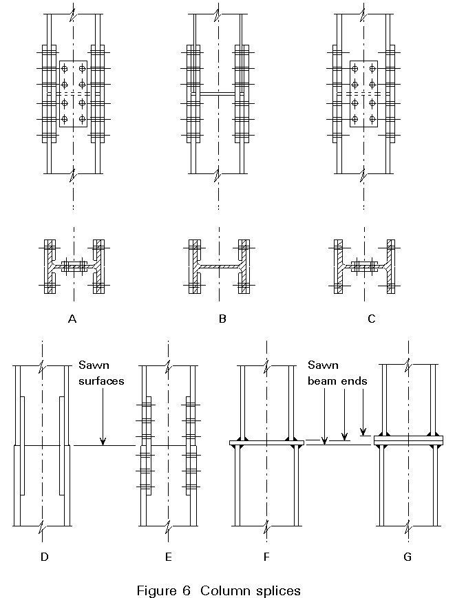
When a bolted solution is adopted (types A, B and C), both flanges and the web are usually connected. Type A uses a double cover plate, whilst type C uses single cover plates for the flanges. These may be positioned on the outside faces of the flanges so as to reduce the plan area occupied by the splice. Forces are distributed among the connecting plates in proportion to the stress resultant in the cross-sectional elements, e.g. for simple compression in proportion to the areas of the flanges and of the web. Differences in column flange thickness may be accommodated by the use of packs.
When the surfaces of the end cross-sections of the two column shapes are sawn and considered to be flat, and squareness between these surfaces and the member axis is guaranteed, the axial force may be assumed to be transmitted by bearing. Fillet welds (type D) or light cover plates (type E) are provided to resist possible secondary shear force and bending moment when the upper and lower columns differ in serial size. A plate may be interposed, and welded to both column sections as in connection type F, or, alternatively, two welded plates bolted to each other may be used (type G). Plates are flattened by presses in the range of thicknesses up to 50m, and machined by planing for thicknesses greater than 100mm. For intermediate thicknesses either working process may be selected.
Where there is a significant variation of cross-sectional dimensions in the arrangement of type F, the plate(s) must be checked for bending resistance. A possible conservative model assumes the plate is a cantilever of breadth equal to the width of, and clamped to, the upper column flange. The axial force, which is transmitted between the corresponding column flanges, is applied as an external load at the mean plane of the flange of the lower column.
Full details of this approach are presented in ref. 2, from which it is clear that if plate thicknesses are to remain reasonable, then only moderate offsets of the order of the column flange thickness are possible. For larger differences in column size, a short vertical stiffener may be located directly below the flange(s) of the upper column to directly assist in transferring the locally high force.
Connections within the bracing system or between the bracing system and the main framing have to transfer forces between a number of differently oriented members. Since the triangulated bracing arrangement will have been designed on the basis that each member carries only axial forces (apart from any relatively small bending effects due to non-coincidence of centroidal axes), the design requirement for the bracing connections is essentially the transfer of direct forces between a number of differently oriented members.
Two basic arrangements are illustrated in Figure 7: Type A attaches the bracing to the main framing, Type B is an internal bracing connection. Types C and D combine both functions by making the beams part of the bracing system. Details of the design considerations and the calculations necessary to effect these have already been provided in Section 1.3 of Lecture 11.4.3.

A column base connection always consists of a plate welded to the foot of the column and bolted down to the foundations. A second, usually rather thicker, steel plate is normally incorporated into the top of the foundation, as illustrated in Figure 8. It helps both to locate the foot of the column accurately and in spreading the load into the weaker (concrete or masonry) foundation material.
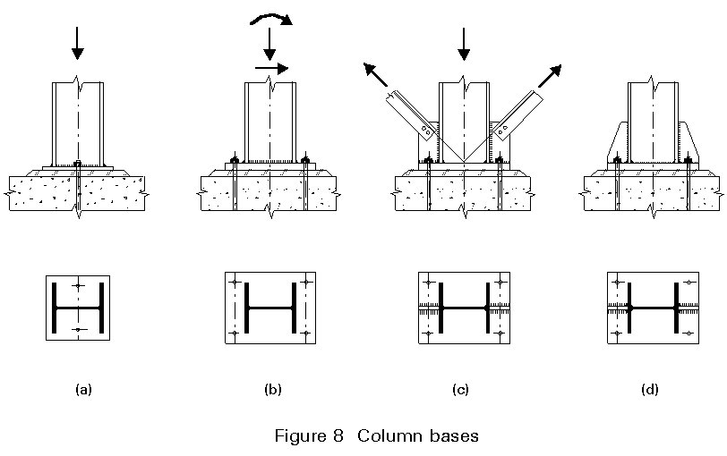
Baseplate connections in simple construction are generally modelled as pins, and designed to transfer either concentric force (compression or tension) or a combination of axial and shear force (usually when the column is part of the bracing system (Figure 8c)). In some instances they may, however, be designed to transmit also bending moments due to moderate load eccentricity, or for erection stability.
The plate is always attached to the column by means of fillet welds. However, if the column carries only compression loads, direct bearing may be assumed, provided that the contact surfaces are machined or can be considered to be flat. No verification of the welds is then required. Machining may be omitted if loads are relatively small.
Where there are moderate tension forces or no net tension the holding down bolts are usually cast into the foundation (Figure 9). They anchor the baseplate by bonding (Figure 9a), by bonding and bearing (Figure 9 b, c), or by bearing (Figure 9d).
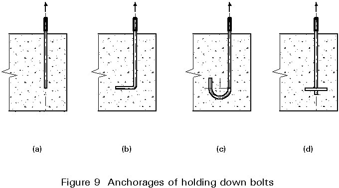
When tensile forces are significant, it is necessary to provide appropriate anchorage to the bolts. For example threaded bolts may be used in conjunction with channel sections embedded in the concrete.
In tension connections the baseplate thickness is often dictated by the bending moments produced by the holding down bolts. The bending moments may require the use of stiffeners (Figures 8c and 8d). Such an arrangement significantly increases the fabrication content and therefore the cost of the column base as compared with the "simple" case.
In high-rise buildings it may be convenient to combine the steel structure resisting gravity loads with a concrete core resisting horizontal forces.
Attaching the steel frame to a concrete core is mainly a practical problem, since the two systems are built with dimensional tolerances of a different order of magnitude. Special care should be taken to account for the relative sequence of erection of the concrete and steel system, the method of construction of the core (on which concrete tolerances also depend), as well as the feasibility of compensating for misalignments.
The connection should be able to transfer to the core vertical forces, V, due to loads applied to the beam, and horizontal forces, H, due to wind and frame geometrical imperfections (lack of verticality). Some connection types are illustrated in Figure 10. It is important to stress that the details in the concrete wall must be suitably designed to disperse connection forces safely. In particular the details are especially important when deep beams are required to transmit high vertical loads.
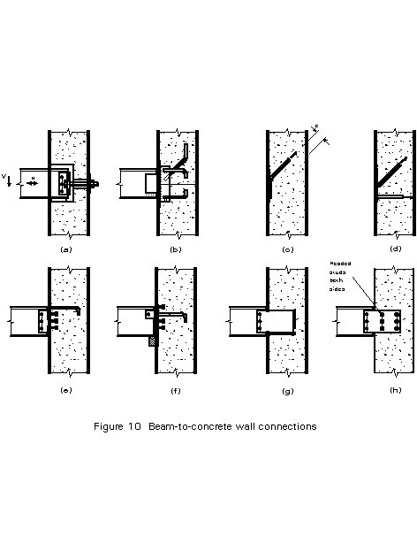
The type shown in Figure 10a, with pockets in the wall, is convenient for ease of adjustment, but complex in terms of core erection. Types illustrated in Figures 10b to 10h where part of the connection is encased in the core wall during concrete pouring, may be preferable.
The steel plate may be flush with the wall surface, as in types b-f, or extended outwards as in types g and h. In the first case, which is usually the more convenient because the steel plate can be supported on the inside face of the formwork, a single web plate is welded on site to which the steel beam is then attached. In the latter case the beam can be connected directly to the encased plate. Reinforcing bars (rebars) and/or headed studs can be used in order to transmit both components of the beam action. Full penetration welds are preferred when the rebars are connected directly to the flush plate (Figure 10d), so that eccentricity of the force with respect to the weldment is avoided (Figure10c).
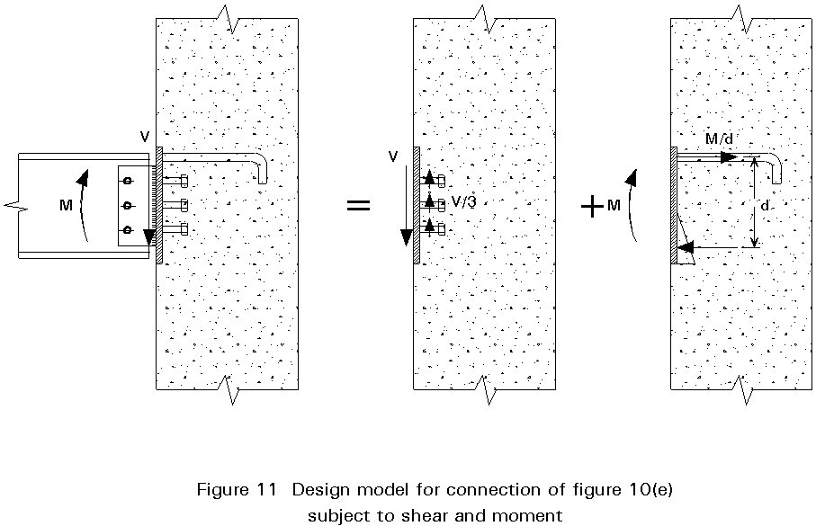
Checking of the various components within the connection should be conducted in a consistent manner, ensuring that the principles of connection design, e.g. the assumed distribution of forces satisfies equilibrium, are observed. As an illustration of this, consider the structural requirements for the arrangement of Figure 10h. Assuming that the shear transfer plane, ie. the "hinge" location of the simple connection, is the mid-plane of the wall, then the set of headed studs must resist only shear. Alternatively, if the "hinge" is assumed as the wall face, then the studs should be designed to resist a combination of shear and moment. This general requirement for a consistent approach to modelling the force transfers is further explained in Figure 11, which details the load transfer for the arrangement of case 10e. The shear force V is assumed to be resisted entirely by the shear studs, whilst the moment M is carried by a couple consisting of tension in the upper rebars and compression transmitted by contact stresses between the concrete and the steel plate. Whichever arrangement is adopted, however, the main requirement is to ensure a proper dispersion of forces into the core wall.
[1]. BCSA/SCI "Joints in Simple Construction", Volume 1: Design
Methods (2nd edition) 1993 pp 81/94
Provides an explanation of basic behaviour, suggested proportions for the key components and detailed rules for checking the structural adequacy of beam to beam, beam to column, column splice and column base connections.
[2] Ballio, G. and Mazzolani, F.M., "Theory and design of steel structures", Chapman and Hall, London 1983.
Comprehensive text on theory and design of steel structures. Deals extensively with connections.
General problems of welding and bolting as well as detailing practice are extensively covered. Basic design guidance and examples of different types of structures ranging from buildings to towers and bridges are also given.
This book presents a wide range of practical solutions for connections in steel and composite buildings. It is available in four different European languages (French, English, Dutch and Italian).
Describes a variety of practical connections between steel, concrete and masonry, including column bases and connections to existing concrete and masonry for refurbishment projects.
Presents design models and resistance tables for the main connection types.
Informative and well illustrated reference manual covering all aspects of welded design and construction.
Chapter 6 covers the design of fasteners, and of connection components. Appendices J and L deal with the design of beam-to-column and column base connections respectively.
Gives a comprehensive appraisal of the behaviour of bolted joints, and reviews in detail methods for design analysis.