ESDEP WG 1B
STEEL CONSTRUCTION:
INTRODUCTION TO DESIGN
To describe the reasons for the use of steel and to present common forms of structure for industrial buildings.
None.
Lecture 1A.1: European Construction Industry
Lecture 1B.2.1: Design Philosophies
Lecture 1B.3: Background to Loadings
Lecture 7.12: Trusses and Lattice Girders
Lecture 14.1.1: Single Storey Buildings: Introduction and Primary Structure
Lecture 14.1.2: Single Storey Buildings: Envelope and Secondary Structure
Lecture 14.2: Analysis of Portal Frames: Introduction and Elastic Analysis
Lecture 14.3: Analysis of Portal Frames: Plastic Analysis
The reasons for the wide use of steel for industrial buildings are discussed. The advantages of steel include its high strength-to-weight ratio, speed of erection and ease of extension. Steel is used not only for members but also for cladding.
Common types of structure are described. These types include portal frame, lattice girder and truss construction. It is shown that overall stability is easily achieved. The wide variety of sections used in industrial buildings is presented. Possible approaches to global analysis are identified.
A wide variety of building types exists, ranging from major structures, such as power stations and process plants, to small manufacturing units for high quality goods.
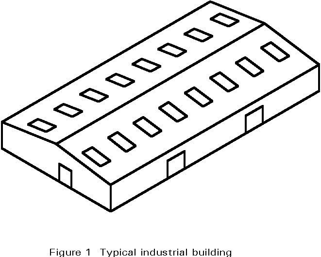
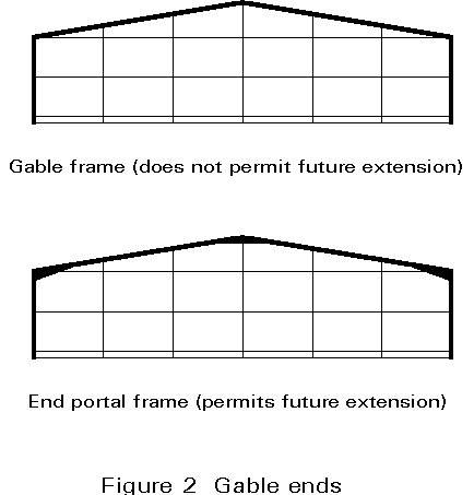
The most common type is the simple rectangular structure (Figure 1), typically single-storey, which provides a weatherproof and environmentally comfortable space for carrying out manufacturing or for storage. First cost is always an overriding consideration, but within a reasonable budget a building of good appearance with moderate maintenance requirements can be achieved. While ease of extension and flexibility are desirable, first cost usually limits the provisions which can be usefully included in the design for these potential requirements. Although savings in the cost of specific future modifications can be achieved by suitable provisions, for example by avoiding the use of special gable frames (Figure 2), changes in manufacturing processes or building use may vary the modifications required.
When, for reasons of prestige, the budget is more liberal, a complex plan shape or unusual structural arrangement may provide a building of architectural significance.
While many features are common to all industrial buildings, this lecture deals mainly with single-storey buildings of straightforward construction and shape.
Compared to other materials, particularly reinforced or prestressed concrete, steel has major advantages. Its high strength-to-weight ratio and its high tensile and compressive strength enable steel buildings to be of relatively light construction. Steel is therefore the most suitable material for long-span roofs, where self-weight is of prime importance. Steel buildings can also be modified for extension or change of use due to the ease with which steel sections can be connected to existing work.
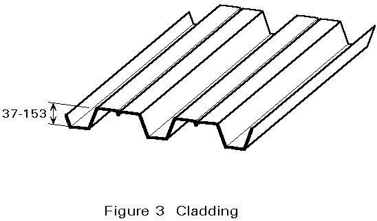
Not only is steel a versatile material for the structure of a building, but a wide variety of cladding has been devised utilising the strength developed by folding thin sheets into profiled form (Figure 3). Insulated cladding systems with special coatings are now widely used for roofing and sidewall cladding. They have good appearance and durability, and are capable of being speedily fixed into position.
The structure of a steel building, especially of an industrial building, is quickly erected and clad, providing a weatherproof envelope which enables the floor and installation of services and internal finishes to proceed at an early stage. Since the construction schedule is always tied to the earliest handover date fixed by production planning, time saved in construction is usually very valuable.
In a dry closed environment steel does not rust, and protection against corrosion is needed only for the erection period. For other environments protection systems are available, which, depending on cost and suitable maintenance, prevent corrosion adequately.
Single storey industrial buildings are usually exempt from structural fire protection requirements. Spread of fire beyond the boundary of the building must not occur as a result of collapse of the structure. This requirement can be met by the provision of fire walls and through the restraint which arises in practice between the bases and the columns which they support.
A prospective owner may have a fully detailed design brief derived from the construction of industrial plants elsewhere. More usually the owner is assisted in the choice of a suitable building by the completion of a detailed list of requirements so that a design brief can be prepared. Initial options in respect of preferred location, site acquisition and environmental needs must first be decided. Then main dimensions, process operation, plant layout, foundation needs, handling systems, daylighting, environmental control, service routes, staffing level and access all require definition.
The preliminary selection must be made between a building specially designed for the owner, a new factory largely built of standard structural components, or the adaptation of an existing building. The latter may be either an advance unit built as a speculative development, or a unit which has been vacated.
The location of internal columns and the internal headroom are always important, and consideration of these requirements alone may determine the choice. The advantage of freedom to plan the building to suit requirements closely and allow for future development is very valuable. However, unless there are exceptional reasons such as permanence of specific use, it is unwise to design an industrial building exclusively for a single process, since special features appropriate to the process may make redevelopment difficult.
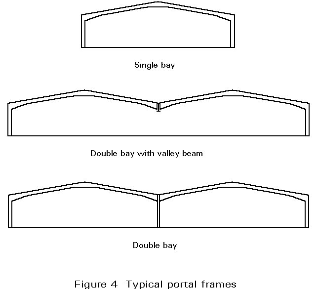
Because of its economy, the most widely used building shape is the pin-based single or multi-bay pitched roof portal frame, typically of 20-30m span at 6m centres (Figure 4). Hot-rolled I, welded or cold-formed sections are usually used for the members.
During recent years an increasing use of welded sections has occurred. This increase is the result of progress achieved in making welding automatic and the ability to adapt the cross-section to the internal forces.
Since internal columns sterilise an appreciable space around them, their spacing may be increased by using spine I-beams to support the portal rafters. For this type of roof the cladding is usually insulated metal decking, which may also be used for the upper sidewalls. Daylight is provided by profiled translucent sheeting in the roof.
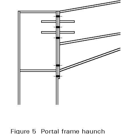
When hot-rolled sections are used, haunches (Figure 5) are usually provided at the eaves and the ridge. These haunches deepen the overall section, thereby reducing bolt forces. By extending the haunched regions along the rafter the frame is also strengthened and stiffened.
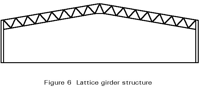
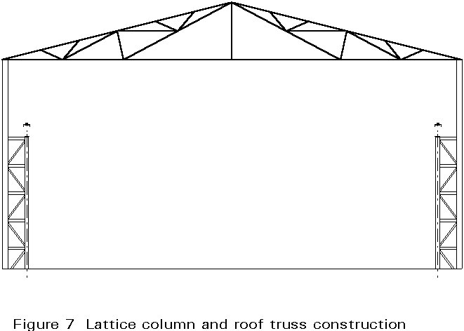
Lattice girders (Figure 6) are lighter than portal frame rafters for wider spans, but the additional workmanship increases fabrication costs. Based on structural requirements alone, lattice systems are likely to be cost-effective for spans above 20m. Roof trusses may also be used for structures which support heavy cranes (Figure 7).
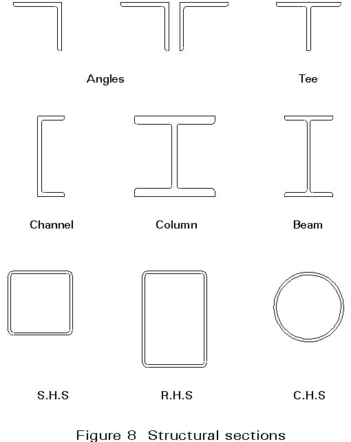
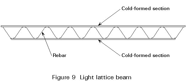
A wide variety of structural sections may be used for lattice girders and roof trusses, including single angles, angles back- to-back, tees, H-sections or hollow sections (Figure 8). For light loading, cold-formed sections may be used as booms, with reinforcing bars as the web members (Figure 9).
The disadvantages of multi-bay pitched roofs are that internal gutters and rainwater disposal are required, which are a possible source of leaks, and access to plant mounted externally on the roof is difficult.
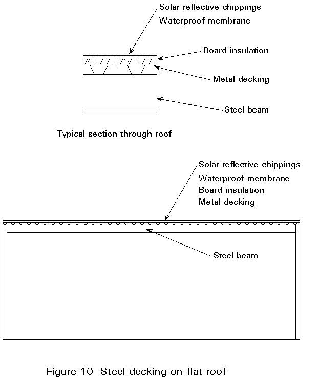
The most versatile roof shape is the nominally flat roof, covered with an insulated membrane on metal decking (Figure 10). This shape allows wide freedom in plan form, and eliminates the need for internal gutters, although some internal rainwater disposal may be necessary if the extent of the roof is large. The mounting and weather protection of external plant on the roof is simply achieved, and access can readily be provided.
Flat roofs can be supported by rolled or cold-formed purlins on main I-beams or lattice girders. For smaller structures the deck may span directly from one frame to another, without the need for purlins.
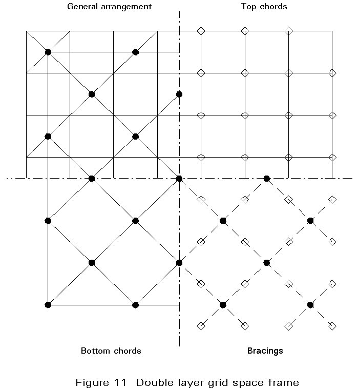
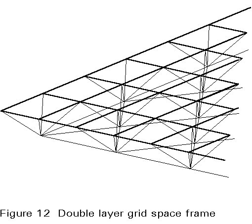
When services are extensive and there are many external plant units on the roof, castellated beams or double-layer grid space frames (Figures 11 and 12) can be very suitable for flat roofs. The two-way grid distributes local loads better than any other structural form. The support for the roof deck is provided directly by the top layer and support for the services by the bottom layer of the grid. Castellated beams have a much higher moment of resistance than I-beams.
The provision of daylighting in flat roofs is expensive, since either dome or monitor lights must be used. Flat roofs are most common for industries where daylighting requirements are minimal.
It is essential to ascertain the loads applied to the structure and to determine the load paths from the cladding to the purlins and side rails, through the main frames to the foundations. The loads may arise from dead load, wind load and snow load, and sometimes from cranes or impact caused by fork-lift trucks.
The overall resistance of simple single-storey industrial buildings to horizontal loading is usually easy to achieve. One of the attractions of portal frame buildings is that in-plane stability follows from the rigidity of the frame connections. Stabilising bracing between the portals is therefore only required in line with corresponding rafter bracing in the roof plane.
For short buildings, bracing in one end bay may be sufficient. For longer buildings, bracing of two or more bays may be necessary.
The rafter bracing itself provides restraint to the heads of the gable stanchions. The braced end bays provide anchor points to which the longitudinal rafter stabilising ties, which are usually the purlins, are attached. During erection, bracing facilitates plumbing and squaring of the building, as well as providing essential stability.
For frames with lattice girders (Figure 6), in-plane stability can be provided by connecting both top and bottom booms to the column.
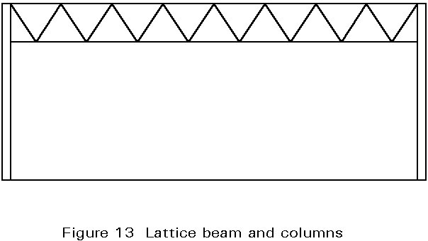
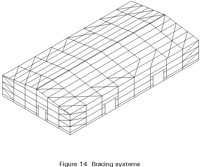
If the building has roof trusses (Figure 7), or if only the top booms of the lattice girders are connected to the column (Figure 13), the frame is effectively pinned at eaves level. To provide in-plane stability, either the column bases should be fixed or longitudinal girders should be provided in the plane of the roof (Figure 14). These girders span between the gable ends, which must be braced appropriately. If the building is long, or is divided by expansion joints, longitudinal bracing may not be practicable and the columns must have fixed bases.
Buildings using lattice girders or truss roofs also need bracing to provide longitudinal stability.
Bracing members for industrial buildings commonly use circular hollow sections, rods or angles.
When cranage is provided the stability requirements need further examination, since longitudinal and transverse surge from the crane increases the forces in the bracing systems.
The structure may be treated either as a 2-D or 3-D system.
Bracing systems are analysed as if pin-jointed. When cross-bracing is used, for example in vertical bracing, only the members in tension are assumed to be effective (compression members are assumed ineffective because of buckling).
The choice of the method of global analysis, either plastic or elastic, of portal frames at the ultimate limit states depends on the class of the cross-section.
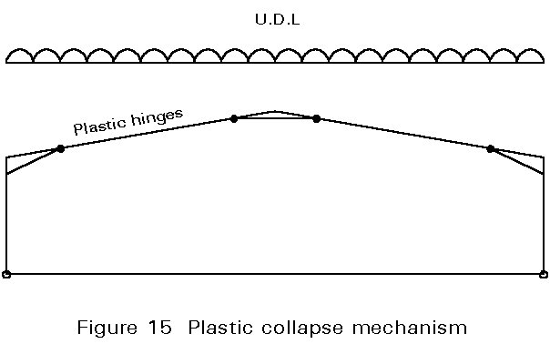
An example of the plastic collapse mechanism of a frame with haunches is given in Figure 15. Buildings with cranes should always be analyzed elastically. Elastic analysis should always be used to determine deflections under service loading.