ESDEP WG 7
ELEMENTS
To introduce two-dimensional trusses: types, uses and principal design considerations.
None.
None.
This lecture presents the types and uses of trusses and lattice girders and indicates the members that are most often used in their construction. A discussion of overall truss design considers primary analysis, secondary stresses, rigorous elastic analysis, cross- braced trusses and truss deflections. The practical design of truss members is discussed.
The truss or lattice girder is a triangulated framework of members where loads in the plane of the truss or girder are resisted by axial forces in the individual members. The terms are generally applied to the planar truss. A 'space frame' is formed when the members lie in three dimensions.
The main uses are:

The principle of a truss is simple. The structure is composed of top and bottom chords triangulated with diagonals in the webs so that each member carries purely axial load. Additional effects do exist but in a well designed truss these will be of a secondary nature.
A global moment on a truss is carried as compression and tension in the chords. A global shear is carried as tension or compression in the diagonal members. In the simplified case, where joints are considered as pinned, and the loads are applied at the panel points, the loading creates no bending moment, shear, or torsion in any single member. Loads applied in such a way as to cause bending, shear, or torsion will usually result in inefficient use of material.
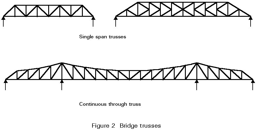
Trusses and lattice girders are classified in accordance with the overall form and internal member arrangement. Pitched trusses are used for roofs. Parallel chord lattice girders are used to support roofs and floors and for bridges, although in continuous bridges, additional depth is often required at the piers. In the past, proper names were given to the various types of trusses such as the Fink truss, Warren girder, etc.. The most commonly used truss is single span, simply supported and statically determinate with joints assumed to act as pins.
The Vierendeel girder should also be mentioned. It consists of rigid jointed rectangular panels as shown in Figure 1d. This truss is statically indeterminate and will not be further considered in this lecture, although it has a pleasing appearance and is often used in foot-bridges.
The saving over a plate girder is clear when the webs are considered. In a truss the webs are mainly fresh air - hence less weight and less wind force.
A truss can be assembled from small easily handled and transported pieces, and the site connections can all be bolted. Trusses can have a particular advantage for bridges in countries where access to the site is difficult or supply of skilled labour is limited.
Truss, lattice girder and bracing members for buildings are selected from:
For bridges, members are selected from:
Typical sections are shown in Figure 4.

The selection of members depends on the location, use, span, type of connection and the appearance required. Hollow sections are more expensive than open sections but are cheaper to maintain and have a better appearance. However, in exposed trusses corrosion can occur at the crevices which are formed at gusset positions. Angles are the sections traditionally used for small span truss construction.
The main types of loads on buildings are shown in Figure 5, namely:

In special cases, trusses resist dynamic, seismic and wave loads. A careful watch should be kept for unusual loads applied during erection. Failures may occur at this stage when the final lateral support system is not fully installed.
For bridges, in addition to the dead loads and the vertical effects of live loads due to highway or railway loading, horizontal effects of live load have to be considered. These include braking and traction effects, centrifugal loads and accidental skidding loads. Temperature effects are significant in some bridges.
Trusses may be single span, statically determinate or indeterminate, or may be continuous over two or more spans, as shown in Figure 6. Only single span, statically determinate, trusses are considered in this section.

A truss is usually statically determinate when:
m = 2j - 3,
where m is the number of members in a truss
j is the number of joints.
However compliance with this formula for the truss as a whole does not preclude the possibility of a local mechanism in part of the truss.
Manual methods of analysis for trusses, where the loads are applied at the nodes, are joint resolution, the method of sections and the force diagram. Joint resolution is the quickest method for analysing parallel chord lattice girders when all the forces are required. The method of sections is useful where the values of the forces in only a few critical members are required. The force diagram is the best general manual method. Computer programs are also available for truss analysis.
In many cases in the design of trusses and lattice girders, it is not necessary to consider secondary stresses. These stresses should, however, be calculated for heavy trusses used in industrial buildings and bridges.
Secondary stresses are caused by:
They are discussed in detail below:
Trusses should be detailed so that either the centroidal axes of the members or the bolt gauge lines meet at a point at the nodes. Otherwise, members and connections should be designed to resist the moments due to eccentricity. These moments should be divided between members meeting at joints in proportion to their rotational stiffnesses. Stresses due to small eccentricities are often neglected.
Moments due to these loads must be calculated and the stresses arising combined with those due to primary axial loads; that is the members concerned must be designed as beam-columns. This situation often occurs in roof trusses where the loads are applied to the top chord through purlins which may not be located at the nodes, as shown in Figure 7. The manual method of calculation is first to analyse the truss for the loads applied at the nodes which gives the axial forces in the members. Then a separate analysis is made for bending in the top chord which is considered as a continuous beam. The ridge joint E is fixed because of symmetry, but the eaves joint A should be taken as pinned; otherwise, moment will be transferred into the bottom chord if the joint between the truss and column is assumed to be pinned. The top chord is designed for axial load and bending. Computer analysis is mentioned below.

Stresses resulting from secondary moments are important in trusses with short thick members. Approximate rules specify when such an analysis should be made. Secondary stresses will be insignificant if the slenderness of the chord members in the plane of the truss is greater than 50 and that of most of the web members is greater than 100. In trusses in buildings, the loads are predominantly static and it is not necessary to calculate these stresses. The maximum stresses from secondary moments occur at the ends of members and are not likely to cause collapse. However, where fatigue effects are significant, these secondary stresses have to be considered. The method of analysis for secondary moments is set out below.
Rigid jointed, redundant or continuous trusses or trusses with loads applied between the nodes can be analysed using a plane frame program based on the matrix stiffness method of frame analysis. The truss can also be modelled taking account of joint eccentricity. Member sizes must be determined in advance using a manual analysis. All information required for design is output including joint deflections.
It is important that a consistent approach is adopted for analysis and design. This means that if secondary moments are to be ignored then the primary axial forces to be used in design must be obtained from the simple analysis of the truss as a pin jointed frame. The axial forces obtained from a rigid frame computer analysis may be modified considerably by the joint moments.
In the bracing provided to stabilise multi-storey buildings, the panels often have cross-diagonals as shown in Figure 8a. It is customary to consider the truss as statically determinate, with only the set of diagonals in tension assumed to be effective. When the wind reverses the other set becomes active.
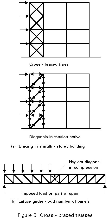
Another common case is the lattice girder with an odd number of panels. The centre panel is cross-braced as shown in Figure 8b. Under symmetrical loading there are no forces in these diagonals. If imposed load is placed over part of the span, only the diagonal in tension is assumed to be effective.
Stringer bracing, braking girders and chord lateral bracing are needed to transmit the longitudinal live loads and the wind and/or earthquake loads to the bearings and also to prevent the compression chords from buckling.
For the top laterals, a diamond system with kickers at the panel points halves the transverse effective length of the compression chord as shown in Figure 9.
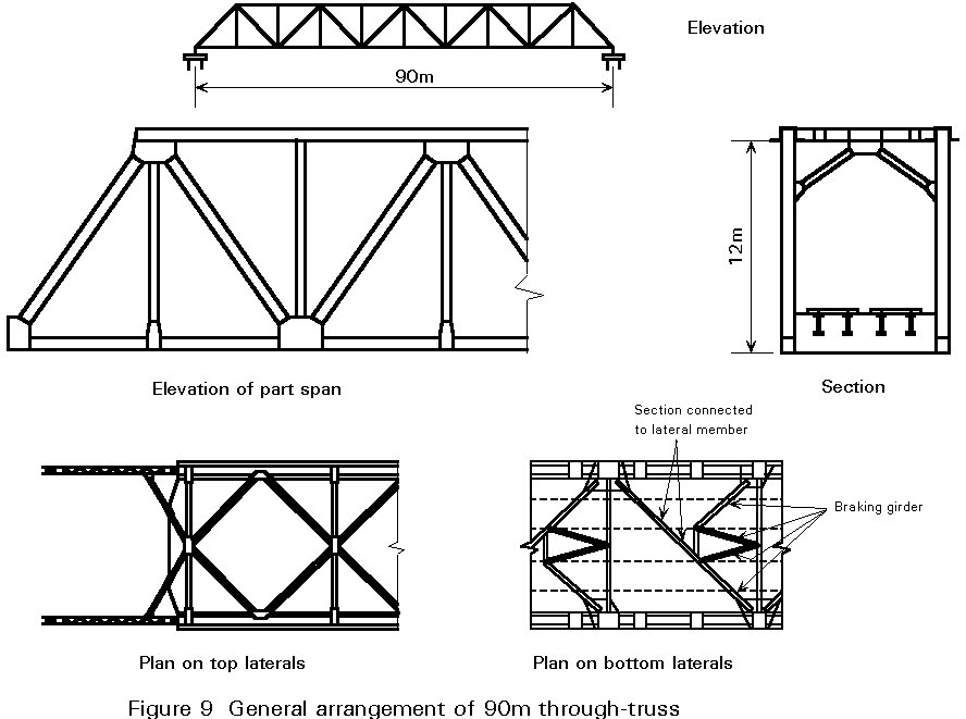
For railway bridges, Figure 9 illustrates an economic lateral system at deck level which consists of a simple single member which doubles up as part of the braking girder. The lateral is supported by the stringers, so the effective length is only about a third of the panel length.
Wind loading on diagonals and verticals can be split equally between top and bottom lateral systems, remembering that the end portals (either diagonals or verticals) have to carry the load applied to the top chord down to the bottom chord.
Obviously where only one lateral system exists (as in semi-through or underslung trusses) then this single system must carry all of the wind load.
In addition to resisting externally applied transverse loads due to wind, etc., lateral bracing stabilizes the compression chord. Its presence is necessary to ensure that reasonably small effective lengths are obtained for the truss members. Lateral bracing is also required at all kinks in the chords where compressive loads are induced into the web members, irrespective of whether the chord is in tension or compression.
The deflection for a pin jointed truss can be calculated using either the strain energy or virtual work method. The deflection using the strain energy method is given by:
d = S FuL/EA
where:
A is the area of a truss member
E is the modulus of elasticity
L is the length of a truss member between nodes
F is the force in a member due to the applied loads
u is the force in a member due to unit load applied at the truss node and in the direction of the required deflection.
The Williot-Mohr graphical method can also be used to determine truss deflections. If a computer analysis is carried out, joint deflections are given as part of the output.
A truss may be cambered during fabrication to offset deflections due to applied loads. The term cambering means that a given upward deflection can be built into, say, a nominally horizontal truss during fabrication by adjusting the member lengths slightly to cause the truss to bow upwards.
The truss should be analysed for the separate load cases. These cases are combined to give the most severe conditions for design of each element. Some important aspects of design are set out below.
Maximum slenderness ratios are normally defined in codes, and these often limit the minimum size of the members that can be used in light trusses.
Acceptable maximum slenderness values are:
Members resisting dead and imposed load - 180
Members resisting wind load - 250
Any member normally acting as a tie but subject to reversal of stress due to wind - 350
These limits ensure that reasonably robust members are selected when only light loads are involved. Wind loads are transient and larger slenderness values are permitted than for dead and imposed loads. These rules also reduce the likelihood of damage occurring during transport and erection. In this regard it has been common practice to specify that the minimum sizes for angles should be as follows:
For the design of members in trusses where secondary bending stresses are insignificant, the following assumptions are made:
For web members the buckling length for in-plane buckling may be taken as 0.9L, where L is the length between truss nodes.
Figure 10 shows roof trusses in place in a building with the purlins providing lateral support to the top chord, and a lower chord bracing system providing lateral support to the bottom chord.

Two common internal truss members are the single angle discontinuous strut connected to a gusset or another member and the double angle discontinuous strut connected to both sides of a gusset or another member. These should be connected by at least two bolts or the equivalent in welding. Eurocode 3: Part 1.1: Clause 5.8.3 states that the end eccentricity may be ignored and the struts designed as axially loaded members in accordance with that clause [1].
Generally the truss members in bridges are much larger than in buildings, and much more attention has to be paid to the detailed design of the member. Eurocode 3: Part 1.1 [2] applies to buildings, and the very conservative buckling length values of L and 0,9L are not very significant for relatively small span trusses [1]. However, for bridges, where absolute economy in steel weight is vital, it is assumed that the matter of effective length will be dealt with fully in Eurocode 3: Part 2 [3].
When making up the section for the compression chord, the ideal disposition of material will be one that produces a section with radii of gyration such that the ratio of effective length to radius of gyration is the same in both planes. In other words, the member is just as likely to buckle horizontally as vertically.
The depth of the member needs to be chosen so that plate dimensions are sensible. If they are too thick, the radius of gyration will be smaller than it would be if the same area of steel was used to form a larger member using thinner plates. The plates should be as thin as possible without losing too much material when the effective section is derived.
Structural hollow sections connected by welding may be fully effective. The 'effective area' is to be used for angles connected through one leg. Theoretically rounds or cables could be used; but these are unsuitable for practical reasons, because they lack stiffness and are easily damaged. The same minimum sections for angle members set out above for compression members should be adopted for tension members.
Tension members should be as compact as possible, but the depths will have to be large enough to provide adequate space for bolts at the gusset positions. The width out-of-plane of the truss should be the same as that of the verticals and diagonals so that simple lapping gussets can be provided without the need for packing.
Allowance has to be made for the nett section when bolt holes are removed. It should be possible to achieve a nett section about 85% of the gross section by careful arrangement of the bolts.
For buildings, Eurocode 3: [2] only requires fatigue assessment for:
a. Members supporting lifting appliances or rolling loads.
b. Members subject to repeated stress cycles from vibrating machinery.
c. Members subject to wind-induced or crowd-induced oscillations.
Even in these cases, assessment is not required if the stress range or number of stress cycles is low.
Otherwise, members subject to reversal of load should be designed for the worst condition.
For bridges fatigue assessment is required for all members subject to reversal of load.
a. Buildings
1. It is not always economic to make every member a different size. The designer should rationalise the sizes and use only two or three different sections in small span trusses.
2. Minimum sizes should be adopted to prevent damage during transport and erection. Recommendations are set out above.
3. Safe load tables are very useful and members subjected to axial load can be selected directly. Members subjected to axial load and moment must be designed by successive trials. Select the initial size by assuming the compression resistance is 60% of full resistance.
4. Large trusses must be sub-divided for transport. Bolted site splices are used to assemble the truss on site.
b. Bridges
1. The optimum value for the span-to-depth ratio depends on the magnitude of the live load that has to be carried. It should be in the region of 10, being greater for road traffic and less for rail traffic. (For twin track rail loading the ratio would drop to about 71/2.) However, one should always make a check on the economic depth for the given bridge.
2. An even number of bays should be chosen to suit the configuration of diagonals. If an odd number is chosen there will be a central bay with crossed diagonals. This is not usually desirable except perhaps at the centre of a swing bridge. The diagonals should be at an angle between 50° and 60° to the horizontal.
3. Grade 50 steel should be used for the main members with Grade 43 used only for members carrying nominal load, unless the truss has to be fabricated in a country where the supply of higher grade steel is a problem. For a truss designed using Grade 50 steel, the amount of Grade 43 steel used would normally be about 7%.
4. The problems that may confront the bridge maintenance team should be fully appreciated. Details which could trap rainwater, dirt and debris should be avoided. All exposed areas should be fully accessible for painting. Box sections make painting easier, but rolled hollow sections leave nasty crevices at gusset positions unless the joints are welded.
[1] Eurocode 1: "Basis of Design and Actions on Structures": CEN (in preparation).
[2] Eurocode 3: "Design of Steel Structures": ENV 1993-1-1: Part 1.1: General rules and rules for buildings, CEN, 1992.
[3] Eurocode 3: "Design of Steel Structures", Part 2: Bridges, CEN (in preparation).