ESDEP WG 11
CONNECTION DESIGN: STATIC LOADING
To identify the ways in which structural connections are made in steel buildings, to discuss the importance of a proper choice of connection type on both overall structural behaviour and economics and to present the basic principles of connection design.
Lecture 1B.5.1: Introduction to Design of Simple Industrial Buildings
Lecture 1B.7.1: Introduction to Design of Multi-Storey Buildings
Lecture 3.1.1: General Fabrication of Steel Structures I
Lecture 3.5: Fabrication/Erection of Buildings
Lecture 11.1.2: Introduction to Connection Design
Lectures 11.2: Welded Connections
Lectures 11.3: Bolted Connections
Lecture 11.4: Analysis of Connections
Lecture 11.5: Simple Connections for Buildings
Lecture 11.6: Moment Connections for Continuous Framing
Lecture 11.7: Partial Strength Connections for Semi-Continuous Framing
Lecture 11.8: Splices
Lectures 13: Tubular Structures
The need for various forms of structural connections in steel buildings is established and their basic forms are identified. Methods of making connections are discussed within the context of transferring local forces between components, ensuring consistency of overall structural behaviour and the practical aspects of fabrication and erection. The basic principles of connection design are thus established.
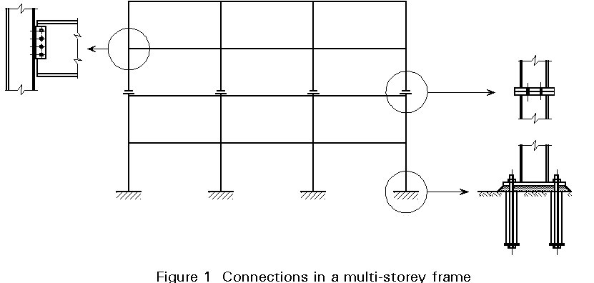
Steel frame buildings consist of a number of different types of structural elements, each of which has to be properly attached to the neighbouring parts of the structure. This will involve the use of several forms of connection. The main classes of connection are:
i) Where a change of direction occurs, e.g. beam-to-column connections, beam-to-beam connections and connections between different members in trusses.
ii) To ensure manageable sizes of steelwork for transportation and erection e.g. columns are normally spliced every two or three storeys.
iii) Where a change of component occurs, including connection of the steelwork to other parts of the building, e.g. column bases, connections to concrete cores and connections with walls, floors and roofs.
Figure 1 gives examples of connections within the context of a multi-storey frame.
Connections are important parts of every steel structure. The mechanical properties of the connections are of great influence on the strength, stiffness and stability of the whole structure.
The number and the complexity of the connections have a decisive influence on the time that is necessary for the statical analysis and the production of drawings.
Production of connections, i.e. cutting, drilling and welding of main members, plates, cleats and stiffeners, consumes much of the work content in the fabrication shop. The ease with which the site connections can actually be made is a key factor in erection.
Thus the selection, design and detailing of the connections in a building frame has a very significant influence on costs.
Connections in steel structures are normally made using welds and/or bolts.
Welds
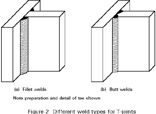
Although various forms of structural welds are possible, fillet welding of the type illustrated in Figure 2a is normally to be preferred to butt welding as shown in Figure 2b, since it requires only simple preparation of the parts to be joined, can usually be accomplished with relatively simple equipment and does not require special skills of the welder.
Although welding may be conducted on site, it tends to be expensive for the following reasons:
Site joints are, therefore, normally made using bolts.
Bolts
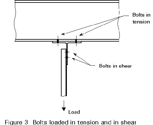
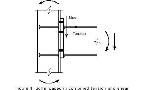
Depending on the shape of the connection and the location of the bolts, they are loaded in tension, in shear or in combined tension and shear, see Figures 3 and 4.
To accommodate some mismatch in hole distances and bolt diameters, holes are normally drilled 2mm in diameter greater than the bolt diameter (clearance holes). Where displacements due to these clearances are not acceptable, the bolts may be preloaded to prevent slip. For statically loaded structures, such as buildings, preloaded bolts should normally be avoided. The special treatment of the contact surfaces to obtain a high and reliable value for the slip factor and the procedures to achieve the design preload are expensive.
Other Parts
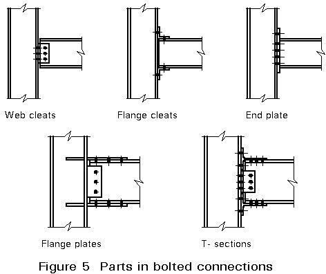
In addition to bolts and welds, other parts are often also necessary to transfer forces, e.g. plates and angle cleats. Figure 5 shows some examples in beam-to-column connections.
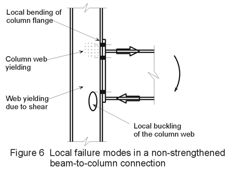
Potentially weak areas may occur in connections. In the beam-to-column connection in Figure 6 such areas may be the column flange and the column web. The transmission of high localised forces in the column may cause local yielding and local buckling. These failure modes may be decisive for the moment resistance of a connection. For example, the moment resistance of the connection shown in Figure 6 is lower than the full plastic moment of the beam.
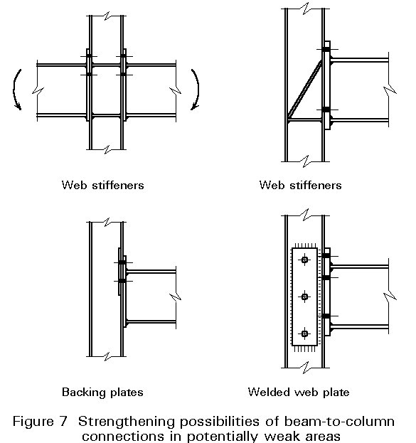
If necessary, the moment resistance can be increased by strengthening the relevant weak areas of the connections, see Figure 7.
For buildings designed to resist essentially static loading, including wind loads, it will normally be sufficient to design connections to resist forces that primarily act in one direction only. However, in seismic zones large load reversals may occur. This load reversal will normally require a different approach to the design of the load-resisting structure, leading to different forms of connection.
For multi-storey buildings the connections between the main structural elements may conveniently be classified as:
This list does not, of course, include connections between the main framework and other parts of the structure, e.g. beams to floors, attachment of the cladding, etc. Despite the different geometrical configurations and detailed structural requirements of the five different types, certain general functional requirements must always be addressed:
Thus the design of any steelwork connection must simultaneously satisfy the needs of structural adequacy, an appropriate type of behaviour and practical engineering. Clearly it will often be possible that different arrangements satisfy each of these needs to differing degrees. A certain amount of judgement and experience in deciding the relative importance of the different design criteria is required to decide which requirement should be given the greatest emphasis in a given situation. Of course, the designer does not have a completely free choice as he must always ensure that the connection is able to transmit the required level of loads. His choice in this respect relates to the exact arrangement selected and, perhaps, to the extent to which a more easily fabricated connection might provide more strength than is actually required.
In this respect also the workshop should have an influence on the design. Its capabilities and equipment should be taken into consideration when detailing connections. Therefore, the detailing work should be undertaken in consultation with the workshop.
Connections involving tubular members require special care as the arrangements used for open sections may not simply be adapted. The main factor is, of course, the limited access that prevents the use of bolts with nuts inside the tube. In cases where the connections may be made wholly by welding, e.g. shop fabrication of trusses, the solution is clear. However, site joints need particular attention, especially if the clean lines which are often a factor in selecting a tubular configuration are to be preserved. More information is provided in the Lectures in group 13.
In order to give an impression of the wide variety of possible designs, the following descriptions include figures to provide examples of the connection types mentioned above.
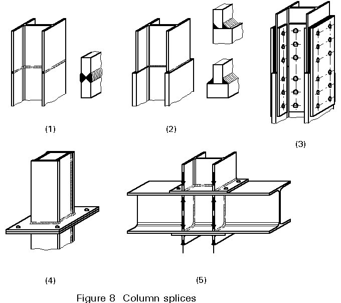
8.1 and 8.2: These are welded splices. Where there are different thicknesses of the plates, cheaper fillet welds can be used. It should be recalled that welding may not be the most appropriate connection means for site connections.
8.3: Bolted splice. The vertical forces may be assumed to be transmitted by bearing and/or through the plates. The plates also serve to transmit bending moments and shear forces. Where there is unequal thickness of the flanges/webs, intermediate plates are necessary.
8.4: A frequently used splice connection. Due to the welding in the workshop, the plates may not be perfectly flat. Normally no subsequent machining is necessary to flatten these plates.
8.5: Sometimes it is easier to make the beam continuous. To transmit the forces and for stability reasons, it is necessary to stiffen the beam between the column flanges.
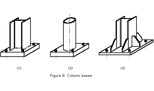
9.1 and 9.2: Thick base plates need no stiffening. Normally this is the cheapest solution.
9.3: Thinner base plate with stiffeners as used in old designs.
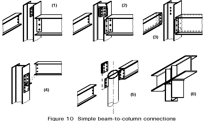
10.1: Connection with fin plates welded to the column. The beam is connected single sided.
10.2: Bolted connection with angle cleats. Cleats may be welded to either member as an alternative.
10.3: Connection with thin flexible endplates welded to the beam.
10.4: Bolted connection with angle cleats. The horizontal angle cleat provides extra bearing resistance.
10.5: For a thick wall of a tube, the plates can be welded directly to the wall without making a sleeve in the tube to have a continuous plate. For more details involving tubes, see Lectures 13.
10.6: The stiffness depends largely on the thickness of the end plate on the column and the thickness of the flange of the beam. The stiffening plates may be omitted in many cases.
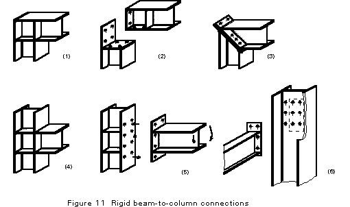
11.1: Fully welded connection.
11.2: Bolted knee - connection.
11.3: Knee-connection with welded end plates.
11.4: Welded T-connection.
11.5: Bolted T-connection.
11.6: Bolted end plate connection. It is assumed that another beam is connected on the other side of the web.
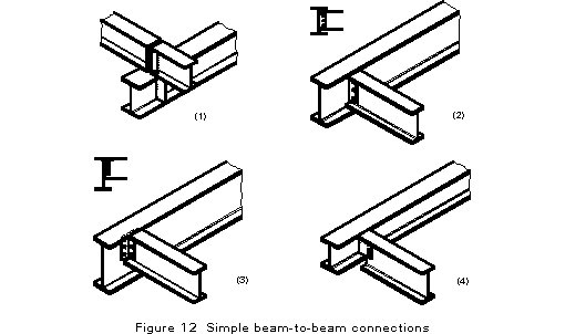
12.1: Depending on the geometry and the applied forces, stiffeners may or may not be necessary. This connection has the advantage of cheap fabrication but the disadvantage that its total construction height is higher than that of the other designs in Figure 12.
12.2: In this connection there is no need to make a cope as in the connection 12.3. Therefore it is also a cheap design to fabricate.
12.3: The top flanges are at the same height. The cope makes this design more costly than the design of 12.2.
12.4: The beam to be connected is higher than the main beam. This design is rather cheap to fabricate. The hinge will be located where the plate is welded to the web.
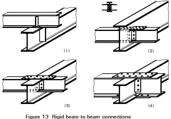
13.1: This design is comparable to the design of 12.1. Of course stiffeners should be omitted where possible.
13.2: The tensile force in the top flange is transmitted via the flange plate that crosses the web of the main beam through a sleeve. On the compression side, small compression parts may be necessary to introduce the compression force.
13.3: In this design also a cope of the beam is necessary, as in 12.3.
13.4: Both beams have the same height.
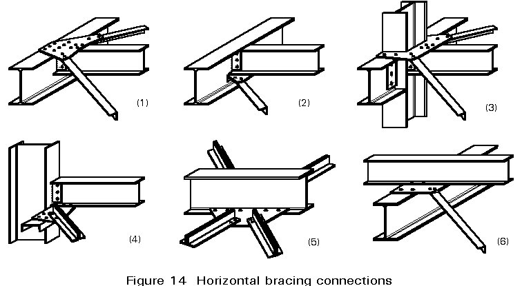
14.1, 14.2, 14.3: The gusset plates on the top flanges may be a problem when metal roof or floor decking is used.
14.4, 14.5, 14.6: The channel section in Figure 14.4 is needed as a chord for the horizontal truss.

15.1, 15.2, 15.3, 15.4: Various possibilities for the connections of bracings.
As already indicated, there are a great number of requirements to be met when designing connections. The requirements relating to structural behaviour are examined further in other Lectures 11. The basic requirements for economy are discussed further below.
The costs for a steel structure can be divided into costs for material and costs for labour as follows:
| Material | 20 - 40% | |
| Calculation | } | |
| Drawings | } | |
| Fabrication | } | 60 - 80% |
| Protection | } | |
| Erection. | } |
From this division of costs it can be concluded that a saving of labour costs has potentially more influence on the overall costs of steel structures than saving on material.
An influencing factor is the relation between cost per kg steel and cost per man hour.
In the past decades the price of steel has increased considerably less than the price of labour. This trend, together with developments in fabrication technology, means that structural designs that were optimal 10 years ago may not be competitive now.
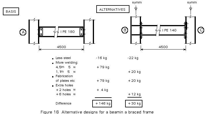
A major part of labour costs has a direct relation to the design and fabrication of connections. It is often better in design to save labour at the expense of material. This fact can be illustrated with some simple examples. To estimate the costs, the following assumptions are made:
In Figure 16 a beam in a braced frame is given. The basis is a design with simple connections to transmit shear force only. When the "hinges" are replaced by moment connection as in [B] and [C], then for the beam an IPE 140 can be selected instead of an IPE 180. However, due to the extra costs for the connections, the alternatives [B] and [C] are more expensive, especially [B]. The difference with [C] which uses backing plates to strengthen the column flanges is less. When the same exercise is carried out for a beam with greater span, e.g. 10m, it is found that alternative C is the cheapest.
The balance between moment resistance in the connection and in the beam is discussed further in Lecture 11.7 on semi-continuous design.
Another example is the base plates illustrated in Figure 9. It can easily be shown that the thick base plate without stiffeners is the cheapest in nearly all cases.
For the example with the beam-column connections, it should be mentioned that the alternative A has no welds. This may mean that the flow of material in the fabricator's shop is simpler as no stop is needed at the welding station.
Some other aspects which facilitiate economy in design are:
For more information on these aspects, reference is made to the Lectures in group 3, on fabrication and Lectures in group 4A on corrosion.
Drawings of bolts of all kinds and photographs of fixings procedures, plus examples of connection design.
Presents design models and resistance tables for the main connection types.
Informative and well illustrated reference manual covering all aspects of welded design and construction.
Comprehensive text on theory and design of steel structures. Deals extensively with connections. A detailed treatment of combined loads on fillet welds is of particular interest.
Chapter 6 presents rules covering the design of individual items of connections, e.g. bolts, welds, hole edge distances, etc. Annex J deals in more detail with the design of bolted and welded beam-to-column connections.
Explains how flexibility arises in beam-to-column connections and presents methods for assessing stiffness and strength properties.
SCI/BCSA Publication 205, 2nd Ed, 1993.
Provides design models and some background for the most popular types of: beams to columns, beam to beam, column splice and column base.
Expands on the more practical aspects of connection design; provides tables to facilitate connection design in a "look-up" basis.
Comprehensive coverage of many aspects of connection behaviour and design.