ESDEP WG 11:
CONNECTION DESIGN: STATIC LOADING
To present the basic guidelines and concepts for the design of splices in buildings as well as basic arrangements for splices in tension and compression members and in members subject to bending. The main aspects of fabrication and erection are briefly reviewed.
Lecture 11.1.1: Connections in buildings
Lecture 11.1.2: Introduction to connection design
Lectures 11.2: Welded connections
Lectures 11.3: Bolted connections
Lectures 11.4: Analysis of connections
Lecture 15B.11: Splices and other Connections in Bridges
Splices are designed to transfer axial force, shear force and bending including parasitic moment and second-order effects. Initially load paths must be determined; the resistance of all components on these load paths must be checked.
A spliced connection is a joint made within the length of a stanchion, a beam or any other structural member. It is aimed at transferring the internal forces from one structural part to the adjacent one without being a weak point of the structure in relation to strength, stiffness and, ductility. This transfer is normally made through different kinds of transitional plate elements which are appropriately fastened onto the member parts.
The reasons why splices are required as well as the advantages and disadvantages of the respective types of fasteners have been discussed elsewhere; see Lectures 11.1. As with any other kind of connection, splices should be designed to the general principles, and design concepts presented earlier, see Lectures 11.1.
There are many ways of making splices. For example, traditional cover plates may used for full load transfer or just for continuity; welds or bolts may be chosen as fasteners.
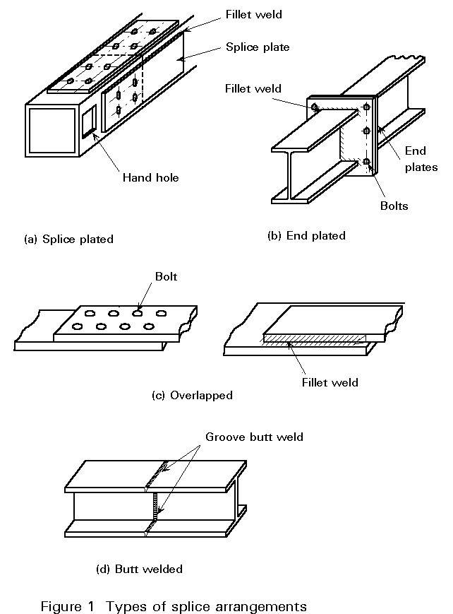
Most splices transfer loads from one structural member to the adjacent part of a similar structural member through either cover plates or end plates. Cover plates may be single, with bolts in single shear, or double with bolts in double shear (Figure 1a).
Where end plates are used in a splice they are usually positioned perpendicular to the member axes and fixed by fillet welds (Figure 1b).
In overlapped splices there is no need for cover plates. Such connections are used especially when splicing single plates or sheeting components. The plate parts are simply overlapped and connected to each other by bolts or fillet welds (Figure 1c), or even by screws for very thin plates or sheeting. Such elementary splice arrangements are not considered further in this lecture.
In a butt welded splice, full continuity of the section is maintained across the joint cross-section. Such splices are used when assembling members of the same or nearly the same serial size (Figure 1d).
Many factors influence the choice of type of splice, e.g. type of loads to be transferred, the types of structural sections - open or closed sections, ease of access, nature of the loading - static or dynamic, with or without load reversal - and stiffness.
The splices shown in Figure 1 illustrate most of the possible arrangements.
The internal forces to be transmitted by a specified splice are firstly, the axial force, bending moment and/or shear force which occur in the joint based on elastic or plastic structural analysis of the structure, assuming continuity through the joint. Secondly, consideration should be given to any second-order effects due to geometric non-linearities and imperfections.
Good practice should require that spliced parts be arranged so that any eccentricity between their respective centroidal axes is avoided. Where eccentricities cannot be prevented, then relevant additional forces and moments should also be taken into account.
In addition, when considering the load paths of the internal forces through the components of the splice, due attention should be paid to possible changes in the magnitudes of the lever arm when the load transfers from the structural part into the splice components, i.e. the internal forces should be carefully identified and the magnitudes of load components determined so that equilibrium is satisfied.
Where the loading is predominantly static, implicit allowance is normally made for plastic redistribution. The stress resultants may thus be transferred according to a statically admissible scheme. This approach is normally acceptable for most building structures.
In contrast bridges are subject to repeated loads. Since this raises the possibility of fatigue, the above simplification with its implied stress redistribution is not applicable to bridge construction to the same extent.
This lecture relates to splices in building structures. The splice arrangements, guidelines and design concepts developed here are also applicable to bridge structures but subject, in addition, to the reservations described above.
Any splice in a building structure, which may be exposed to fatigue loading should, of course, be subject to the same consideration.
Splices in structural members of building structures can be subject to axial forces, to bending and shear or to combined axial force and bending. Only the basic cases are examined below, i.e. respectively tensile or compressive axial force, on the one hand, and uniaxial bending with shear, on the other hand. If a splice is subject to a combination of two or more of these basic action effects, then the combination should be considered appropriately, see Lecture 12.8.
Compared with compression members, which are usually designed for buckling resistance, tension members are generally much more slender and have a smaller cross-sectional area.
Tension members which are likely to be spliced include:
a. tension chords and web members in trusses and lattice girders
b. tension braces and bracing members
c. hangers
d. ropes
Any type of structural shape - open or hollow, single or compound - is appropriate for tension members. The most common sections used in this respect are: rods, flats, channels and angles. For large tensile forces, H and I sections and circular or rectangular hollow sections can be used.
Tensile force is transmitted by the plate elements of the structural tension member in proportion to their cross-section areas. The splice plate(s) associated with each plate element should be designed to resist the relevant tensile force component.
Most splices in tension members use splice plates and overlapped connections. Butt-welded splices are executed in special circumstances; end-plated splices are not frequently used except for hollow sections.
There are two types of bolted splices for tension members, they make use of:
a. bearing bolts, when no special consideration is given to slip in the splices,
b. slip-resistant bolts, which prevent any slip in the splice under service conditions and possibly at the ultimate limit state of the connection. Consequently they provide the joint and the tension member with a larger extensional rigidity.
In bolted connections, the ultimate member strength is reduced by the bolt holes; it may also be reduced by the partial effectiveness and secondary bending due to eccentricity in the connection. In design the influence of the bolt holes is acknowledged by checking the net section. Some account is taken of strain hardening so the design strength may still match that of the gross section. Partial strength and eccentricity effects are covered by empirical rules. Both topics are addressed in Lecture 11.4.2.
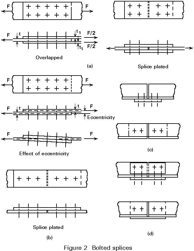
Basically such connections are checked with reference to the design rules developed in Lecture 11.3.1, which are relevant for all the potential failure modes. Though it is desirable that the splice avoids load eccentricity (Figure 2a), there are cases where the tensile force is transmitted eccentrically (Figure 2b). Provided the load eccentricity is kept small, the effects of secondary bending on the ultimate strength of both member and splice may be disregarded, as a result of plastic redistribution. Thus most of the splices in tension members are designed to resist tension only. When the eccentricity of the force is not negligible, then either a safe approximate allowance should be made for bending effects or explicit account should be taken of the latter when designing the splice. For instance, when angles are spliced through one leg only, the outstanding leg is not fully effective and there is a moment due to eccentricity in the connection (Figure 2c); of course the splice illustrated in Figure 2d is far more advisable in this respect.
In bearing-type connections, bolts are designed to resist shear. The basic problem lies in the force distribution amongst the successive rows of bolts over the joint length. Except for long joints (see Lecture 11.4.2) full plastic redistribution is assumed to take place, which allows a uniform load distribution between all the bolts of the splice.
Four failure modes may be considered (Figure 3):
a. Tearing at the net cross-section of the parent plate and/or the splice plate
b. Shearing of the bolt shank or threaded region
c. Bearing between the plate and the bolts
d. Shearing of the plate beyond the end fastener.
The last failure mode (d) should not occur provided that the end distance from the centre of a fastener hole to the adjacent end of any structural part measured in the direction of load transfer is not less than 1,2 do, where do is the hole diameter. Assessment of the resistance of the splice components with regard to other failure modes is explained in Lecture 11.3.1. Attention must be paid to the net cross-section. Where holes are arranged in parallel rows located perpendicular to the tensile force, the net section is obtained by deducting from the gross area the largest total hole area in any cross-section. Should the bolts be staggered then the cross-section to be considered can be any diagonal or zig-zag line extending progressively across the plate with an appropriate correction to take into account the holes not being perpendicular to the direction of load transfer, see Lectures 11.4.4.
Either ordinary bolts or high strength bolts (up to grade 10.9) may be used. Ordinary (4.6) bolts are now only used for minor connections.
Splice connections using preloaded high strength bolts with controlled tightening are usually designed to be slip-resistant at the serviceability limit state. In such connections bolts may come into bearing at a load larger than the service load but lower than the ultimate load. Therefore, there is a need to check slip resistance against the design serviceability shear load and shear resistance of bolts and bearing resistance at the ultimate shear load. The net section of cover plates is not necessarily the weakest component because load is transferred by friction.
Tension splices are rarely designed using tension bolted connections apart from hollow section splices. Where such connections are adopted, high strength bolts (up to grade 10.9) are usually used. Bolt preloading is advisable when the splice is frequently subject to changes in magnitude of tensile load. Preloading is required when fatigue resistance governs the design.
Appropriate arrangements should be made to limit the magnitude of possible prying forces.
Preloaded tension bolted connections are likely to provide the splice with a higher rigidity.
The end plate material should be carefully selected in order to avoid lamellar tearing.
Tensile forces can be transferred either by butt welds which restore the continuity of the material or by fillet welds used in conjunction with overlap(s) or cover plate(s).
For the design of welds, see Lectures 11.2.
Welded connections allow member parts to be fully tensioned, thereby producing full-strength joints. For practical and economic reasons, welding is not generally used for site splices.
When rods and bars are used as tension members they may be threaded at the ends and spliced by connecting them directly through a coupler. The strength is determined by the tensile stress area at the thread. Ropes are connected through end-sockets or terminals which develop the full static strength.
Columns, struts, some web members in trusses and lattice girders, and bracings are amongst the most common compression members.
Since they have a tendency to buckle, compression members are normally more stocky than tension members. Rolled or fabricated sections are most appropriate.
Splices in compression members may use arrangements quite similar to those for tension members. Cover plates and fasteners should be designed based on similar guidelines and design rules. Since they are subject to compression forces, the plate components of the splice should be carefully examined with regard to plate buckling.
In contrast to tension members - where load paths necessarily involve fasteners - compressive loads can be transferred by direct bearing of the adjacent ends of the compression members to be spliced. The faces do not need to be machined providing they are flat within appropriate tolerances. Such tolerances can usually be satisfied by cutting with a milling saw.
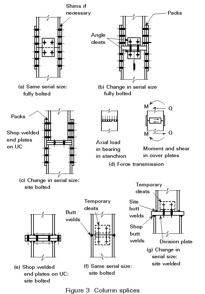
When the members are designed as end bearing, the compressive force is fully transmitted in that way. Such a splice can of course be used when the connected members are of the same serial sizes (Figure 3a). Alternatively a similar arrangement can be designed with a gap between the column ends, in which case all load must be transmitted by the cover plates. Longer plates and more bolts will therefore be required.
When necessary, shims or packing plates should be introduced between the member flanges and cover plates to compensate for fabrication tolerances or differences in rolling weight size.
Though satisfactory for strength, bearing does not provide continuity of bending stiffness. Therefore the splice should include cover plates which restore continuity in flexure about both principal axes and resist any tensile force that would possibly result from secondary moments.
Splice material and fasteners should be proportioned to resist a notional force acting at the abutting ends, in any direction perpendicular to the axis of the member, and whose magnitude should not be less than 2,5% of the compressive force in the member, see Figure 3d.
Bolted splice plated connections may also be used when the member ends are not prepared for bearing. Then the full compressive force must be transferred through the cover plates and fasteners, similarly to tension members. Packings should be used to compensate for significant change in size of the members. Bear in mind that above a certain thickness packing reduces the shear value of the bolts.
Changes in serial size can result from considerations of economy. Major changes occur where columns have to support heavy additional loads over a portion only of their height.
In such situations, to obtain sound load transfer a division plate is required which is fixed onto the deeper member using site bolted cleats or shop welding. The splice is completed by additional cover plates and bolts and possibly packs (Figures 3b and 3c).
Alternatively the arrangement of Figure 3e can be used; two end plates welded onto the adjacent members are assembled by bolting.
Transmission of axial load in bearing requires the faces to be flat within certain defined tolerances.
Division plates are aimed at transferring the compressive force from the smaller member into the deeper one. A dispersion angle not less than 45° should be assumed when determining load paths and bearing stresses. It is usual practice for division plates or end plates to have a thickness not less than 20mm.
In addition to compressive load, the splice components should comply with the requirements for stiffness and notional strength discussed in Section 3.1.
Fully welded splice connections can be made by butt welds of all the member plate components, when the member parts are of the same or very similar size (Figure 3f). When splices must allow for a change in serial size, both member parts are preferably welded onto a division plate of appropriate thickness (Figure 3g).
Butt welds should be proportioned to restore the continuity of the material.
Fully site welded splices (Figures 3f and 3g) require special consideration during erection; the adjacent structural parts must be temporarily guyed or propped until site-welding is completed. Temporary cleats are helpful in this respect.
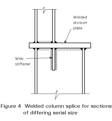
Where there is an appreciable change in serial size and heavy compressive loads, an abnormally thick division plate can be required. As an alternative, a thinner, division plate may be used with additional stiffeners to assist in diffusing the load through the splice as shown in Figure 4.
Because division plates are subject to transverse forces, their thickness is mainly governed by bending strength. Their material should be chosen lamination free, otherwise the bending resistance could be compromised.
Compression members are seldom subject to pure axial force only. Most frequently they have also to resist some additional bending and shear. Supplementary effects should be taken into account by the use of the guidelines in Section 4 and appropriate design rules have been provided Lectures 11.4.
Splices in columns are most often located at their foot close to the floor level. Where necessary they can be masked within the floor depth.
In members which are predominantly subject to bending, splices are normally placed close to points of contraflexure, i.e. at sections where bending is the least.
In addition to the reasons for using splices already mentioned, the designer may wish to use splices as an aid to precambering or to change sections to achieve economy by reducing member sizes in regions of low moment.
Beam splices are aimed at transferring bending and associated shear. Either welded or bolted splice connections are possible and, for these latter, either shear connections or tensile connections can be used. The most common types of splices when beam parts have the same serial size are shown in Figure 5.
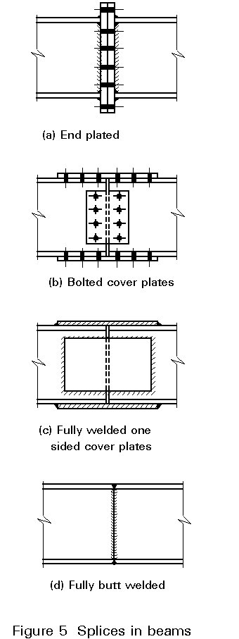
Fully welded splices using full-penetration groove welds (Figure 5d) are common in built-up members and plate girders and possibly in rolled beams. They are executed in the workshop. Alternatively fillet welded connections with one sided or double sided welded cover plates may be used (Figure 5c). This type of connection may be preferred to butt welds when executed on the site, especially when dimensional control is a critical factor.
Full-penetration butt welds are at least as strong as the base material. Therefore no strength check is necessary provided the welds restore at least the relevant plate thickness.
When splices use bolted connections, high strength bolts are commonly used in order to reduce the splice length. Preloaded bolts will provide a better stiffness and reduce deflections because they prevent slip. Such a consideration can be of major importance where service conditions determine the beam design.
Each plate component of the splice shear connection should be designed to transfer the forces in the elements it connects. Cover plates are normally placed both sides of webs and on one or both sides of flanges. For the sake of simplicity and based on the static theorem of plastic design, reference is commonly made to a statically admissible force distribution, where the bending moment is resolved into a pair of equal but opposite flange forces while the web provides resistance to shear only.
Where the beam splice is at a change in serial size then the above arrangements may be used provided due allowance is made for appropriate packs and possibly web stiffeners to diffuse flange forces. Such situations sometimes arise from architectural considerations or tight local headroom requirements.
Where, rarely, the beam splice is located at a point of maximum moment it is important to ensure that the splice has a rotation capacity that is consistent with the global analysis of the overall structure. Where, as is usually the case the splice is located at a region of low moment no special consideration of rotation capacity is required.
End plates shall be lamination free.
Splices in members subject to combined axial force and bending should be proportioned by taking appropriate account of the guidelines listed in the above sections for the respective components of loading.
Special care should be taken when identifying the load paths as well as the forces to be transmitted by each splice component.