ESDEP WG 3
FABRICATION AND ERECTION
To describe the general nature and sequence of steelwork fabrication and the erection of light/medium single and multi-storey buildings with emphasis upon the overall cost economies of the complete structure.
None are essential.
The following lectures might be helpful:
Lecture 2.1: Characteristics of Iron-Carbon Alloys
Lecture 2.2: Manufacturing and Forming Processes
Lectures 2.3: Engineering Properties of Metals
Lecture 2.4: Steel Grades and Qualities
Lecture 2.5: Selection of Steel Quality
Lectures 3.1: General Fabrication of Steel Structures
Lecture 3.3: Principles of Welding
Lecture 3.4: Welding Processes
Lecture 15A.8: Offshore: Fabrication
Lecture 15B.10: Introduction to Bridge Construction
A typical production network and workshop layout is described, assuming an ideal layout for maximum efficiency. This is followed by examples illustrating alternative solutions for greater economy. Site planning and organisation and erection methods, including stability and safety aspects, are also outlined.
The fabricator's role is to convert rolled steel into finished goods with added value. This is achieved by selling workmanship and machine utilisation on a competitive basis where costs are directly related to time.
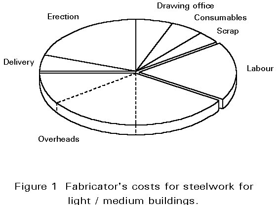
Fabricators rely increasingly upon production engineering techniques. Their continued success in this direction depends upon better standardisation. Time and therefore labour costs can be cut significantly by the repetition of dimensions and geometry, member sizes and shapes, centres and diameters of bolts, etc. All of these are amenable to rationalisation. Further economy is derived by reducing the number of detailed components, which tend to be labour intensive to produce, even when this results in heavier parent members. The cardinal rule is that, relatively, labour is expensive but material is cheap (Figure 1).
Fabrication costs are estimated by separating the various activities into categories such as cutting, drilling and welding which enables man hours to be allocated and valued to arrive at a total price.
Relying upon a combination of historical data and practical experience, the cost build-up bears little relationship to the weight of steel involved, although cost references in ECU/tonne can be a useful index for rapid comparison of different classes of work.
A typical breakdown in costs, in the light to medium category, shows that over 50% of the fabricator's cost is absorbed by labour charges and overhead expenses (Figure 1).
It is customary to recover such expenses as a contributory factor to labour. If the ratio between labour and overheads is 1: 2½, it is significant that for every 100 ECU of labour cost incurred, the amount chargeable would be 100+250=350ECU.
Fabricating companies differ widely in layout, capacity and scope. Whilst the extent and nature of the services available is influenced by policy and resources, the basic flow of activities tends to follow a similar pattern. This can be visualised as a tunnel for the main flow or Primary Operations, supported by branches or Secondary Operations (Figure 2).
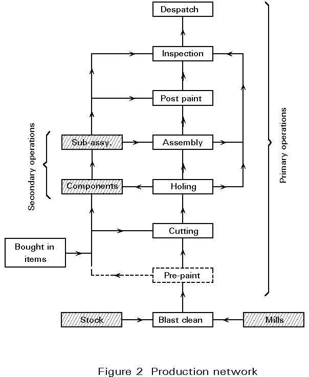
This network forms the basis for production control, which is time related to cost standards. Output must be geared to the sequence of the construction programme. This rarely coincides with the most effective use of all resources. The system has to be extremely flexible to respond to changes in demand whilst minimising disruption or costly delays.
The planning objective is to schedule production so that raw material is transformed into a finished state within an allocated time.
Since most of the important machine tools, such as saws, are sited at the start of the primary production line, the flow of material has to be sustained by an independent supply of essential components such as brackets, cleats and plates in the correct quantities and in the correct order.
This is the task of secondary production together with sub-assembly of detailed fabrications in suitable cases. Bought-in (BI) items or services of a specialised nature such as forgings, pressings or even non-destructive testing have to be available at the correct time.
Steel framed buildings are mainly constructed as a series of linear elements using standard sections. The preparation area for these is typified by a group of fixed work sections consisting of (Figure 3):
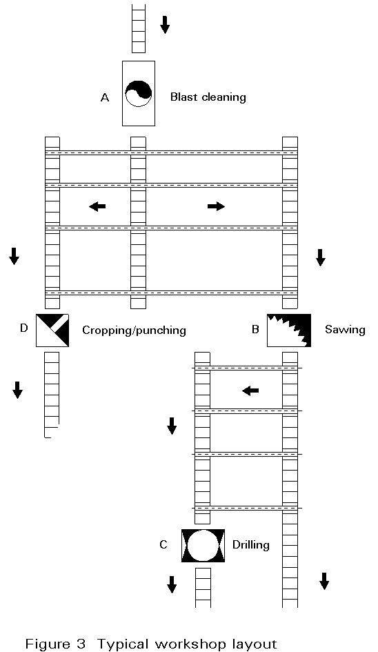
A. Blast cleaning
B. Sawing
C. Drilling
D. Cropping/Punching
The initial step is to pass the steel through a blast cleaning cabinet at "A" to remove any surface rust and mill scale. Various levels of surface treatment are available, but for most buildings, a standard of SA 2½ to the Swedish specification SIS 055900 is adequate. This requires at least 95% of the surface to be clean.
The next stage is to transfer the material to the sawing station at "B" for cutting to length followed by drilling of holes at "C". In a number of workshops, sawing and simultaneous 3 axis drilling may be combined as one activity. Alternatively, angle sections and flats of suitable thickness for cropping and punching would be routed directly to "D".
For speed and ease of handling, sections are transported increasingly by a system of powered conveyors fed by cross transfers. The latest automation now allows all operations and material flow to be conducted from a central numerically controlled console.
Because plates are less stiff, these tend to be more awkward to handle. Lifting and handling is usually carried out by an overhead magnetic crane for subsequent cutting by flame or guillotine in a separate plate working area.
At this stage the main elements on the primary flow are joined by secondary components, end plates, stiffeners, etc. for fitting and assembly, mostly by welding. Depending upon the nature and purpose of the structure, some bolting may be used, if only for trial alignment. However, as a general rule, shop connections are welded and site connections bolted.
Due to variations in the size and nature of the work carried out in any period, the assembly area has to be extremely flexible and well serviced by cranes. Output must be geared to the sequence of the construction programme. As a result designated areas may have to be switched rapidly from beams and columns to bulky lattice girders.
Further planning complications arise because the most cost effective use of workshop labour and equipment rarely coincides with site requirements. It is for this reason that seemingly simple modifications are costly to execute once production has commenced.
Where priming paint is required, elaborate specifications, which are not necessary for steelwork contained within a normal building environment, can easily add 20% to fabrication costs. The function and future maintenance requirements should be considered in each case, rather than adopting a blanket philosophy.
Paint coatings for structural steelwork should "flash off" fairly rapidly to allow further handling and to minimise congestion. Whilst brushing is suitable for touching up minor damage, large surfaces can only be covered economically by spraying. Spraying can be carried out manually or automatically where the work is conveyed through an enclosed cabinet containing the spray nozzles. The process may also be supplemented by a drying kiln.
After assembly, inspection concentrates mainly upon overall dimensions, position of cleats, holes and so on, to ensure proper alignment during site erection. Framed elements, such as latticed girders, are self checking to a certain extent by virtue of the fit of members during assembly. This principle is often used to prove complex structures by trial erection prior to despatch.
Where in-depth weld examination is required, it should be conducted at the appropriate stage determined by the nature of the work, and to the level specified by the Engineer. In the interests of economy however, it should be noted that radiographic and allied techniques are, not only expensive operations, but attract additional costs due to their disruptive influence upon production. Judgement should be exercised to confine the programme of examination to those areas critical to structural performance.
The aim of inspection is to ensure that the steelwork complies with the contract documents. For the majority of building structures the inspection pattern outlined is practical and economic. Where more precise tolerances or accuracy are required, the frequency and intensity of inspection may need to be higher. For this reason inspection procedures need to be clearly identified in the tender documents so that appropriate provisions may be made by the fabricator.
Following an itemised numerical check together with application of identification marks, the steelwork is transferred to the finished stockyard unless it is due for immediate transport. There it is stacked ready for consignment, together with any loose fittings wired together and attached to the parent member.
Transport operating costs are not based upon load factor. A vehicle loaded to a fraction of its rated capacity will cost exactly the same as one which is fully laden. Framed elements occupy considerable space but it may be possible to mitigate the consequences by the number and disposition of splices.
In addition to the site programme, due regard must be given to limitations of off-loading and handling facilities, to access restricted to particular timings, to clearance under low bridges, and to police authority requirements concerning the transport of wide loads.
In considering possible structural options, an overall compromise has to be achieved which recognises the links between related cost areas. Unless this consideration extends from material specification to site erection, cost perceptions may become distorted. Details are largely dictated by the basic design concept which is the key factor in determining how the structure will be made, how it will be transported and ultimately assembled on site.
Whilst it is not possible to lay down hard and fast rules, the following examples are intended to be illustrative.
Column Bases (Figure 4): Detail (a) uses no fewer than eleven separate plate components with extensive welding. Not only has this work to be conducted during primary assembly but considerable manipulation will also be necessary not only for access but to control weld distortion.
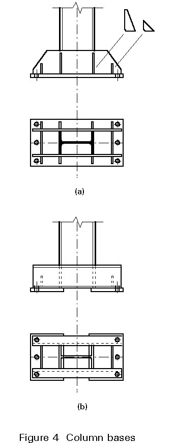
By comparison, the base detail (b) using channels would probably be longer with thicker base plates but the number of components is reduced to six and workmanship is drastically cut down. Note also that the inner edge of the two base plates is welded to the column flange eliminating any need for separate stiffeners.
Multi-storey Columns (Figure 5): Based on the philosophy of lowest weight, the columns involve three changes of section profile with two splices. It will be noted that the latter require packing pieces either laminated or solid machined to accommodate the difference in depth.
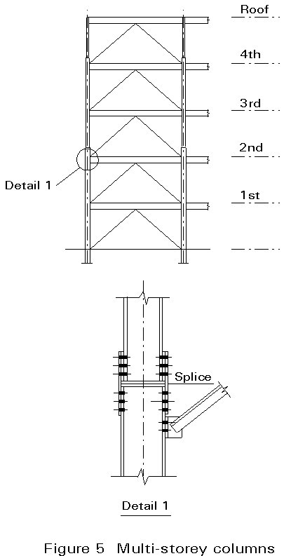
The saving in material costs by reducing the shaft above the 4th floor will be overtaken by the cost of the splice and, if the total material requirement is less than 20 tonnes, further costs will be incurred by quantity premiums on the basic rate.
The change in section depth also varies the geometry and therefore the lengths of the bracing members will vary with consequent adjustment to the skew of the end connections.
Consider the column shaft from ground to 2nd floor. Clearly the loads will be greatest here. A possibility is to investigate the use of high strength steel to match the upper section in low strength steel. Although high strength steel is more expensive, the result will be consistency of details, beam lengths and connections throughout.
Finally, it should be noted that the bracing connection is attached to the bracing member rather than the column. The benefits are as follows:
Lattice Trusses (Figure 6): Whilst there may be sound reasons for adopting bolted joints, a variety of differently shaped gusset plates are required. They all have to be punched or drilled in addition to the framing members and then individually bolted up.
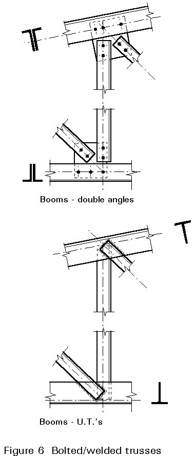
Because the inside faces of the boom members will become permanently inaccessible, these components and the gussets would need to be painted individually in advance of assembly. This work is expensive and disruptive. Therefore, although the material cost of T-sections is up to 20% higher than angles, the welded truss may still prove to be a cheaper proposition, except for girders with fairly short spans.
Whilst steelwork erection may be regarded as the final stage of fabrication, it differs from the latter in two principal ways: firstly, there is the added dimension of height and the time occupied by vertical movement of materials, equipment and labour; secondly, the fact that work has to be carried out in the open means that progress may be hampered by adverse weather.
By its nature, work done on site can become unduly expensive. The primary aim of the programme should be to minimise costs by condensing the time scale realistically. Options and alternatives need to be carefully examined at the preliminary design stage otherwise the scope for reducing the time scale may be unduly restricted.
Clearly the significance of the various issues will vary according to the type of building and any limitations which the site and its environment may impose. Even when structures possess marked similarities, different erection methods and procedures may need to be adopted. For this reason, only the broad principles concerning erection can be stated.
Invariably, erection of structural steelwork has to be closely integrated with other major trades such as flooring, cladding and services. Operations on site where there may be competition for limited resources, are potentially difficult to control. A far-sighted strategy has to be developed and maintained.
Key objectives and, most importantly, starting and finishing dates must be clearly established and progress reviewed on a regular basis. Failure to meet commitments can result in substantial cost penalties. Further complications may easily arise which are totally disproportionate to the cause.
The maximum size and weight of the various steel members which can be delivered may be restricted on a site with limited and restricted access.
Narrow streets in a busy town centre may cause difficulties with space to manoeuvre. Waiting time to off-load may also be restricted to specific periods. Matters of this kind must be investigated well in advance and decisions made accordingly.
Within site, movement may often be hampered by a variety of obstructions such as scaffolding, shoring, pile caps, excavation, and so on. Service roads and off-loading areas need to be hard cored and adequately drained to support heavy vehicles during the severest winter conditions. The steelwork has to be erected in the general sequence determined by the construction programme. Each consignment of steel has to be strictly regulated to this timetable. Whilst in some instances, a few key components can be lifted directly from the vehicle into position, most of the material will need to be off-loaded and stacked temporarily until needed.
The area of the site allocated for this purpose has to be orderly and well managed, particularly where space is limited. To compensate for minor interruptions in delivery, for example due to traffic delays, a small buffer stock is usually held in reserve.
Space is also required for laying material out and for assembly of frames or girders prior to hoisting into position.
Before commencement of erection, the plan position and level of the column bases should be verified by the erection contractor. This needs to be carried out as soon as possible to ensure that any errors can be corrected in good time or, at least, alternative measures approved and introduced.
Checks should include not only the centres of the foundation bolts relative to the reference grid lines, but also the projection of the bolts above the base level.
To compensate for minor discrepancies, a limited amount of deviation of the column from its true vertical and horizontal position is provided for by the grout space under the baseplate and by leaving a movement pocket around each bolt during pouring of the concrete. Normally this will allow latitude of about ±25mm in any direction.
Steel erection may appear to be a series of distinct operations when in reality they overlap and merge. Nevertheless, each complete stage of the work has to follow a methodical routine which consists of:
Because minor dimensional inaccuracies can accumulate during fabrication and setting out, it would be impractical to complete the entire structure before compensating for these by adjustment. The work is therefore sub-divided into a number of phases which may be controlled by shape or simply by an appropriate number of bays or storeys. For stability, each phase relies upon some form of restraint to create a local box effect. This effect may be achieved in various ways, such as employment of temporary or permanent diagonal bracing.
Initially, end connections and base anchorages are only secured temporarily. After completion of plumbing, lining and levelling, all connections are then made permanent by tightening up all nuts or inserting any bolts initially omitted to assist adjustment. This process allows substantial areas to be released quickly for grouting and following trades are able to proceed much earlier than would otherwise be possible.
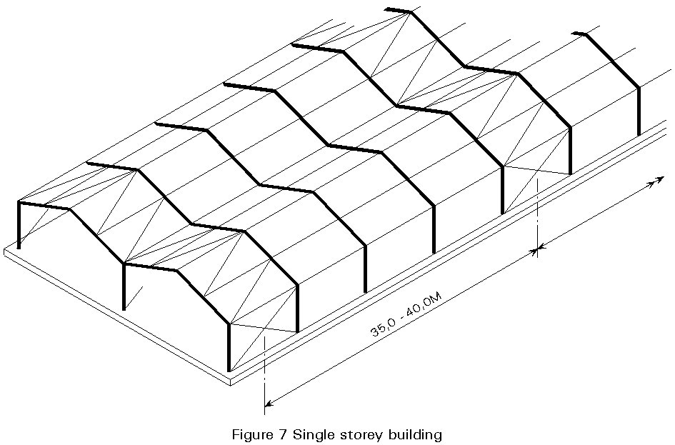
Under normal circumstances, single-storey buildings are quickly and easily erected. A high proportion of industrial buildings are rigid jointed. It is common practice to bolt, assemble or weld these joints on the ground and then lift the complete frame upright using a mobile crane.
Lattice girders and trusses are also erected in a similar manner but temporary stiffening may be required to prevent lateral buckling. Care should also be taken, by provision of lifting eyes or similar at specific positions, to ensure that slender members are not subjected to undue compressive stresses.
Ideally, erection should commence at an end which is permanently braced. When this is not possible, temporary bracings should be provided at regular intervals as a safeguard against collapse or deformation (Figure 7).
Space frames are designed to span in two directions. Because of the number of connections required, it is much more economical to assemble the modules at ground level where the joints are readily accessible and then hoist the complete framework. Two or possibly four cranes may be needed depending on the size of the building. Meticulous co-ordination is essential.
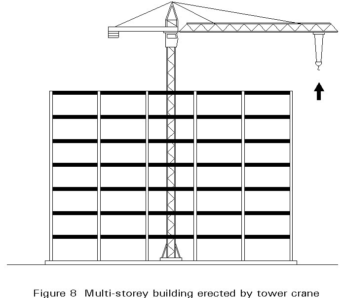
In most cases, multi-storey buildings are erected storey by storey enabling the lower floors to be completed earlier, offering access, overhead safety and weather protection. Depending upon the site, a single tower crane may be the sole lifting facility. In this case use of the crane has to be shared between a number of sub-contractors, thereby limiting available "hook" time for any given trade.
Since the position of a tower crane is fixed (Figure 8), it is completely independent of any obstructions, such as basements or ground slabs, which could deny access to a mobile crane. This independence allows useful freedom in overall planning. However, the fixed location also means a fixed arc of lifting capacity where the load will be minimum at the greatest reach. As a result the steelwork may have to be provided with site splices simply to keep the weight of the components within such limits.
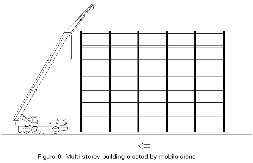
One of the major virtues of a mobile crane (Figure 9) is its flexibility and independence which enables it to keep moving with the flow of the work. These cranes are generally fitted with telescopic jibs which allow then to become operational very quickly. The vehicles are stabilised during lifting by extended outriggers equipped with levelling jacks.
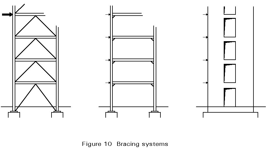
Whilst permanent stability in the completed building may be introduced, in a number of ways, including braced bays, rigid joints and stiff service cores (Figure 10) and via diaphragm action of the floors, stability must also be ensured throughout the entire construction programme. It may therefore be necessary to install temporary bracings solely for this purpose, which must not be removed until the permanent system has been provided and has become effective.
The rate of steelwork erection is governed by a wide range of factors some of which are beyond the influence of the design engineer. The factors which he can control include:
Simple connections for shear force are straightforward and employ Grade 4.6 or 8.8 bolts. The bolt diameter should be selected with a degree of care. For example, whilst a single M30 bolt has more than twice the shear capacity of two M20's, the effort required to tighten an M30 bolt is some 3½ times greater. An M20 bolt can be tightened without difficulty using ordinary hand tools, a considerable advantage when working at height.
Joints which are required to transmit bending moments are inherently more robust and may require stiffening ribs and haunches; if this is the case careful attention is required to ensure access for the bolts. For such applications pre-tensioned bolts are often used. They are normally tightened to a minimum torque using a power operated wrench.
Compared to bolting, the site welding of joints is time-consuming and expensive for conventional structures. There may be occasions, however, when site welding is the only realistic way to form a joint, as, for example, in alterations or remedial work. In this case, joint preparation, fitting, inspection and the provision of purpose made enclosures (for access and weather protection) are additional cost factors that must be taken into account.
As a rough guide, about 50% of erection man hours are occupied with lining, levelling, plumbing and final bolting and the remainder of the time is spent hoisting members into position. However, in suitable cases, beam and column elements may be pre-assembled at ground level and lifted directly on to their foundations.
The erection of a building framework is potentially hazardous. Many serious and fatal accidents occur each year on construction sites and most of these are caused by falling from, or whilst gaining access to, heights; handling, lifting and moving materials, however, are also hazardous.
Risks can be minimised considerably by measures such as adequate provision for stability throughout construction, accessibility of splices and connections, guard rails and attachments for safety harnesses and so on.
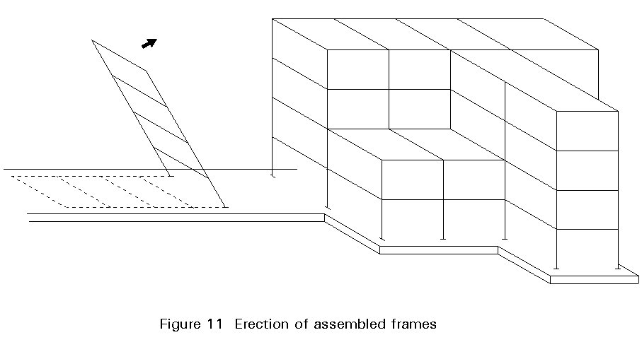
In addition, safety, need not be compromised on grounds of cost. For example, it will prove cheaper to assemble frames at ground level (Figure 11) rather than bolt them together in mid-air. Metal decked floor systems are not only economical but offer rapid access for all trades whilst providing overhead protection. Safer access is also promoted by the immediate provision of steel stair flights at each floor level as steelwork erection proceeds.
Current and future legislation may place greater responsibilities upon the design engineer because of the influence of design and details on the method and sequence of erection.
GS 28/1 Initial Planning and Design, 1984.
GS 28/2 Site Management and Procedures, 1985.
GS 28/3 Working Places and Access, 1986.
GS 28/4 Legislation and Training, 1986.