ESDEP WG 3
FABRICATION AND ERECTION
To present an overall view of the implications of making joints by welding.
Lectures 3.1: General Fabrication of Steel Structures
Lecture 3.4: Welding Processes
This lecture describes the basic principles involved in making a welded joint. It discusses the structure and properties of both the weld metal and the heat affected zone. It explains the necessity for edge preparations when butt welding, and gives examples of the types used. It outlines how the welding procedure can be varied to meet the needs of the particular joint being made.
MAG Metal Active Gas Welding (sometimes referred to as MIG Metal Inert Gas Welding)
MMA Manual Metal Arc Welding
SAW Submerged Arc Welding
HAZ Heat Affected Zone
Welding offers a means of making continuous, load bearing, metallic joints between the components of a structure.
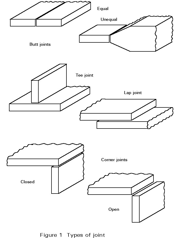
In structural work, a variety of welded joints are used; these can all be made up from the basic configurations shown in Figure 1, which are classified as follows:
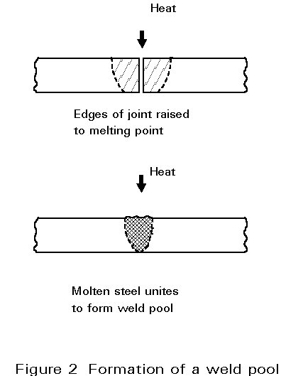
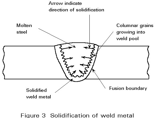
As illustrated in Figure 2, a welded joint is made by fusing (melting) the steel plates or sections (the parent metal) along the line of the joint. The metal melted from each member at the joint unites in a pool of molten metal which bridges the interface. As the pool cools, molten metal at the fusion boundary solidifies, forming a solid bond with the parent metal, see Figure 3. When the solidification is complete, there is continuity of metal through the joint.
Two types of weld are in common use: butt welds and fillet welds. In the former the weld metal is generally contained within the profiles of the welded elements; in the latter, deposited weld metal is external to the profile of the welded elements.
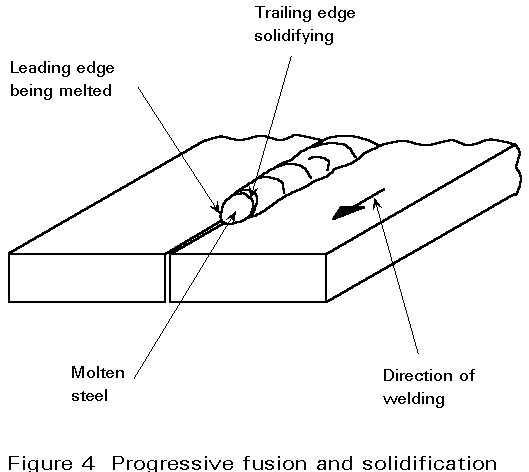
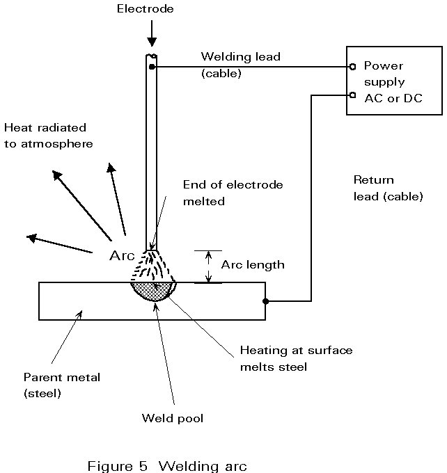
Obviously the complete length of joint cannot be melted simultaneously. In practice a heat source is used to melt a small area and is then moved along the joint line, progressively fusing the parent metal at the leading edge of the weld pool, as shown in Figure 4. At the same time, the metal at the trailing edge of the pool solidifies. The most commonly used heat source, in structural work, is a low voltage (15 to 35 volt), high current (50 to 1000 amp) arc. As shown diagrammatically in Figure 5, the arc operates between the end of a steel electrode (rod) and the work piece. It melts both the parent metal and the electrode; molten metal from the electrode is thereby added to the weld pool.
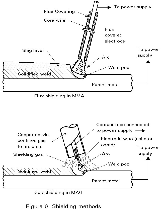
The molten steel in the pool will readily absorb oxygen and nitrogen from the air, which could lead to porosity in the solidified weld and possibly to metallurgical problems. Figure 6 shows how this is avoided by covering the pool with a molten flux, as in Manual Metal Arc (MMA) and Submerged Arc Welding (SAW), or by replacing the air around the arc by a non-reactive gas, as in Metal Active Gas (MAG) Welding or cored wire welding.
The solidified weld metal has a cast structure and has properties characteristic of cast steel, i.e. higher ratio of yield to ultimate strength than structural steel. The weld metal is a mixture of parent metal and steel melted from the electrode. In structural work the composition of the electrode is usually chosen so that the resultant weld metal is stronger than the connected elements. Occasionally, specific conditions may override this chocie. For example, when joining stainless steel to carbon-manganese steel, a highly alloyed electrode must be used to avoid cracking in the weld metal.
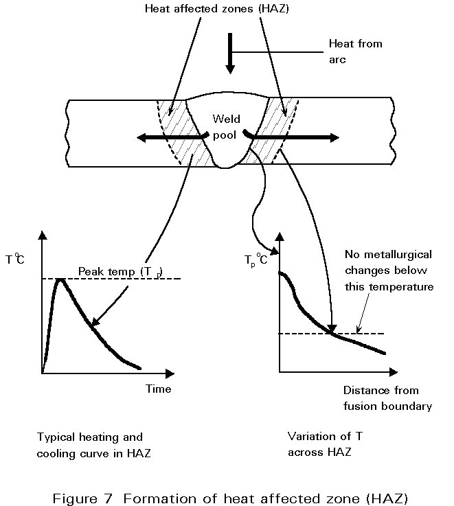
When the weld pool is cooling and solidifying, the majority of the heat flows through the parent metal alongside the joint. The steel is thus subjected to heating and cooling cycles similar to those experienced in heat treatment practice. As shown in Figure 7, the structure of the steel will be changed in this region (called the heat affected zone, HAZ). This must be taken into account in the design in terms of notch toughness (Charpy value), etc.
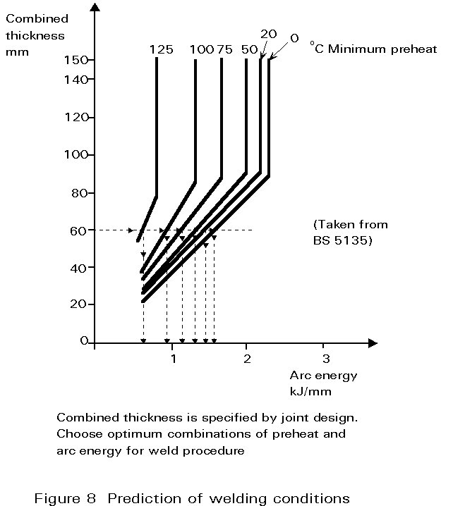
The structure of the HAZ will be controlled by:
In turn the cooling rate is determined by:
A method of determining the interaction of these factors in relation to the avoidance of cracks in the HAZ is given in the sample chart shown in Figure 8.
In addition to its effect on the cooling rate, preheat is used to:
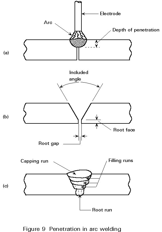
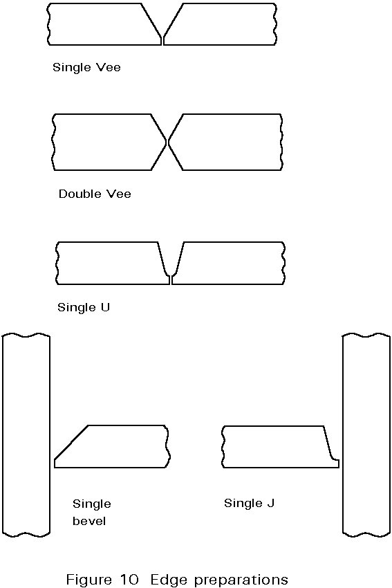
For square edge preparations the depth of melting into the plate is called the Depth of Penetration, see Figure 9a. As a very rough guide, the penetration is about 1mm per 100 amp. In manual welding the current is usually not more than 350 amp; more commonly 150-200 amp. This means that the edges of the plate must be cut back along the joint line for continuity through the thickness to be achieved (Figure 9b). The groove so formed is then filled with metal melted from the electrode (Figure 9c). Various edge profiles are used and are illustrated in Figure 10; the edges may be planed, sawn, guillotined or flame cut.
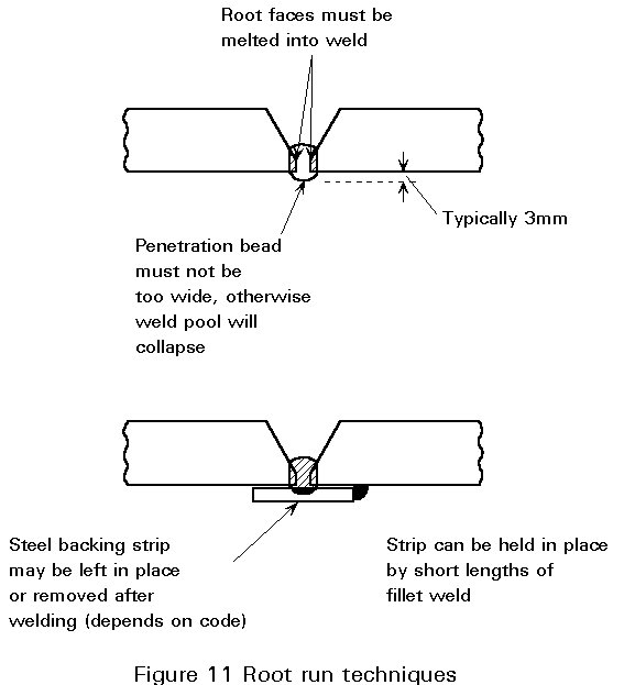
The first run to be deposited in the bottom of the groove is called the root run. The root faces must be melted to ensure good penetration, but at the same time the weld pool must be controlled to avoid collapse, as seen in Figure 11. This task requires considerable skill. The difficulties can be eased by using a backing strip.
The choice of edge preparation depends on:
The term welding procedure is used to describe the complete process involved in making a weld. It covers choice of electrode, edge preparation, preheat, welding parameters (voltage, current and travel speed), welding position, number of weld runs to fill the groove, and post-weld treatments, e.g. grinding or heat treatment. Welding procedures may be devised to meet various needs, e.g. to minimise costs, control distortion, avoid defects or achieve good impact properties. Specific aspects of the weld procedure are worth detailed comment.
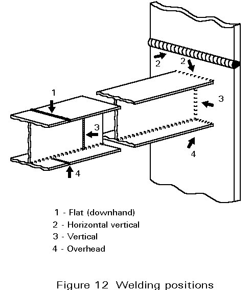
The current controls heat input. The minimum value is fixed by the need to fuse the plate and to keep the arc stable; the specified minimum, however, may be higher to avoid HAZ cracks. The maximum current depends on operating conditions. Usually, as high a current as possible is used to achieve faster welding, and hence lower costs. The use of maximum current may be restricted by position; in the overhead position, for example, currents above 160 amps cannot be used. High currents usually give low impact properties. Note that the current used is chosen to match the electrode diameter.
The effect of position on current is noted above. Welding in the overhead position requires greater skill to avoid defects, such as poor profile, and should only be used when absolutely necessary. Vertical welding is slower than welding in the flat position but requires less skill than the overhead position.
If on site welding is necessary the following points must be considered:
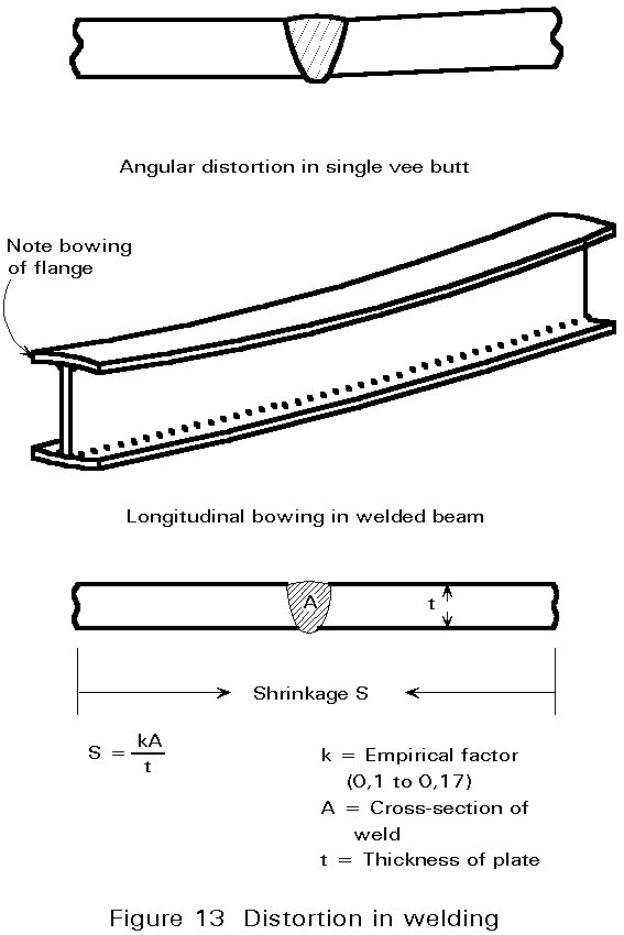
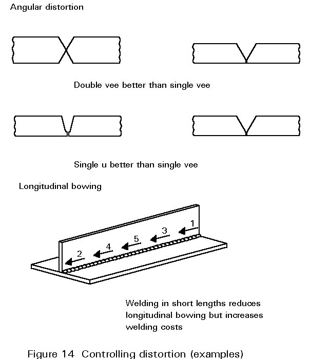
During cooling, the hot metal in the weld zone contracts, causing the joint to shrink. The contraction is restrained by the cold metal surrounding the joint; stresses are set up which, being in excess of the yield stress, produce plastic deformation. This can lead to the distortion or buckling shown in Figure 13. Distortion can be reduced by choice of edge preparation and weld procedure; examples are shown in Figure 14.
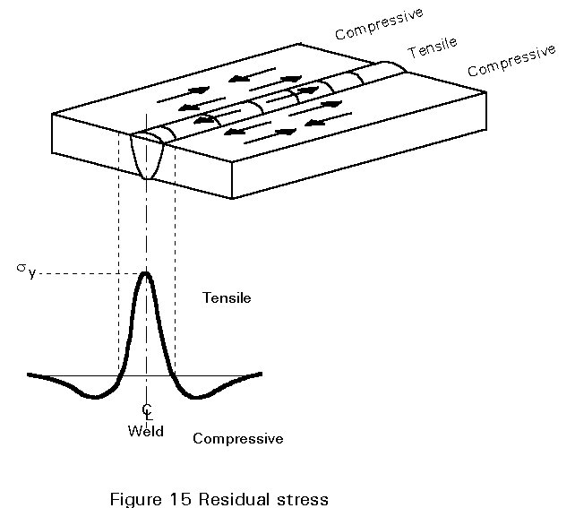
When the plastic deformation has ceased, the joint is left with the residual stress pattern of Figure 15 with tension in the weld metal and HAZ, and compression in the surrounding steel. The significance of these residual stresses is discussed in other lectures.
× details of joints and welds.
× strength of welded joints.
× effects of welding on metallurgical structures, heat affected zones, HAZ cracking.
× edge preparation.
× welding positions - definitions and comments.
× formation of a weld.
× types of heat source.
× strength of welded joints.
× effects of welding on metallurgical structure, heat affected zones, HAZ cracking.
× edge preparation.
× comments on residual stresses.
× control of distortion.
× effects of welding on metallurgical structure, heat affected zones, HAZ cracking.
× control of distortion.
Steel Construction Institute - Publication No 014.