ESDEP WG 3
FABRICATION AND ERECTION
To give a brief outline of the fabrication process for steel structures; to identify the factors affecting manufacturing costs and to stress the importance of the designer considering the fabrication process when preparing the design.
None are essential.
The following lectures might be helpful:
Lecture 2.1: Characteristics of Iron-Carbon Alloys
Lecture 2.2: Manufacturing and Forming Processes
Lectures 2.3: Engineering Properties of Metals
Lecture 2.4: Steel Grades and Qualities
Lecture 2.5: Selection of Steel Quality
Lecture 3.3: Principles of Welding
Lecture 3.4: Welding Processes
Lecture 3.5: Fabrication/Erection of Buildings
Lecture 4A.1: General Corrosion
Lecture 15A.8: Offshore: Fabrication
Lecture 15B.12: Introduction to Bridge Construction
The lecture gives a brief summary of the forms of contract and organisation used for the fabrication of steel structures. It reviews fabrication processes with brief descriptions of the main operations.
The objective of this lecture is to give an insight into the fabrication aspects of steel structures. Optimum design of steel structures can only be achieved if fabrication and erection are considered together with the functional, architectural and structural requirements.
To minimize total costs and optimise the design of the steel structure, it is important that the various disciplines involved work in a coordinated way as a project team during the various stages.
Fabrication costs do not depend only on the fabrication itself but are also influenced by the contract scope, contracting procedures and organisation. Costs are very sensitive to the labour involved in the fabrication. Good design concentrates on minimising material handling and preparation; in this regard it should be noted that fabrication procedures and sequencing may be influenced by the protection required to the steelwork. Careful attention should also be given to other aspects such as material characteristics, distortions and tolerances.
Both the form of contract and of the organisation depend heavily on the project, the client and the contractor involved. It is common practice for the fabrication company to enter into a contract which involves fabrication, erection and the preparation of the detail drawings; this can prove most competitive since the fabrication costs of a steel structure are substantially influenced by the cost-consciousness of the detail-engineering.
Major constructions, such as high-rise buildings, bridges, and offshore structures, are usually designed by a specialist consulting engineering practice under a separate contract; however, for commonplace structures (portal frames, etc.) it is not unusual that the total design is undertaken by the contractor in a package deal with the client.
After receipt of the order and agreement of terms, copies of the principal documents are passed on to the Drawing Office. These documents usually include:
The success of any contract generally depends on compliance with the requirements of the project programme; deviations from the programme can have very serious effects on costs; delays can be traumatic for the other participating trades and subsequently for the client.
The programme is usually made out in bar-line format and based on network techniques, including critical path analysis.
Essential elements are:
Each element is planned to a set timescale, and co-ordinated with parallel actions from other contracts occurring during the same period. If the erection programme imposes demands for shop fabrication in excess of the fabricator's capacity, then sub-letting of work will be necessary, coupled with the requisite QA- and QC-assessment.
The drawings can be produced expeditiously and economically only if the consulting engineer provides all necessary information concerning the geometry of the structure, member sizes, forces and moments in connections. Without the relevant information there will be very costly delays not only in the Drawing Office, but in the whole production chain. Extra costs will be incurred by variations to the design after the drawings have been completed. Even more significantly, extra costs will arise if modifications have to be made to work in the fabrication shop; alterations to work on site are generally very costly, particularly if programme delays result.
The production of the drawings will include three phases:
The time and cost involved in preparing drawings will largely depend upon the degree of repetition and the complexity of the design; careful consideration of these matters prior to starting setting out and detail work should result in drawings that, efficiently and unambiguously, communicate the structural requirements to the workshop operatives and the site erection team.
Work stations equipped with modern computer graphics, when used by trained draughtsmen, can result in higher rates of drawing production. They can also result in a higher quality of drawing with modifications being more easily incorporated. Long-distance transfer by telephone is possible. Automatic listings of materials and tapes for numerically controlled (NC) fabrication may also be produced advantageously by these facilities.
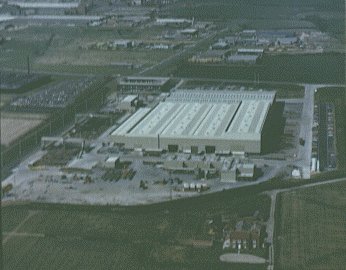
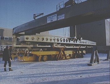
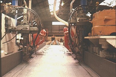
Fabricators range from small general firms to large specialised producers with different facilities at their disposal. In either case the fabrication must always be organised in such a way that the material will pass through a one-way system from receipt to final despatch (Slide 1). A flow chart, as indicated in Slide 2, shows the main areas of activity in a modern fabrication shop; the specific activities for a simple steel beam can also be organised as a production line (Slide 3).
Slide 1
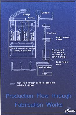
Slide 2
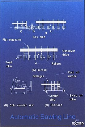
Slide 3
Most fabrication shops are equipped with overhead travelling cranes, sometimes remotely controlled from the shop floor. Mechanised conveyor systems are common in the larger shops. They can greatly reduce handling costs.
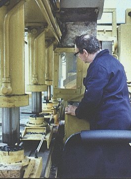
Special facilities must be provided for the storage of flammable materials; pipelines for gas and oxygen must be installed. Welding areas require a heavy power supply and screening to protect eyes from ultraviolet glare. Some operations are very dusty and noisy, such as mechanical chipping and arc gouging. Where possible, they should be separated, therefore, from the other production areas.
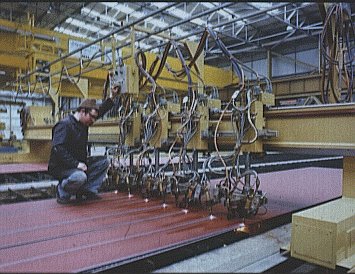
Material is taken into temporary stock in such a way that it can be easily identified and moved. Some companies stack the material for easy access and move it by using cranes equipped with chains and hooks. Other companies use a high degree of automation in their material handling, using cranes on conveyors with magnetic lifting devices; Slide 4, for example, shows a travelling Goliath Magnet Crane with the capacity to lift both plates and sections (Slide 5 also shows a similar operation). Computerised records hold details of member sizes, lengths, weights and steel quality, all related to an identification mark.
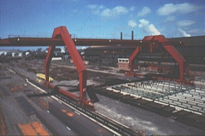
Slide 4
Slide 5
When required, the steel is shot blasted in a separate location, either by hand or automatically. Sometimes the automatic installations can sense the size of the members. Paint-spraying (done either by hand or automatically) may follow directly after blast cleaning, depending on the production programme; if, for example, welding is required then painting will take place after fabrication.
Steel may be marked directly by hand with scribe lines and hole centres; nowadays, however, in most shops pre-programmed automatic plant is in use. Traditionally, full-sized templates, made of timber or heavy cardboard, were used to mark the steel for cutting and for centre popping where holes were to be drilled.
Occasionally a drilled and bushed template, made of steel, would be used for mass-produced items in order to avoid the template wearing out. Templates are still being used, particularly for small plate fittings and gussets, but the templates themselves are made by automatic fabrication methods after plotting in the Drawing Office using computer work stations. These techniques greatly reducing the work of the traditional skilled template maker.
The rolled sections are in most cases sawn to length, the other options being mechanical cutting or flame burning. Three types of saws are available to the fabricator:
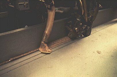
By far the most popular choice is the circular cold saw, as its productivity is better than that of the band saw or the hack saw. These saws are, in many cases, integrated in automatic sawing lines, equipped with mechanised longitudinal and transverse conveyors and measuring devices, as shown in Slides 6 and 7.
Slide 6
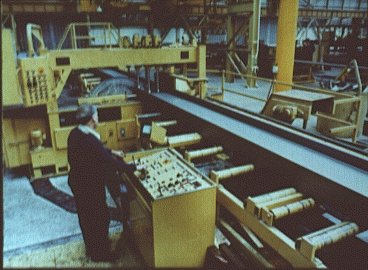
Slide 7
A saw can perform within an accuracy of a fraction of a millimetre on length and within a squareness of 0,2% of the depth of the cut. The most accurate type is equipped with a swivelling arm enabling the blade to descend onto the bar. The blade speed adjusts itself automatically on its way through the work piece. A fully automated saw system will be operated through a computer program.
The traditional method of drilling involves three operations:
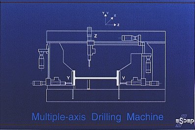
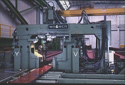
The better equipped fabrication shops nowadays have automatic beam-line systems (Slide 8) which are generally linked to the conveyors of the sawing line. The beam (Slide 9) moves by longitudinal conveyors along the Y-axis, denoted V and X for each flange, while the web drilling heads move along the Z-axis.
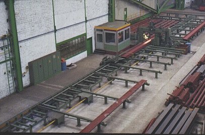
Slide 8
Slide 9
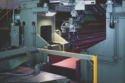
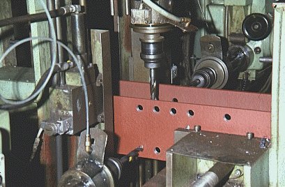
Like the sawing line, this system is controlled by computer programs; some machines are equipped with multiple drilling heads enabling them to drill several holes simultaneously in each axis (Slides 10 - 12).
Slide 10
Slide 11
Slide 12
New twist drills are currently available which are capable of higher speeds and greater efficiency as follows:
Cropping shears can be used for cutting small sections of limited thickness.
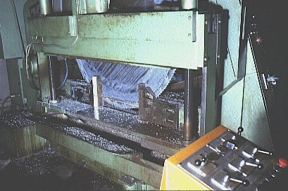
Guillotines can be used for shearing plates up to 25 mm thick but the plate will usually distort by the high pressure contact with the bottom blade; these, therefore, may only be used where the specification allows. New punching machines, however, operating at high speeds, will induce less distortion of the material.
Punching holes in steelwork is much faster, and therefore less costly, than drilling; its use, however, is generally limited to predominantly statically loaded structures with limited thickness, or to secondary members, unless HSFG bolted connections are used or the holes are reamed out to a larger size. The maximum thickness where punching is applicable depends on the material grade and quality.
Bevelling and shaping of plates by flame cutting is general practice in most fabrication shops. Oxygen and propane are usually stored in bulk in areas outside and supplied to the shopfloor in pipelines. The equipment for flame cutting ranges from the simple hand-held torch to multi-torch, numerically controlled, profiling machines (Slide 13). For wider plates several heads can be arranged in order to ensure that equal heat is applied to both edges, thereby avoiding distortion. The cutting carriage can even be provided with three cutting heads in order to produce double-bevel edges.
Slide 13
Single head machines can be operated by an optical controlling head, following a one-in-ten or full size outline, drawn on paper. Profile cutting is often performed by numerically controlled machines which also have the capacity to mark hole positions and hardstamp identification marks.
For accelerated cutting speeds, where edge hardness is not considered detrimental, other methods, like plasma cutting under water or under an inert powder, are available. Laser cutting is just starting to come into use, but is, for the time being, restricted to thin plates; the resulting edge hardness, however, makes it unsuitable for some applications.
The fabricator must be aware that flame cutting will always result in shrinkage, for similar reasons as for welding.
Symmetrical burning of plates limits distortion. Machining of one side will result in deformation due to the resulting residual stress.
For the modern fabricator the most important application of plate forming and pressing is to add to the available range of rolled sections. The trapezoidal shaped trough (Slide 14), used to stiffen bridge decks, is a very good example. Other examples are the circular sections of larger than standard dimensions (Slide 15).
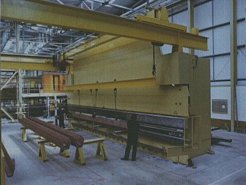
Slide 14
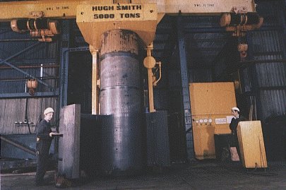
Slide 15
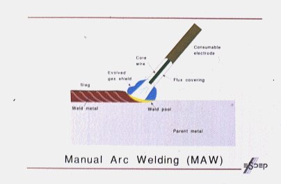
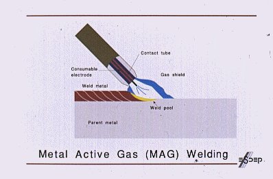
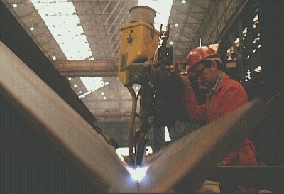
Three welding processes are most commonly used in modern fabrication shops:
Slide 16
Slide 17
Slide 18
Because a full penetration weld is more difficult to make than a full strength weld, full penetration welds should only be used where necessary, such as in connections where high fatigue stresses can occur. Good welding design reflects the economies and advantages of different types of weld by choosing types appropriate to the needs of the design.
The full strength weld is easy to achieve using fillet welds; full penetration welds, however, without inclusions at the centre, can only be achieved by extensive back gouging prior to welding the reverse side. The risk of faults in full penetration welds is much greater and control of distortion more difficult.
Control of distortion is achieved by prestressing the member before welding, or by a balanced application of heat on each side of the neutral axis of the section. Allowance must also be made for overall contraction due to welding. The quality of the fitting-up is very important as any excess gap will affect the distortion and increase the shrinkage.
Maintaining the quality of the weld at the end of the run is difficult. The problem in butt welds can be tackled by tacking short run-on and run-off plates on each side which are removed after completion of the weld.
Welding procedures are the responsibility of the Welding Engineer, who will produce a procedure sheet for each weld. He will also make sure that the welder is qualified to the required standard.
He may also supervise any non-destructive testing (NDT) which may be undertaken by radiographic, ultrasonic, magnetic particle or dye penetrant means.
The welded plate girder forms a natural addition to the range of rolled sections available. The typical production sequence is as follows:
Slide 19
Slide 20
Simultaneous welding of the flanges will reduce distortion.
Most fabrication shops are equipped with facilities for edge planing, for end milling and for surface machining of plate (Slide 21).
Slide 21
Unacceptable levels of hardness at the edge of the plate, often caused by burning, can be removed by planing.
End planing of members is used to get a higher standard of squareness than can be achieved by sawing. Optical laserbeam methods are used to align the axis of the member to the cutting head.
Surface machining is only necessary for special bearing surfaces and sometimes for the slab base plates of columns.
Modern fabrication shops have accurate dimensional control over fabricated sections and have no problems in cutting the rolled material to length. The main problem is coping with the deviations in the sections and plates received from the steelmills. Euronorm (CEN) and ISO standards give dimensional tolerances for rolled sections, plates and flats, hollow sections and angles respectively. The fabricator will use bending rolls to straighten the material and to "square" flanges of beam sections at critical connection points. As already mentioned, the control of distortion due to welding during assembly is the important factor in producing dimensional accuracy in welded sections.
The details and the connections must be designed in such a way that the tolerances will be met within the limits of good workmanship. An example is given in Slide 22.
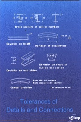
Slide 22
It is sometimes necessary to "prove" the dimensional qualities of the product by a trial erection of one section of the structure in the fabricator's works.
Parts of bridge structures, particularly those bound for overseas locations, and structures for the support of intricate industrial plant are likely candidates.
Trial erection is expensive and should be avoided where possible by incorporating methods of site adjustment into the design and by optimum control of measurements.
Quality Control should commence with the designer and continue through the preparation of drawings and material procurement; maintaining the quality during the entire production process will depend heavily on the fabrication details and on the material obtained.
The larger fabricators have their own Quality Control Department, which will create and maintain a QC-manual, describing the method of operation throughout the fabrication process. The Quality Control Department will liaise with the shop management to make sure that all workers have the skill required for the job on hand and that welders are qualified to undertake the prescribed welding procedures.
Regular checks are necessary to ensure that:
Close liaison should always be maintained between the QC staff and the Drawing Office.