ESDEP WG 11
CONNECTION DESIGN: STATIC LOADING
To describe the influence of particular aspects on the design of bolted connections.
Lecture 1B.1: Process of Design
Lecture 2.4: Steel Grades and Qualities
Lectures 3.2: Erection
Lecture 11.1.1: Connections in Buildings
Lectures 11.3.1 & 11.3.2: Bolted Connections
Lecture 11.4: Analysis of Connections
Lecture 12.6: Fatigue Behaviour of Bolted Joints
Non-conventional but practical situations occurring in bolted connections are discussed. The following problems are considered:
NOTATION
A Area of the shank of a bolt [mm2]
As Stress area [mm2]
d Nominal diameter of the bolt (shank) [mm]
Fs.Rd Design slip resistance [N]
Fp Preload of a bolt [N]
Fu,b Nominal tensile strength of a bolt [N/mm2]
ks Reduction coefficient of the slip factors
n Number of friction faces
g
ms Partial safety factor for a slip resistant boltThe resistance of a connection should be determined on the basis of the resistance of the individual fasteners.
Bolts for structural steelwork are available in various sizes and grades. Non-preloaded bolts are used for the majority of structures. Where special requirements on the stiffness, the prevention of slip during load reversal or fatigue are to be met, high strength friction grip (HSFG) bolts may be used.
The resistance of a (non-preloaded) bearing connection depends on the shear resistance of the bolt and on the bearing resistance of the plates. If the bearing resistance of the plates is lower than the shear resistance of the bolt, the deformation capacity of the joint is large. This is particularly important in long joints and where inaccuracies exist in the hole patterns.
The shear resistance of HSFG bolts is sensitive to the coefficient of friction m and the applied preload.
Lectures 11.3.1 and 11.3.2 describe standard connections with the types of bolts mentioned above.
Due to practical requirements it is often necessary to use different constructional designs. In addition there may be a combination of forces on the connections making it difficult to evaluate the stresses in the bolts.
Particular aspects of bolted connection behaviour and design are reviewed herein.
Restricting the nominal hole diameter to the values given in Lecture 11.3.1 (for example, 2mm in excess of the nominal bolt diameter) can impose rigid alignment conditions between structural members, particularly in large joints. Sometimes erection problems occur when the holes in the plate material do not line up properly. Occasionally, steel fabricators must preassemble structures to ensure that the joint will align properly during erection. With a larger hole size, it is possible to eliminate the preassembly process and save time and money.
An average hole provides the same clearance in all directions to meet tolerances during erection. However, if an adjustment is needed in a particular direction, slotted holes can be used. Slotted holes are identified by their parallel or transverse alignment with respect to the direction of the applied load.
When oversize and slotted holes are used, additional plate material is removed from the vicinity of high clamping forces. The influence of this condition on the behaviour of connections with preloaded bolts has been investigated experimentally [1]. The effect of oversize and slotted holes on such factors as the loss in bolt tension after installation and the slip resistance has been examined.
The use of oversize or slotted holes reduces slightly the mean clamping force in the fasteners. This reduction is thought to result from plastic flow in the steel plates under the head of the bolt and the nut. The influence of plastic flow can be reduced by using hardened washers. The reduction of clamping force influences also the slip factors. The combined effect of the change of slip factor and reduction of the clamping force is estimated to cause a 15% reduction in slip resistance for oversize and short slotted holes and a 30% reduction for long slotted holes.
The design formulae for slip-resistant joints reflect the reduced slip resistance by introducing a reduction factor ks.
The design slip resistance of a preloaded high strength friction grip bolt is therefore given by:
Fs,Rd = [(ksm)n/gms]. Fp.Cd
(see Lecture 11.3.2 for the design slip resistance in a connection where the holes have nominal clearance).
The coefficient of reduction ks is equal to 0,85 for oversize and short slotted holes and to 0,70 for long slotted holes.
The nominal sizes of short slotted holes for slip resistant connections may not be greater than:
where d is the nominal bolt diameter in mm.
The nominal sizes of long slotted holes for slip resistant connections may not be greater than:
Long slots in an outer ply must be covered by cover plates of appropriate dimensions and thickness (see above). The holes in the cover plates may not be larger than standard holes.
The sizes required for long slotted holes for movement joints have to be specified. Slots in an outer ply must be covered by cover plates of appropriate dimensions and thickness (see above).
In those cases where oversize or slotted holes are used with non-preloaded bolts, then it is customary to assume no reduction in design resistances due to the oversize effects.
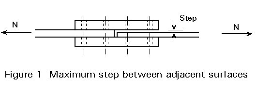
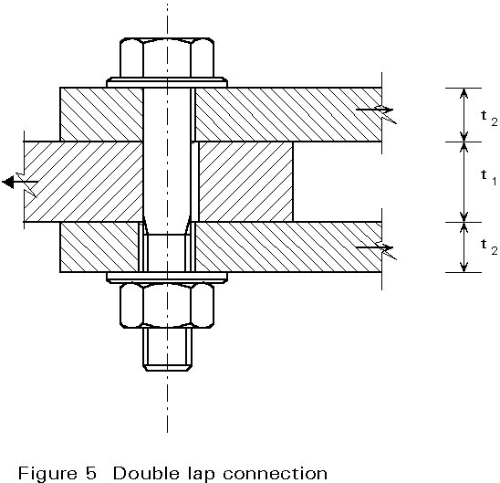
The maximum step between adjacent surfaces in a joint may not exceed 2mm in order to avoid any reduction of the resistance of the connection (Figure 1). When using preloaded bolts, the possible effects of lack of fit have to be considered and smaller tolerances could be imposed. If it is not possible to adopt smaller tolerances, packing plates should be used in order to transfer properly the load across the splice. The minimum thickness of steel packing should be:
Because of practical difficulties such as the need to connect plates of different thicknesses or poor fit-up after erection on site it is sometimes necessary to insert thin steel plates to act as packs. Providing such packs are no more than a few millimetres in thickness and good contacts are ensured, then structural performance should not really be affected. Instances will arise, however, when their presence cannot be ignored at the design stage:
·
For connections made with ordinary bearing bolts the bolt shank will be subjected to an increasing degree of bending as the packing thickness increases. This is covered by EC3, in the following rule:Where bolts transmitting load in shear and bearing pass through packings of total thickness tp greater than one third of the nominal diameter d, the design shear resistance shall be reduced by the factor
![]()
·
When HSFG bolts are being used for clamping lengths greater than 10 times the bolt diameter, the parameters controlling the tightening method must be determined by tests.·
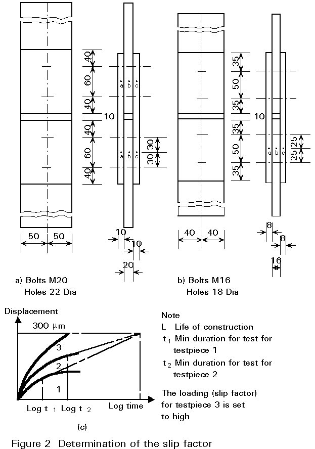
For HSFG bolts creep and relaxation effects may well be higher, leading to a larger loss of preload.The slip factor for the proposed method of surface preparation may be obtained directly from published information as explained in Lecture 11.3.2, (generally involving a surface coating). Sometimes, however it may be necessary to determine the slip factor by tests, in accordance with the following procedure [2, 3].
The calculations must in this case be based on the value reached in 95% of all tests. With a normal distribution of the results, this value corresponds to mmean times 1,64 S (S = standard deviation).
The following points must be observed when the tests are carried out:
m = Fs/4 Fp
n ³
where:
n is the necessary number of testpieces (two fastenings each) including the first tests
S is the standard deviation in first five testpieces (10 values) as a percentage of mean value.
A useful summary of slip factor test results covering a range of different surface conditions that concludes with a series of recommended factors, is available from the ECCS (4).
When the deformation of a connection under load must be very low, it is possible to use fitted bolts.
The requirements concerning fitted bolts are:
The nomenclature h11 and H11 refer to the fits relating to deviations.
An alternative to the fitted bolt is the injection bolt, i.e. bolts where the clearance between the bolt and the wall of the hole is completely filled with a two component resin (Figure 3) [7]. The bolts may or may not be pretensioned.
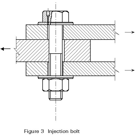
These bolts are used mainly: in new railway bridges, in heavily loaded crane runway girders and to repair riveted connections in bridges.
Injection bolts are "normal" bolts with a small hole drilled in the head (Figure 4). The dimensions of the 5,5 mm hole in the top of the head offer sufficient support for the nozzle of the injection equipment. The other part of the hole, 3,2 mm, is wide enough for injecting the resin.
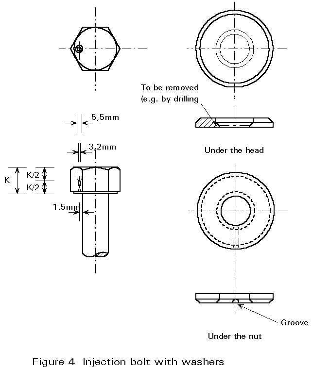
A hardened washer is placed under the head with the inside machined as shown in Figure 4. The extra space under the head facilitates the flow of the resin around the bolt, filling the clearance between the bolt and the plates completely. The inner diameter of the washer must be at least 0,5 mm larger than the diameter of the shank.
A hardened washer with a groove is placed under the nut to enable the air to escape (Figure 4). The washer must be placed with the groove at the nut side. If the plates are painted, this position will prevent the groove from being filled with paint during tightening.
The advantages of this type of bolt are:
Many systems to control the preload in bolts have been tested; the most popular are "TC bolts" and "Load Indicator washers". Their use is very simple, but the scatter of the preload magnitude is large. They represent an alternative to the direct methods described in Lecture 11.3.2.
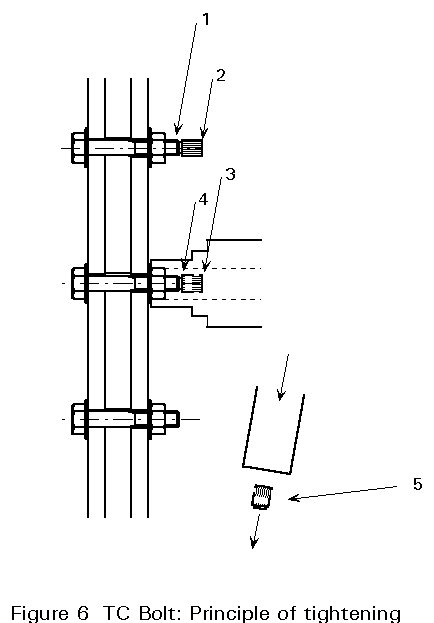
This type of bolt has the advantages:
On the other hand, the reduction in preload is rather large and tightening in two stages is not possible.
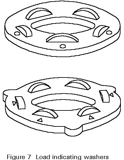
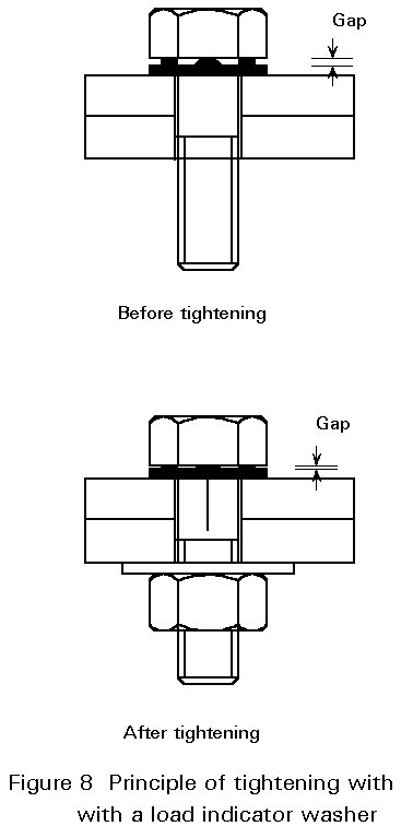
All the bolts shall be tightened in accordance with the manufacturers instructions and to the required tension indicator gap recommended by the manufacturer, as verified by calibration tests.
Tightening shall be carried out progressively from the middle of the joint to the free edges, to avoid loosening previously tightened fasteners.
Tightening to the required gap shall be carried out in two stages to ensure consistency of preloading. In the first stage 75% of the deformation of the protrusions of the tension indicator shall be reached. In the second stage of final tightening the required gap shall be reached.
The slip factor between protected plates must be determined by tests if not specified.
If the protective coating is thicker than 15 mm (hot dip galvanised plates, for example) preloaded bolts must be retightened one or two times. The best procedure is to retighten them once after 2 weeks and a second time after 3 months.
All necessary precautions shall be taken during fabrication and erection to ensure that the slip factor assumed for the calculation is reached and maintained.
At the present time, a wide range of structures are being treated with a protective surface coating to prevent corrosion and reduce maintenance costs.
To connect plates of weathering steel or plates with a protection against corrosion, zinc coated bolts (galvanised bolts) or weathering steel bolts are often used.
The zinc coating on the surface of a bolt does not affect the bolt static strength, but it adds a frictional resistance on the threads. The effect of high frictional resistance can be reduced substantially by employing lubricants on the threads of galvanised bolts, such as molybdenumdisulphide or bee's wax for example. Protected bolts are sometimes oiled by the manufacturers.
Although galvanising provides an excellent protection against corrosion of the bolt, it may increase its susceptibility to stress corrosion and hydrogen embrittlement.
It is well known that high strength steels may be subject to delayed fracture caused by hydrogen [8]. Therefore attention must be paid to the hydrogen content when high strength bolts are used. The hydrogen in bolts is absorbed during manufacture, for example from electrogalvanising. In addition, it is also absorbed from their surroundings while in use, for instance, hydrogen produced during corrosion reactions.
Cracks generally start at locations with a severe tri-axial stress.
When bolts with a tensile strength higher than 1180MPa are used, a minute content of hydrogen may cause delayed fracture. This small content of hydrogen in bolts cannot be quantitatively analysed by conventional methods.
Stress-corrosion cracking may be defined as failure under combined action of corrosion and stress, whether the stress be external (applied) or internal (residual). Cracking may be either intergranular or transgranular, depending on the metal and the corrosive media.
Microscopic examinations of specimens from stress-corrosion tests on high strength bolts show that the crack originates at the surface, where corrosion pits occur, and propagates transgranularly and intergranularly in a direction approximately 90 degrees to the direction of the loading. The rust is localised in the area of the corrosion pit prior to the initiation of a stress-corrosion crack.
Susceptibility to stress-corrosion cracking in bolts depends on (1) the amount of stress present, (2) the bolt material (including its strength and corrosion resistance), (3) how the bolt is processed, and (4) the coating used to protect it against corrosion.
Laboratory tests indicate that the higher the strength of the steel, the more sensitive the material becomes to both stress corrosion and hydrogen embrittlement.
[1] Kulak, L.,Fisher J.W.,and Struik J.H.- Design criteria for bolted and riveted joints - 2nd edition - John Wiley and Sons - 1987.
[2] European Recommendations for Bolted Connections in Structural Steelwork. European Convention for constructional Steelwork (ECCS - Publication No. 38, 1985.
[3] DD ENV 1993-1-1: 1992
Eurocode No. 3: Design of Steel Structures - Part 1 - General Rules and Rules for Buildings.
[4] ECCS Publication No. 37 "Slip Factors of Connections With HSFG Bolts".
[5] ISO 4759/1: Tolerances for Fasteners.
Part 1: Bolts, screws and nuts with threaded diameters ³ 1.6 and £ 150 mm and product grades A, B and C.
[6] ISO/R286: ISO system for tolerances and adjustments. Part 1: General purposes, tolerances and gaps.
[7] Bouwman, L. P., Summary report of the research on injection bolts. Stevin Laboratory of the Delft University of Technology.
[8] Hirth, F.W. and Speckhardt, H., "Contribution de l'hydrogène la fragilisation d'aciers de traitement thermique", Le Trefile, Vol. 29, No. 3, 1979, pp 95-105 and Vol 29, No. 4, 1979, pp 182-187.