ESDEP WG 12
FATIGUE DESIGN
Introduction to the design of bolted connections under fatigue loading.
Lecture 12.1: Basic Introduction to Fatigue
Lecture 11.4: Analysis of Connections
Lecture 12.2: Advanced Introduction to Fatigue
The basic principles of fatigue resistance of bolts and bolted connections are established. The load transmission is described in shear and tension connections. In each case, the bolts can be non-preloaded or preloaded. The positive effect of the preload of the bolts on the fatigue behaviour in both shear and tension is discussed. Some economical solutions are proposed.
A Nominal area of a bolt [mm2]
Aa Stress area of a bolt [mm2]
db Nominal diameter of a bolt [mm]
da Diameter of the stress area [mm]
dr Shank diameter [mm]
dc Core diameter [mm]
m Slope of a strength fatigue curve [-]
N Number of stress cycles [-]
Æs
Normal stress range [MPa]Dt Shear stress range [MPa]
Fb Normal force in a bolt [N]
Fp Preload in a bolt [N]
All the concepts given in Lectures 12.1 and 12.2 relating to the design of structures against fatigue loading and fatigue assessment procedures are applicable to bolted connections. However, the presence of geometrical discontinuities (holes, changes of section) causes stress concentrations which increase the stresses locally and influence resistance to fatigue. Stress concentrations occur in bolts at the thread roots, thread run-out and at the radius under the head. Fatigue failures in bolts in fluctuating tension commonly occur at this last location or in the first thread under the nut.
The design of the joint is very important; the fatigue strength finally depends on the real path of the loads through the connection, and the fluctuation in stresses of the fatigue sensitive regions.
Two types of load cases on a bolted connection can be discriminated. One where the load is in the axial direction of the bolts and the other where the load transfer is perpendicular to the bolt axis. In this Lecture these two types are referred to as:
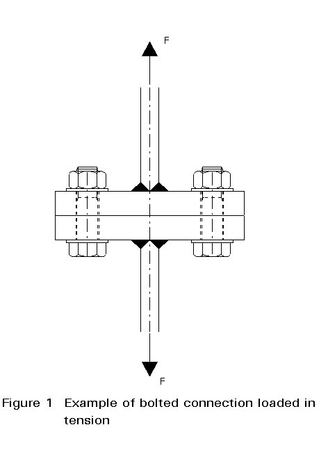
I Bolted connections loaded in tension
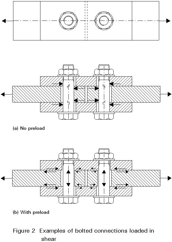
II Bolted connections loaded in shear.
An example of the first type is a bolted flange connection as shown in Figure 1. An example of the second type is a bolted coverplate connection in a flange of a beam section or a simple strip, see Figure 2. In the latter case the load is transferred by shear either in the bolts (for non preloaded bolts) or at the plate surfaces (for preloaded bolts).
In addition to these two load situations, combinations are possible.
Before discussing bolted connections loaded in tension and their specific requirements to prevent fatigue failure, the fatigue behaviour of the bolt (or thread) is discussed.
The thread in a bolt acts as a notch and therefore a high stress concentration is caused at the root of the thread. At two locations of the thread the stress concentration can be even higher, i.e. at the runout of the thread and where the thread of the nut first engages the thread of the bolt.
In addition, the head-shank transition is also a stress concentration.
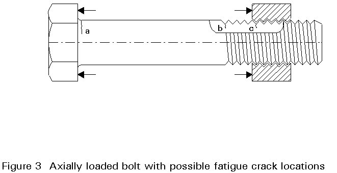
There are, therefore, basically three locations in a bolt with nut axially loaded, where a fatigue crack can initiate in a bolt with nut axially loaded. These locations are:
a. head-shank transition
b. runout of thread
c. thread at nut.
In standard bolts the radius at the bolt-head shank transition is large enough to prevent fatigue cracks at this point.
Normally, if fatigue cracks occur, they will be located at the first engagement of the threads of the bolt and nut (c in Figure 3). This is due to the load transfer from nut to bolt.
The load transfer at the contacting thread faces of the bolt and nut give rise to extra bending stresses in the threads, as shown in Figure 4.
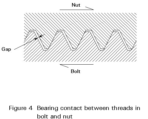
Moreover the load is not equally distributed between the contacting faces of the thread of the bolt and the nut. In most situations the load transfer is concentrated at the first engagement of the thread faces and can be 2 to 4 times the mean value [1]. However this depends on the thread form, pitch difference, difference in Young's modulus where different materials are used etc. The load transfer distribution can become more uniform, by plastic deformation of the nut.
The fatigue behaviour of the thread of a bolt is more or less comparable to the fatigue behaviour of a weld. In both cases there is a notch where a fatigue crack initiates. For the weld it is the weld toe and for the bolt it is the thread root.
Due to the presence of the notch and the resulting high stress concentration factor, the fatigue behaviour is in most cases hardly affected by:
The negligible influence of the mean stress level is caused by the high stress concentration. At the first occurrence of the maximum load level of a cycle, yielding at the notch occurs. The following cycles then cause a stress variation at the notch which has a maximum equal to the yield strength independent of the mean stress level of the load itself. An exception to this is the situation where the bolt thread is made by rolling after the heat treatment of the bolts which results in residual compressive stresses at the thread roots. In that case the fatigue performance is better at low mean load level.
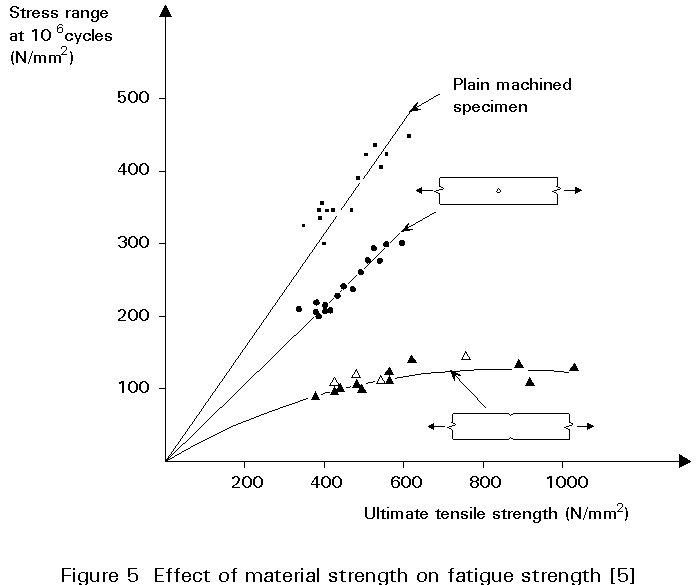
The phenomenon that the material has a negligible effect is explained by the fact that as material strength improves the sensitivity to notches increases. This effect is illustrated in Figure 5 [5] where the influence of the ultimate tensile strength on the fatigue strength for different notch cases is given [5].
Although the notch at a weld (with its undercuts and slag inclusions) is possibly more severe than the machined or rolled notch at the thread root, the concentrated load transfer between bolt thread and nut on top of the inherent stress concentration can cause a relatively poor fatigue performance.
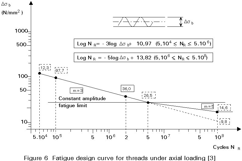
Therefore, in the Eurocode 3 classification [4], axially loaded threads and bolts fall in the category equal to the lowest category for weld details, being class 36. The relevant design line for this category is given in Figure 6. The stress range given on the vertical axis should be based on tensile stress area of the bolt.
It is only mentioned here that according to Clause 9.7.3 of Eurocode 3 a modified design curve may be used for threads and bolts.
As can be seen from the design curve in Figure 6, the constant amplitude fatigue limit for the bolts is 26MPa. This means that, for a constant amplitude loading, there is no fatigue damage where the stress range is less than 26MPa. For a variable amplitude the fatigue limit is 15MPa.
The following example illustrates that the fatigue load bearing resistance is very low compared to the static strength of a bolt. For a bolt under static loading the tension resistance Ft.Rd according to Clause 6.5.5 of Eurocode 3 is given by:
Ft.Rd = 0,9fub As /gMb
Substituting the appropriate values for a bolt M24 grade 10.9 gives the following result:
Ft.Rb = ![]() = 254 kN
= 254 kN
For a constant amplitude fatigue loading at zero mean level containing more than 107 cycles, the allowable maximum force on the bolt will be:
Fmax = DF/2 = DsDAs /2 = 0,5 x 26 x 353 = 4,6 kN
In other words, a bolt designed to transfer a tension force of 254kN may not be fatigue loaded with a maximum force higher than 4,6kN (under the circumstance of zero mean level and more than 107 cycles). This example illustrates the relatively weak fatigue performance of an axially loaded bolt.
Although the fatigue performance of the axially loaded bolt itself is poor, that is not necessarily the case for axially loaded connections. For these connections, the fatigue performance depends on the structural detailing and the applied preload in the bolt.
The effect of preloading, where there is a tensile loading on a bolted connection is illustrated for a flange connection, in Figures 7 and 8. For example, the connection can be a flange connection in a tubular section (chimney or tower). The distribution of the forces is compared for the situation with and without preloading of the bolts. The thickness of the flange is assumed to be large enough to neglect bending flexibility and possible prying forces.
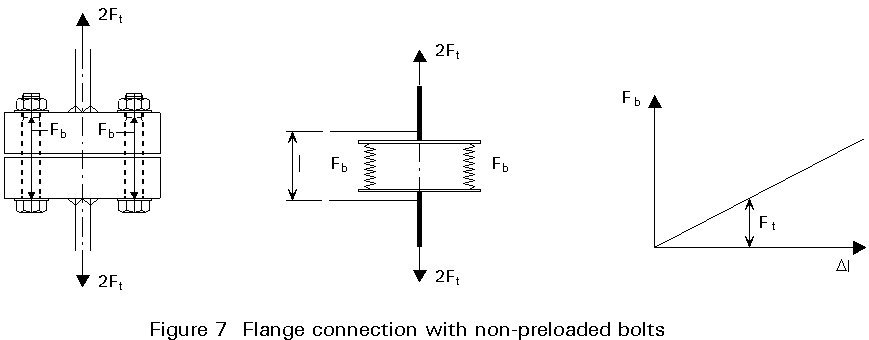
Without Preload
Where there is no preload (Figure 7) and thus no contact force Fc on the facing surfaces of the flanges, the external tensile force Ft applied on the connection will be transferred by the force in the bolts Fb. Therefore the variation of the tensile force Ft will result in a variation of the force in the bolts and at the same time a displacement of the flanges. The connection can be considered as a two spring system as indicated.
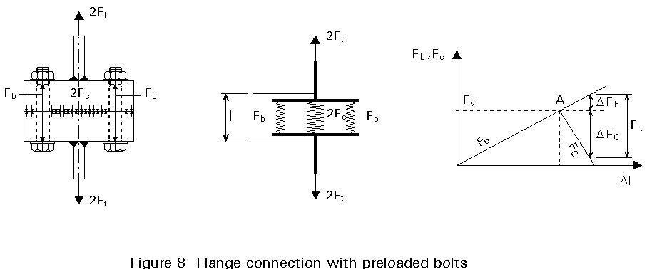
With Preload
In case of preload with a force Fv, this force will initially be in equilibrium with a contact force Fc on the contact area of the flanges, Figure 8. The two flanges now act as one piece as long as the external load Ft is less than the preload Fv.
As a result, when the external load is applied the forces in the bolts will change little. Only the elastic deformation (mainly change in thickness) of the two flanges will cause a change in bolt load. The flanges however are relatively stiff due to their much larger area compared with the bolt area.
However, the load in the bolts will increase rapidly as soon as the contact surfaces separate due to the external force surpassing the preload force Fv. At that moment the situation is equivalent to the non preload case.
As long as the external load Ft is below the preload force Fv the situation can be considered as a three spring system. Two small springs being the bolts and one stiff spring being the two flanges, Figure 8.
The diagram at the right-hand side of Figure 8 gives the relation between the different forces. At no external load (Ft = 0) the elongation due to the preload of the bolts is at point A in this diagram. When an external load Ft is applied, the connection will stretch, resulting in an elongation of the bolts and flange thickness thus resulting in an increased Fb and at the same time a reduction of the compressive force Fc in the flanges as indicated. At each stage the following relation yields:
Fb = Fc + Ft
It follows from the diagram that the increase in the external force is compensated for the larger part by a decrease of the contact force Fc and a small increase in the forces in the bolts Fb.
The amount of variation of forces in the bolts due to the variation in the external forces is dependent on the stiffness ratio of the flanges and the bolts. Therefore, the more flexible the bolts the less force variation they will undergo. Increasing the length of the bolts by inserting washers or using spring washers will be beneficial because it means that the two springs in the diagram (being the bolts and possible washer etc.) are more flexible. Inserting gaskets between the flanges will make the flange assembly more flexible and would have a detrimental effect. The flanges must be thick to reduce the bending flexibility, otherwise the location of the contact area becomes critical.
In the previous section it was shown that preloading the bolts in a tensile loaded connection reduces the force variation in the bolts and therefore can avoid fatigue failure of the bolts. The preload in the bolts must be greater than the external load.
However, preload alone is not always a guarantee for a reduced force variation in the bolts. The contact force of the connection, which is developed by tightening of the bolts to its preload, must also be located in a favourable position as well.
This is illustrated in Figure 9 by a flange connection, where the thickness of the flange is much smaller than in the previous example and is therefore flexible in bending. In the flange connection of two T-sections the location of the contact forces has been established by introducing loose shims in two different ways. The location of the shims defines the location of the contact forces. In both cases the bolts are tightened to the same preload.
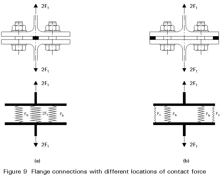
The schematic models of the relevant spring system are also shown in Figure 9.
Contact Area at the Centre
Where the shims and thus the contact force are in the centre, Figure 9a, there is effectively a very stiff spring in the middle compared to the two flexible springs representing the flexibility of the bolt and the bending flexibility of the flanges (the latter in this case being the most important part of the total flexibility). This case is similar to the situation in the previous section with a much larger difference in the stiffness between the contact area and bolts + flanges due to the bending of the flanges.
Contact Area at the End of Flanges
Where the contact area is at the end of the flanges, Figure 9b, the springs representing the contact area and the bending flexibility of the total flanges, are very flexible. Therefore the springs, representing the bolts plus a part of the flanges, have a relatively much higher stiffness. As a result the variation of the external force Ft will result in a variation in the bolt forces of nearly equal magnitude.
Results of Measurements
For the examples above actual measurements of the bolt forces have been carried out [2]. The measured bolt forces in these two situations are given in Figure 10. In each case the bolts were tightened to a preload Fv of 100kN each. In Figure 10 the force in the bolt Fb is plotted by the thick line as a function of the external load Ft. At an Ft of zero, Fb starts at the preload of 100kN. The external force Ft is also given by the dashed line under an angle of 45° . From the equilibrium of the forces it follows that the vertical distance between this line and the thick line of the measured bolt force is equal to the contact force Fc.
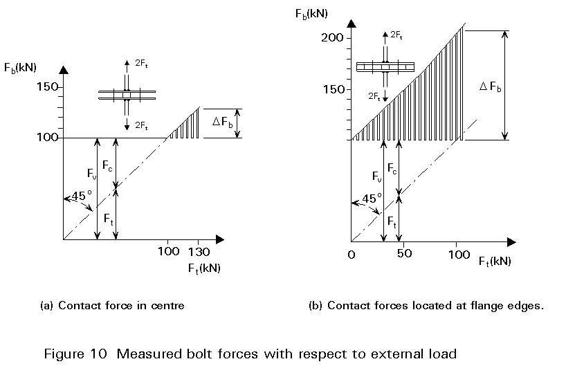
In the situation with the contact in the centre, Figure 10a, the forces in the bolts are almost constant until the external force surpasses the preload Fv. This means that the part of the connection including the contact area (the middle spring in the spring model) is extremely stiff compared to the flexibility of the bolts plus bending of the flanges (side springs in the spring model). As a result the variation in the forces in the bolt is negligible as long as the preload is greater than the external load. Fatigue failure in this case is not to be expected.
This is in contrast to the situation with the contact forces at the end of the flanges, Figure 10b. In this situation the stiffness of the flanges is negligible compared to the stiffness of the bolts. All external load is now transferred by the bolts. Where the external load is a cyclic loading the load variation must be very small, otherwise fatigue failure of the bolts occurs very soon.
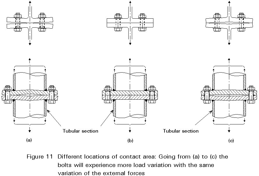
In general the most favourable situation with respect to fatigue resistance is obtained when the contact area is as close as possible to the components in which the tensile force is acting.
In Figure 11 some examples of favourable and less favourable situations are given. More examples are given in [2] and [3].
A simplified example of a bolted connection loaded in shear is shown in Figure 2. The load is transferred from one strip to the other by the coverplates. The connection can be assembled by bolts which are not preloaded and by bolts which are preloaded. Both situations have their own way of load transfer and failure mechanism.
Non Preloaded Bolts
In case of non preloaded bolts the forces are transferred by bearing of the plates against the shank of the bolt and consequently shear in the bolt shank as indicated in Figure 2a. This type of joint can not be used where the variable load changes sign since the clearance between the holes and shank allows large displacements to occur repeatedly.
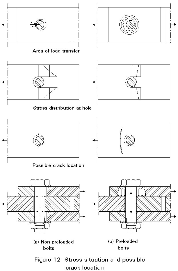
The load transfer in this type of joint is very concentrated at the location where the shank bears against the holes as indicated in Figures 2a and 12a.
Preloaded Bolts
Where the bolts are preloaded, the forces are transferred by friction of the plate surfaces. The bolts which transfer the load by friction are known as High Strength Friction Grip Bolts (HSFG), Figure 12b. High strength bolts and controlled tightening are necessary to obtain sufficient compressive stresses to enable the load to be transferred by friction.
The load transfer by friction takes place over the whole area where compressive stresses are present due to the bolt preloading as indicated in Figures 2b and 12b. Therefore, the load transfer is not as concentrated as with non preloaded bolts. Connections with HSFG bolts can also be used where the variable load changes sign.
Non Preloaded Bolts
For non preloaded bolts there will be a stress concentration at the holes as indicated in Figure 12a.
The stress concentration results from the fact that there is a hole in a stressed plate. Moreover the load is introduced by the bolt shank in a very concentrated way.
Preloaded Bolts
In case of preloaded bolts there is no stress concentration at the holes. The stresses may even be lower than the nominal stress as indicated in Figure 12b.
This is due to the fact that at the hole a part of the load has already been transferred. Moreover the bolt head and nut will reduce the deformation of the hole.
Non Preloaded Bolts
Due to the stress concentration at the hole a fatigue crack can occur there (see Figure 12a). Another possibility is the failure of the bolt as a result of the variable shear load in the shank at the shear plane. The threaded part of the bolt should not be in the shear plane because the notch effect of the thread would reduce the fatigue resistance drastically.
Preloaded Bolts
For preloaded bolts the stresses at the holes are low. Fatigue cracks do not, therefore, occur at the holes. The fatigue crack normally occurs in the gross section of the plates, see Figure 12b.
The contact pressure applied by the preload of the bolt gradually decreases around the hole. The crack initiates where the contact pressure is not high enough to prevent slip between the plate, resulting in crack initiation by fretting.
In this case there are two possible failures - the shank of the bolts and the plates. Both should be verified against the relevant design curves.
For the bolt shank loaded in shear, the design strength according to Eurocode 3 [4] is given in Figure 13. No thread is allowed in the shear plane.
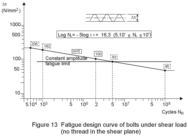
For the plates, the stresses should be calculated for the net section and the detail category 112, according to the Eurocode 3 classification, should be used [4].
In the case of preloaded bolts, the bolts themselves will not fail provided that the preload in the bolts prevents total slip.
The plates fall into the same category as in the non preloaded case. However, since failure does not occur in the net section, the gross section of the plate can be used for calculating the fatigue stresses.
The magnitude of the total preload must be large enough to prevent slip (shear connection) or disappearance of the contact forces (connection loaded in tension) at the maximum possible load on the connection.
Where the connection is loaded in shear, any slip of the connection due to an extreme load can reduce the friction coefficient by an unknown factor. Thus the preload has to be designed on the basis of the maximum extreme load case. The calculation procedure to prevent this is given in ESDEP Lecture 11.3.2. Another way of preventing the slip due to accidental extreme load cases is to use injection bolts [6].
Where the connection is loaded in tension, an "overload" cancelling the contact forces will result in a force variation in the bolt. This in itself will not cause fatigue failure since the number of cycles is limited. However, after this loading, the preload in the bolt can be reduced due to local yielding and resulting plastic deformation of the bolt or contact areas between bolts and flanges.
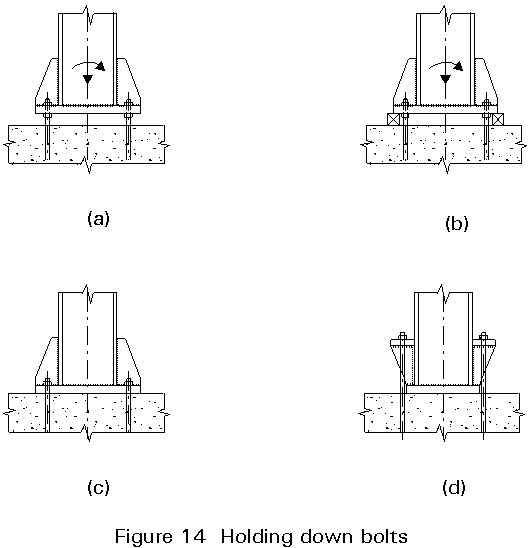
The dimensioning of holding down bolts under static loading and their anchorage into the foundation are described in Lecture 11.3.2.
Concerning fatigue strength, anchor bolts do not behave in the same way as normal bolts; some parameters are different: the thread size, the diameter and the method of forming the thread.
Test results have shown [7] that the bolt diameter and the thread size do not influence fatigue behaviour; the fatigue lives were almost identical for tested specimens as for normal bolts.
On the other hand, the method of forming the thread influences the fatigue strength. Tests were carried out on anchor bolts with rolled threads or with cut threads. The specimens with rolled threads provided the longer fatigue life. This better performance may be due to the compressive residual stresses at the thread root generated by the thread-rolling operation.
When the threads are cut automatically, this operation leaves a transition at their termination. It is a sharp notch adjacent to a region of smooth bar. It has been shown that there is an important stress concentration at the notch which induces fatigue cracks.
Consequently rolled threads appear to improve the fatigue performance of the bolt and are recommended for use when available. Note that the fatigue life of a bolt is a function not only of the bolt thread, but also of the nut.
As already mentioned for common bolts, the use of a double nut increases fatigue resistance and its influence seems to be larger for anchor bolts.
All considerations described in Section 5 concerning the influence of the prying effect are applicable for connections made with holding down bolts. For instance, tests on site have shown that the designs in Figures 14b and d give better fatigue behaviour than the solutions in Figures 14a and c.
× The variable load may change sign.
× The thread of the bolt is allowed in the shear plane.
× The fatigue strength of the connection is enhanced, since the stresses are based on the gross section instead of the net section.
[1] Frost, N.E., March, K.J., Pook, L.P., Metal fatigue, Oxford
University Press 1974, ISBN 0198561148
[2] Bouwman, L.P., Bolted connections dynamically loaded in tension, ASCE, J. of the Structural Division, Vol. 108, No. ST, September 1982.
[3] European recommendations for bolted connections in structural steelwork, No. 38, March 1985.
[4] Eurocode 3: "Design of steel structures": ENV 1993-1-1: Part 1.1, General rules and rules for buildings, CEN, 1992.
[5] Gurney, T.R., Fatigue of welded structures, Cambridge 1968.
[6] Bouwman, L.P., Gresnigt, A.M., Dubois, G.A., European Recommendations for Bolted Connections with Injection Bolts, ECCS-TC10 draft.
[7] Frank, K.H., Fatigue Strength of Anchor Bolts, ASCE, Journal of the Structural Division, vol. 106, ST 6, June 1980.