ESDEP WG 11
CONNECTION DESIGN: STATIC LOADING
Introduction to the design of connections using preloaded bolts in shear and/or tension.
Lecture 1B.1: Process of Design
Lecture 2.4: Steel Grades and Qualities
Lectures 3.2: Erection
Lecture 11.1.1: Connections in Buildings
Lectures 11.3: Other lectures on Bolted Connections
Lectures 11.4: Analysis of Connections
Lecture 12.6: Fatigue Behaviour of Bolted Connections
The basic principles of connection design using high-strength preloaded bolts (HSFG bolts) are established. The load transmission is described for both shear connections and tension connections. The influence of the preload and the tightening of the bolts are considered.
NOTATION
As Stress area [mm2]
Nominal diameter of the bolt (shank) [mm]
do Diameter of a hole [mm]
Fv Shear force [N]
Ft Tensile force [N]
Fp Preloading force of a bolt [N]
Fs Slip resistance of a preloaded bolt [N]
Ma Applied torque [Nmm]
k Coefficient of friction between mating surfaces [-]
Q
Rotation [degrees]m
Slip factor [-]n Number of friction faces [-]
g
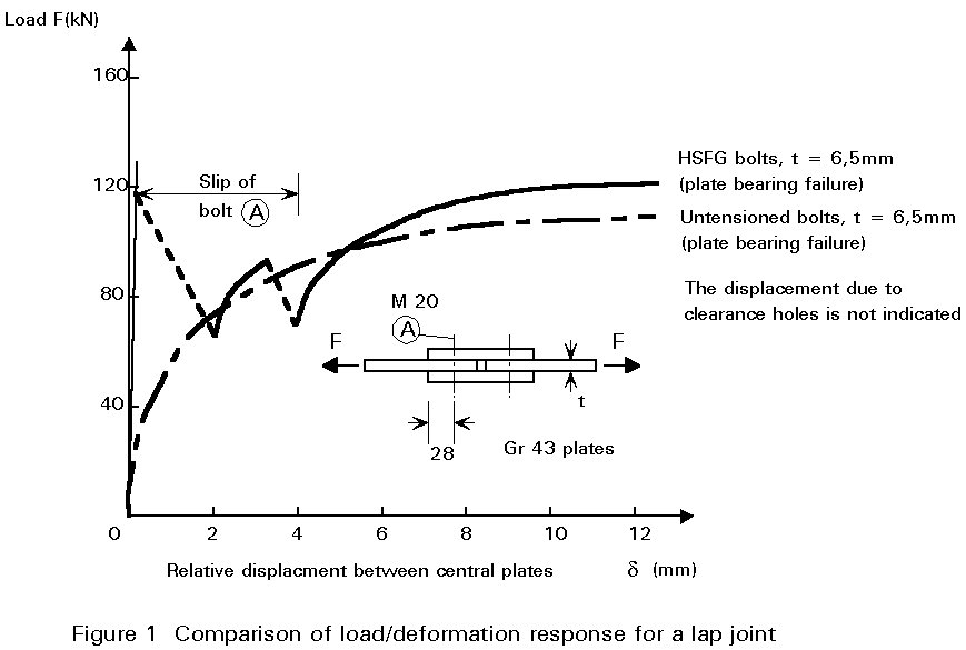
ms Partial safety factors for a slip resistant bolt [-]When a connection is subject to a load reversal or to dynamic loading, a shear connection which acts by shear stress in the bolt and bearing stress in the plates, is not acceptable (Lecture 11.3.1). By pretensioning of the bolts, however, a clamping pressure occurs between the connected parts which enables load to be transferred by frictional resistance. Figure 1 compares the effect of using bearing and preloaded bolts to make-up a double-cover plate butt joint. Until slip occurs the connection which uses preloaded bolts - usually termed High Strength Friction Grip (HSFG) bolts - is seen to be much stiffer than that which employs bearing bolts. Once slip occurs the HSFG connection progressively becomes a bearing one and, after the hole clearance has been taken up, both types of connection behave in a similar way.
In the case of bolts in axial tension, preloading improves the fatigue resistance by reducing the effective stress range.
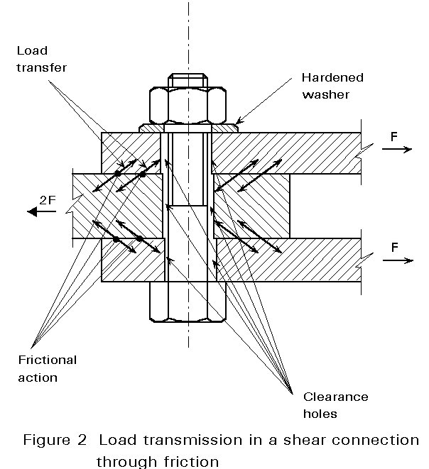
Preloaded bolts exert a compressive stress on the connected plates. The compression gives rise to high frictional resistance, which enables load to be transferred between the connected parts. When the applied load F in Figure 2 exceeds the frictional resistance which is developed between the plates, the plates will slip relative to each other allowing the bolt to act in bearing.
Bolts which transfer load by friction are known as High Strength Friction Grip (HSFG) bolts. Controlled tightening of the bolts allows the frictional action to be quantified for design.
The main advantages of HSFG bolted connections are their greater stiffness and their ability to withstand alternating forces. Their behaviour under fatigue loading is also better than that of bearing bolted connections.
Against these advantages are the costs of HSFG bolted connections. The preparation of the friction grip surfaces and the controlled tightening require additional care (training of people). The costs are greater than for bearing connections. As a result, HSFG bolted connections are usually used only where the stiffness of the connection is important, where alternating loading would cause alternating slip, or where fatigue loading is present.
Typically HSFG bolts are used in bridges, cranes and crane girders.
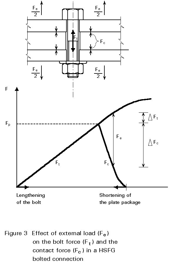
Figure 3 gives the relation between the elongation of the bolt and the shortening of the plate assembly due to preloading. When an external tension force Fe is applied to the connection, the force in the bolt Ft will increase. At the same time the elongation of the bolt increases, and the shortening of the plate assembly decreases by the same amount. As a result, the force in the plate assembly decreases. In practice, the stiffness of the plate assembly is about 4 times the stiffness of the bolt.
The relation between the various forces can be illustrated by the "force triangle" in Figure 4. In Figure 4(a) contact is limited to the central region of the bolted connection. There is no increase in bolt force until separation occurs. In Figure 4(b), contact is limited to the edges of the bolted connection. Any external tension will increase the bending in the plate increasing both Fc and DFb. Further explanation is provided in Chapter 17 of Reference 1 and in Reference 2.
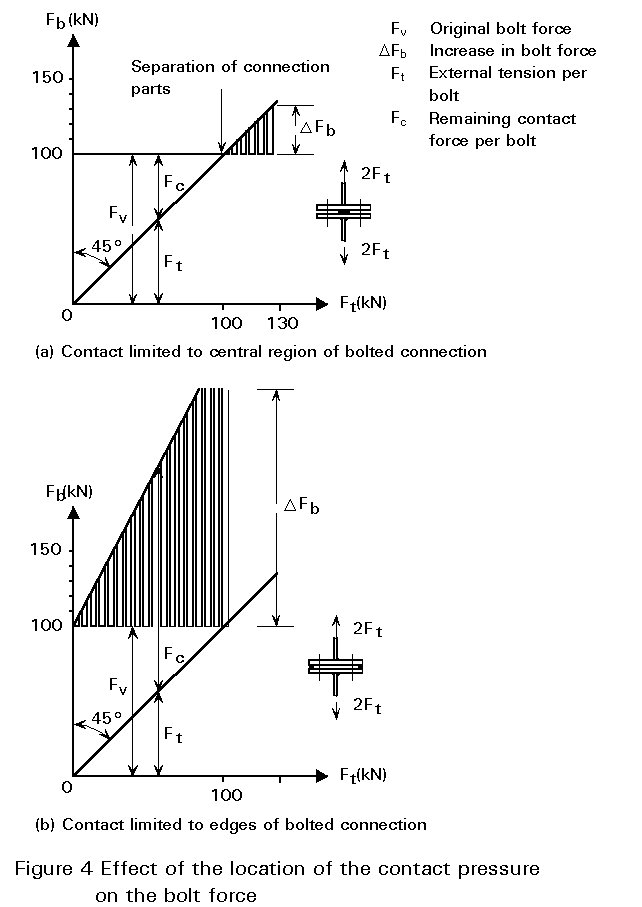
The percentage of the force which is transmitted by an increase in the force in the bolts and the other part which reduces the clamping forces between the plates depends on the elastic behaviour of the connection (see Figure 3). Since the elastic behaviour is the same, the location of the contact pressure produced by tightening of the bolts is of crucial importance with regard to bolt fatigue (see Figure 4).
In order to make practical use of the friction effect, high tensile steel bolts (usually grade 10.9) are used so that an adequate clamping force can be obtained with reasonably sized bolts. The stress induced in the bolts by the pretensioning is at, or near, the proof stress.
The design preloading force of a bolt is given by:
Fp.Cd = 0,7 fub . As
where As is the tensile stress area of the bolt (see Lecture 11.3.1) and fub the nominal ultimate stress of the bolt.
Three methods of tightening are available:
a. Torque method
For this method of tightening a calibrated torque wrench is required which may be hand operated or, for bolts of larger diameters, power operated.
The torque applied to the nut (or the head) is used partly to overcome friction between the nut and the surface against which it rotates, and partly - approximately half - to drive the threads up the helix, overcoming the friction between the mating screw surfaces and the resolved component of the axial force.
If the geometry of the screw head and the coefficient of friction between the various mating surfaces were known, it would be possible to estimate the tension induced by a given torque. The uncertainties concerning distribution of contact pressures, and the variabilities of coefficients of friction in practice, do not justify the use of anything other than a simple rule such as:
Ma = k d Fp (1)
where:
Ma is the applied torque (Nmm)
d is the bolt diameter (mm)
Fp is the preload in the bolt (N)
k is the coefficient of friction between mating surfaces
In practice k values have been measured for new bolts which vary between 0,12 and 0,20. For the as - delivered condition, slightly oiled the ECCS recommendations [3] give k = 0,18 and, for case of the use of the thread lubricant molybdenum sulphide k = 0,14.
It may be concluded from the above that the scatter in the preloads obtained will be large (Figure 5). If the coefficient k appears to be very low, there is a danger that the bolt will break. If k is unexpectedly large, then the desired preload will not be obtained.
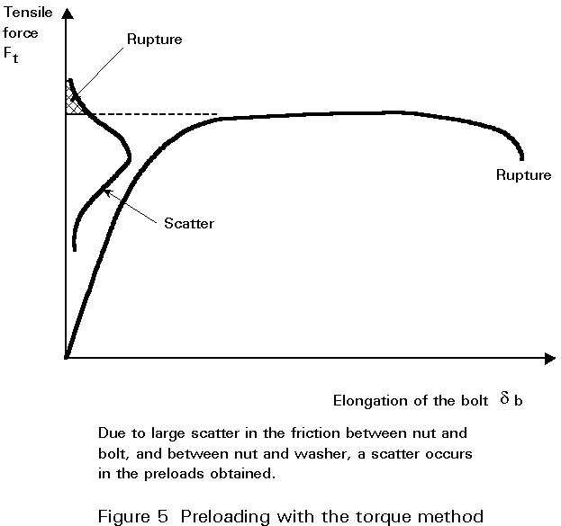
Therefore, the torque method is not recommended by the ECCS [3] and Eurocode 3 [4]. If it is applied, then it is recommended that tests are carried out before erection. Special devices are available ("bolt force metre") to measure the bolt force as a function of the torque Ma.
b. Turn-of-nut method
This method is based on a predetermined rotation of the nut. The tightening can be achieved in two ways as follows:
Q = 90° + S t + d (2)
where:
Q is the rotation in degrees
S t is the total thickness of connected parts in mm
d is the bolt diameter in mm.
The purpose of this method is to rotate the nut sufficiently to take the bolt well into the plastic state (Figure 6a). The shank tension is then comparatively insensitive to variation in the nut rotation, while a large reserve exists before rupture occurs.
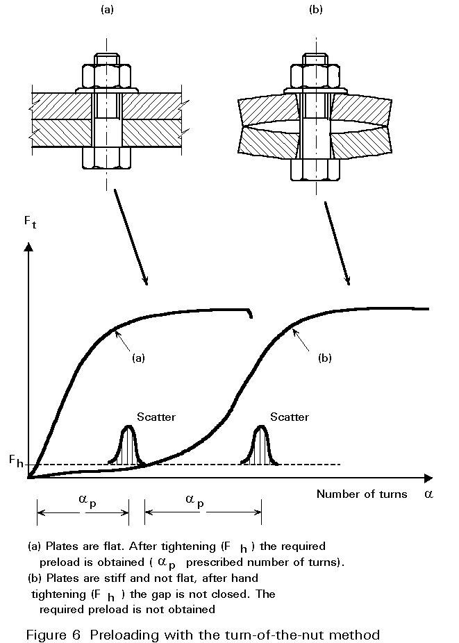
It should be remembered that the ductility of the bolt largely depends on the length of the threaded portion. Care must be taken with short bolts which have only a small amount of thread in the grip (5 threads is a minimum).
The danger of overloading (breaking) the bolt in the turn-of-nut method is far less than in the torque method.
Where the plates are not flat and parallel as indicated in Figure 6b, this method has the disadvantage that the preload will not be reached if the construction worker does not pay enough attention to closing the gaps. A requirement of the method is that the contact surfaces must fit snugly before the bolts are tightened up.
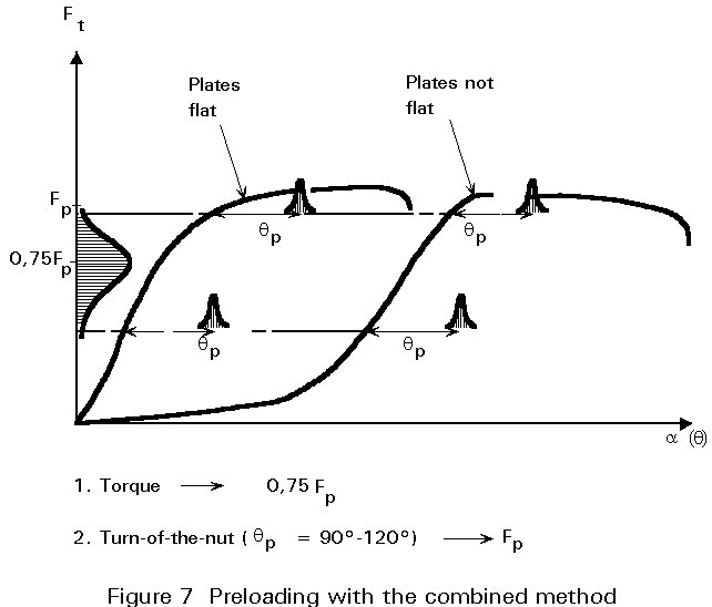
c. Combined method (the best)
In this method the torque method and the turn-of-nut method are combined.
1. First tighten all bolts to 75% of the full preload, using the torque method. By applying only 75%, the danger of overloading due to an unexpected low friction between nut and thread is acceptably small. At the same time the clamping force is usually large enough to close any gaps between the plates.
2. Then tighten by a further turn of 90° to 120° (the lower value for small bolt lengths and the larger value for large bolt lengths).
This method has the advantage that it is not particularly sensitive to:
The above is illustrated in Figure 7:
In connections with several bolts (Figure 8), it is necessary to tighten the bolts in two stages:
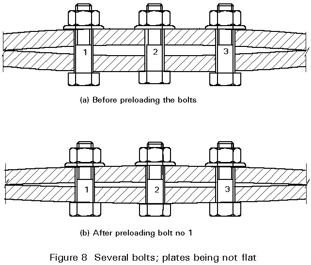
The reason for the above is that after tightening the first bolt up to 75% of Fp or even Fp, the contact surfaces may not fit snugly. The fit depends on the imperfections of the joint (the plates not being flat) and the stiffness of the plates, compared to the preload of the first tightened bolt.
If the contact surfaces do not fit snug after the first bolt is tightened, tightening the second bolt will decrease the preload in the first bolt, and so on.
By applying the two stage procedure, this effect is reduced to an acceptable level.
Failure of threaded fasteners due to over-tightening can occur by bolt shank fracture or by stripping of the threads of the nut and/or bolt. Shank fracture is sudden and therefore easily noticed. Stripping is gradual and therefore difficult to detect. It introduces the danger of partly failed fasteners being left in assemblies. Figure 9 gives the results of tension tests with both failure modes.
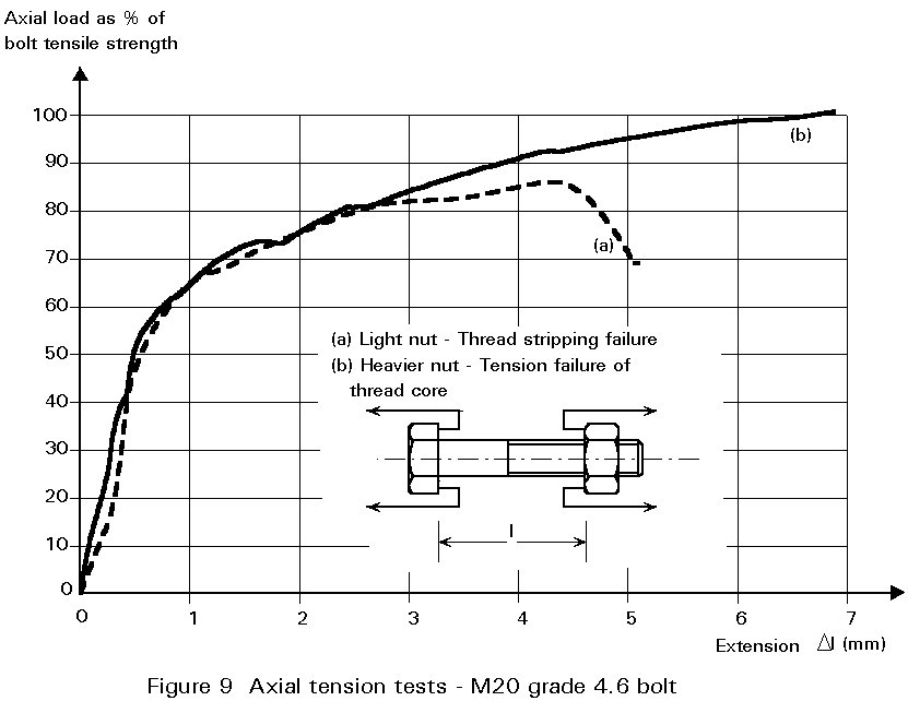
It would be desirable therefore to design threaded connections so that their mode of failure would always be by shank fracture. Unfortunately, because of the many variables which govern stripping strength (nut and bolt material strengths, thread clearances, across-flats dimensions, etc.), nuts would have to be abnormally thick to guarantee this mode in all cases.
Nuts with a width across flats according to ISO 898/2 [5] are used for preloaded bolts. Their nominal height is always greater than the classical value 0.5 d; it is often equal to 0,8 d and it can reach 1,0 d.
In this respect an important quality requirement arises. The bolt with its nut in a tensile test as indicated in Figure 9 must have a rupture strength of at least the so-called "proof stress". The proof stress for ISO 898/1 [6] bolts, for instance, differs somewhat from the design values for fub.
A hardened steel washer is placed under the part that is rotated (the nut or the head). This leads to a more uniform and not too high friction between the rotated part and the underlying plates. When the bolt axis is not normal to the contact surface (difference of more than 3°), an appropriate taper washer must be used.
Clearance values are the same as for non-preloaded bolts (see Lecture 11.3.1.).
In normal circumstances, the clearance is 2mm for diameters up to and including 24mm and 3mm for larger diameters.
To improve the resistance of the connection, holes with smaller clearance than standard holes may be specified. As a result costs will be greater.
HSFG bolts in shear connections transmit the force by friction between the contact faces (Figure 1). The resistance of these connections depends on the preload Fp.Cd, the slip factor m and the number of friction faces n. The design slip resistance of a preloaded high strength bolt has a value:
Fs,Rd = nmFp.Cd /gms (3)
The slip factor m depends on the preparation of the surfaces. Some values (1) are:
| surface not treated | m = 0,20 |
| surface blasted with shot or grit, with any loose rust removed, no pitting | m = 0,50 |
| surface blasted with shot or grit and painted with ethyl-zinc silicate coat (thickness 30 - 60 m m) | m = 0,30 |
| surface blasted with shot or grit and hot dip galvanised | m = 0,10 |
Painting may be necessary to prevent rust in the period before or during erection. Reference standard 8 of Eurocode 3 [4] gives more details.
Figure 2 compares the effect of using bearing and HSFG bolts to make up a double cover plate butt joint. Until slip occurs, the connection which uses HSFG bolts is seen to be much stiffer than that which uses bearing bolts. Once slip occurs, the HSFG connection progressively becomes a bearing connection and, after the hole clearance has been taken up, both connections behave in a similar way. The reason for the large decrease of the force transmitted by friction can be explained by:
|
for the ultimate limit state |
gms = 1,25 |
× for the serviceability limit state |
gms = 1,10 |
If a slip resistant connection is subjected to an applied tensile force Ft in addition to the shear force FV tending to produce slip, the slip resistance per bolt is taken as follows:
Fs,Rd = nm(Fp.Cd - 0,8Ft) /gms
If, in a moment connection, the applied tensile force is counter balanced by a contact force on the compression side, no reduction of the slip resistance is required.
Tests carried in several countries have shown that mill scale adhering to the contact surfaces causes a substantial reduction in the coefficient of friction. Measures must therefore be taken to remove it.
Depending on the slip factor m assumed, the contact surfaces shall be cleaned and roughened by blasting or shot peening with an appropriate material (sand, steel grit, etc.).
The material used for blasting should be carefully selected (sand, steel shot, cast iron shot, wire shot, etc.) and the treatment should be carried out, making full use of all that is known of the process, so as to achieve a favourable slip factor. This treatment shall be followed immediately by the application of an appropriate paint, if it is specified.
When flame-cleaning is used, it is particularly important that full use should be made of experience gained with regard to burner action (possible use of two burners), the gas-oxygen mixture and the angle of inclination of the flame to the surface of the plate.
Parts to be joined with preloaded high strength bolts must be protected against corrosion by suitable measures designed to prevent moisture penetrating to the contact surfaces and the bolt holes. Such a protection (e.g. sealing) may also be necessary as a temporary measure when joint faces are left wholly or partially exposed during erection. All necessary precautions shall be taken, during fabrication and erection, to ensure that the slip factors assumed for the calculation are achieved and maintained.
When the joint is assembled the contact surfaces must be free from dust, oil, paint, etc. Spots of oil cannot be removed by flame-cleaning without leaving harmful residues and must be removed by suitable chemical means. If the parts cannot be assembled as soon as the contact surfaces have been treated, it is sufficient to remove any thin films of rust or other loose material by brushing with a soft steel brush. During this process the prepared surface must not be damaged, oiled or greased.
If structural components in which the contact surfaces have been prepared for friction grip bolting are stored for very long periods, there is a risk of rusting. Under certain circumstances a lower slip factor must be considered. An effective means of protecting the contact surfaces is to apply self-adhesive or sprayed-on films of plastic. Up to the present, however, no protective coating is known which does not affect the slip factor adversely.
[1] Kulak, G. L., Fischer, J. W. and Struik, J. H. A., "Guide to Design Criteria for Bolted and Riveted Joints", 2nd edition, John Wiley and Sons, 1987.
[2] Bouwman, L. P., "Fatigue of Bolted Connections and Bolts Loaded in tension", Delft University of Technology, Department of Civil Engineering, Report. 6-79-9, July 1979.
[3] European Recommendations for Bolted Connections in Structural Steelwork. European Convention for Constructional Steelwork (ECCS), Publication No. 38, 1985.
[4] Eurocode 3: "Design of Steel Structures": Part 1.1: General Rules and Rules for Buildings, CEN, 1992 (see Chapter 6: Connections Subjected to Static Loading, and Chapter 7: Fabrication and Erection).
[5] ISO 898/2, International Standard Mechanical Properties of Fasteners.
Part 2: Nuts with Specified Proof Load Values.
[6] ISO 898/1, International Standard Mechanical Properties of Fasteners.
Part 1: Bolts, Screws and Studs.