ESDEP WG 11
CONNECTION DESIGN: STATIC LOADING
To review the behaviour and the basis for design of local elements in connections.
Lecture 1B.5: Introduction to Design of Industrial Buildings
Lecture 1B.7: Introduction to Design of Multi-Storey Buildings
Lecture 2.3: Engineering Properties of Metals
Lecture 2.4: Steel Grades and Qualities
Lecture 11.1.2: Introduction to Connection Design
Lectures 11.2: Welded Connections
Lectures 11.3: Bolted Connections
Lecture 11.4.1: Analysis of Connections: Basic Determination of Forces
Lecture 11.4.2: Analysis of Connections: Distribution of Forces in Groups of Bolts and Welds
Lecture 11.5: Simple Connections for Buildings
Lecture 11.6: Moment Connections for Continuous Framing
Lecture 11.7: Partial Strength Connections for Semi-Continuous Framing
This group of 4 lectures (11.4.1 - 11.4.4) explains how the behaviour of local elements in connections may be analysed so that each component may safely be proportioned to resist the loads it is required to transfer. It therefore develops the basic concepts of force transfer that were presented in general terms in Lecture 11.1.2.
This third lecture describes the ways in which the transfer of direct tension, compression or shear forces may be arranged within a connection. It therefore deals with the analysis of cover plates, load transfer using gusset plates and the transfer of shear forces in beam to column, beam to beam and beam splice connections.
The notation of Eurocode 3 [1] has been adopted.
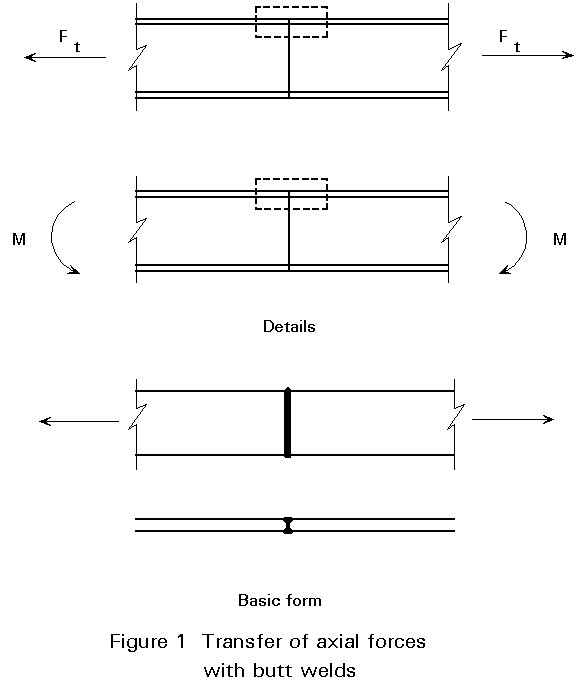
The butt welded connections of Figure 1 require no real calculation, since butt welds are designed to have at least the same strength as the connected plates.
Figure 2 shows some connections in which the tensile force in the flanges or in the webs is transferred by means of cover plates. These cover plates can be present on one side (single) or on both sides (double). They can be connected with bolts or welds.
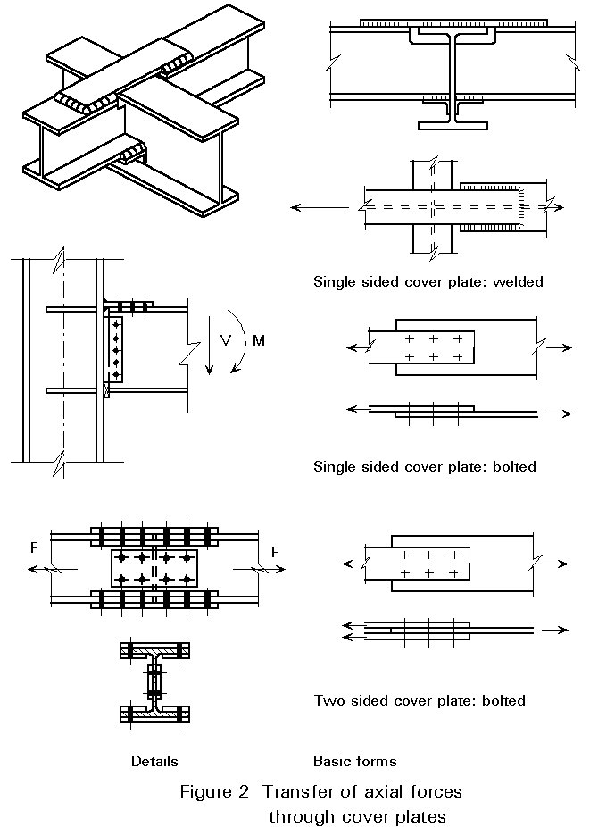
Double sided cover plates have the advantage that eccentricities in the load path and associated eccentric deformations are excluded.
In the welded flange plate in Figure 3, the design strength may be governed by either the plate or by the welds.
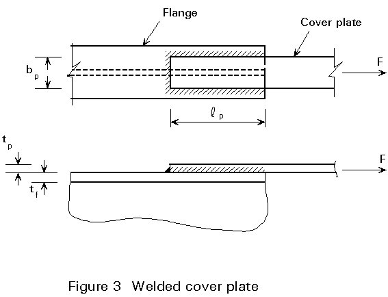
Plate:
F £ bp tp fy (1-1)
Welds:
The design resistances of the end fillet weld and the side fillet welds may be added (see Section 1.2 of Lecture 11.4.2). When the mean stress method (EC3 main test) is applied, it follows:
F £ (2lp + bp) . a . fvw.d (1-2)
where:
lp is the length of the side weld
bp is the length of the end weld
fvw.d = fu/(Ö3bwgMw) (1-3)
For FeE 235: F £ (2lp + bp) . a . 208 (1-4)
If the stress component method according to Annex M of Eurocode 3 [1] is applied, then fvw.d is the same for the side fillet welds, but for the end fillet welds, fvw.d is a factor ![]() greater, see Table 1.
greater, see Table 1.
|
FeE 235 |
FeE 275 |
FeE 355 |
FeE 40 |
|
|
fvw.d.end [N/mm2] |
255 |
286 |
321 |
328 |
|
fvw.d.side [N/mm2] |
208 |
234 |
262 |
268 |
Table 1: Design values for the stress in end fillet welds and in side fillet welds (based on Annex M of EC3)
With the stress component method it follows:
F £ 2 lp a fvw.d.side + bp a fvw.d.end (1-5)
For FeE 235: F £ 2 lp a 208 + bp a 255 [N/mm2] (1-6)
Flange:
The force is transferred from the flange via the welds into the cover plate. The design resistances of these elements must be consistent:
a . fvw.d.side £ tf . 0,58 fy (1-7)
a £ 0,58fytf /fvw.d.side (1-8)
For FeE 235: a £ (0,58 . 235 / 208)tf = 0,65tf (1-9)
This requirement means that design of very short and very thick welds is not allowed, because the adjacent plate material is overloaded.
For the bolted flange in Figure 4, the following checks should be carried out:
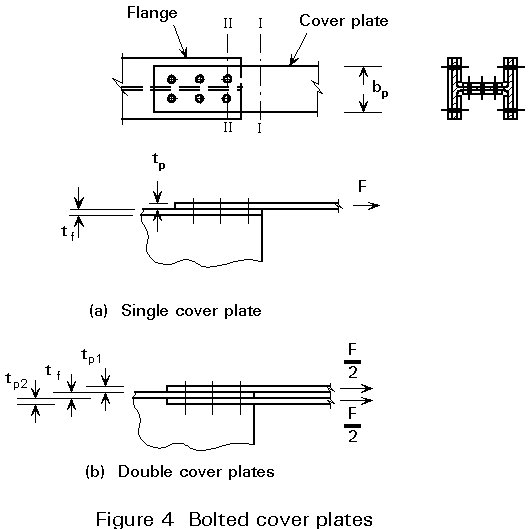
Plate:
Gross section I-I: F £ bp tp fy (1-10)
Net section II-II: F £ ![]() (1-11)
(1-11)
where do = hole diameter
Bolts:
If the length of the connection is less than 15 d, then the force may be assumed as uniformly distributed over all bolts. Thus, for the connection in Figure 3a:
Fs.d = ![]() (1-12)
(1-12)
The bolt force Fs.d must not exceed either the shear resistance Fv.d or the bearing resistance Fc.d according to Chapter 6 of Eurocode 3, see also Lecture 11.3.1.
The bearing resistance of both the flange plate with thickness tp and the flange with thickness tf must be checked.
In the design of double cover plates (Figure 4b) it is usually assumed that each cover plate carries half the force to be transferred. In this case the bolts have two shear planes, which means that the design shear resistance Fv.d per bolt is twice that for the case of a single cover plate. For connections longer than 15d, see Section 1.1 of Lecture 11.4.2.
For the design of a splice in rolled members, the following general rules should be applied:
a. Design the parts of the connection according to the stress situation in the connected members, and make the connections as short as possible.
For the HE section in Figure 4 this rule means that the flanges must be connected and also the web. The connection of the flanges must be designed to transfer the force in the flanges whilst the connection of the web must be designed to transfer the force in the web.
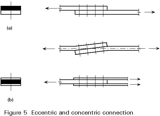
b. Avoid eccentricities as much as possible.
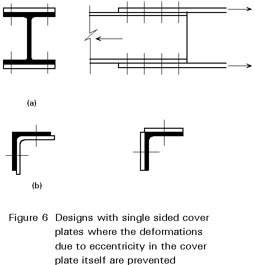
Though the design resistance of the connections a and b in Figure 5 does not differ very much (apart from the shear resistance of the bolts), the deformations differ considerably, especially when the load approaches the design resistance of the connection. Symmetry can prevent unfavourable deformations, see Figure 6a.
In connections with angles, the eccentricity moments usually can be carried by the other leg. Using cover plates on the outside or a somewhat thicker angle section on the inside, assists in avoiding large deformations due to eccentricity, see Figure 6b.
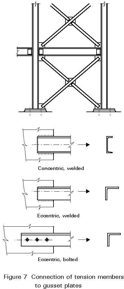
Braces are often connected via gusset plates to the main structure, e.g. the connection of the braces in Figure 7. Gussets are also used in trusses for the connection of braces to the chords.
In the connection of a channel-section to a gusset as shown in Figure 8, all elements in the load path must be checked:
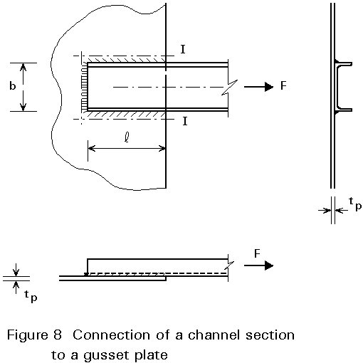
The design resistance of the weld configuration can be checked in the same way as discussed in Section 1.2.
The eccentricity between the force F in the channel-section and the gusset plate has little influence on the resistance, and may normally be disregarded.
For the check of the gusset plate (section I-I in Figure 8) it follows that:
F £ (2 l tp . 0,58 fy + b tp fy) (1-13)
If instead of the yield strength, the ultimate strength is taken for this check (which is consistent with the other design calculations for connections), then as an alternative the following may be applied.
F £ ![]() (1-14)
(1-14)
In the welded connection of an angle to a gusset plate (Figure 9), the forces in both side fillet welds must be in equilibrium with the axial force in the angle section. Because of the eccentric position of the centroid of the angle relative to the welds, the forces F1 and F2 are not equal.
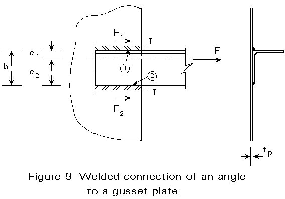
F1 = ![]() and F2 =
and F2 = ![]() (1-15)
(1-15)
Thus, the side fillet weld (1) must be thicker than weld (2). Usually also an end fillet weld is applied. For reasons of deformation capacity, the thickness of such an end fillet weld should be chosen to be equal to the thicker side fillet weld (1), as explained in Section 1.2 of Lecture 11.4.2. Alternatively, the lengths could be adjusted to produce a balanced arrangement. In practice one of the following is usually adopted:
- give weld 2 the same thickness and length as weld 1;
- give weld 2 the same thickness as weld 1, but reduce its length;
- ignore the eccentricity according to 6.6.10 of EC3.
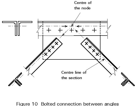
In a bolted connection of angles to a gusset plate (Figure 10), it is not possible to position the bolts on the centre line of the angle because space is required for the bolt head or nut and for access for the tightening equipment.
The eccentricity moment (F(w-e)) in Figure 11 causes extra forces in the bolts. The maximum bolt force is:
R = ![]() (1-1)
(1-1)
where:
H = ![]() and V =
and V = ![]() (1-17)
(1-17)
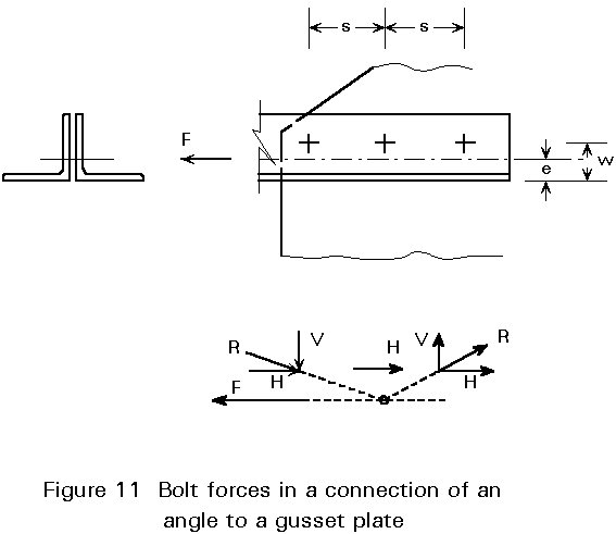
In practice the effect of eccentricity may be approximately accounted for by means of a multiplication factor y on the force H. For usual dimensions of these connections, the following values may be used:
In order to prevent the deformation caused by eccentricities in the action line of the force and the gusset plate (Figure 9), see also Section 1.2, design the member with two angle sections or channel-sections, see Figure 12.
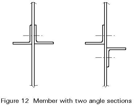
An exception can be made for secondary members, e.g. bracings with only small loads.
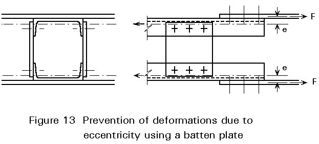
In trussed members with a 'material-free' axis, i.e. the centroidal axis does not coincide with any part of the member, connected with two gusset plates, the deformation caused by eccentricity can be prevented by means of a batten plate, see Figure 13.
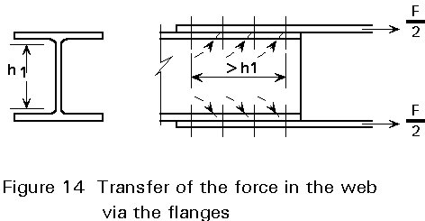
In Lecture 11.3 it is explained that, for the determination of the design resistance in angle sections connected on only one flange, the net section must be reduced to allow for the very uneven stress distribution. A similar problem arises in truss members with an I-section, where only the flanges are connected (Figure 14). This problem can be solved by giving the connection sufficient length to enable the force transfer from the web to those parts of the flange where the force in the flange itself already has been transferred partly to the gusset plate.
In the design of gusset plates the spread of forces acting on the plates must be taken into account. Figure 15 shows the stresses that are caused by a point load on a plate, when the theory of elasticity is applied.
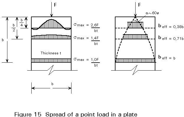
Instead of the uneven stress distribution of Figure 15, the concept of an effective breadth may be adopted, as is illustrated in Figure 16.
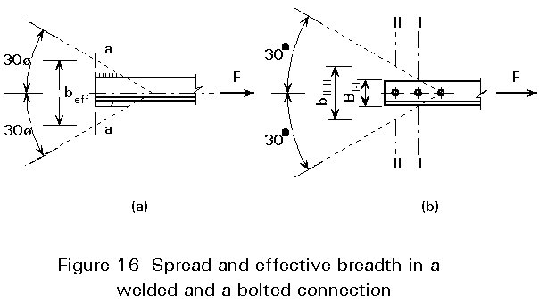
Figure 17 shows a number of connections which are designed to transfer shear force only from a beam into a column. The designs (c) and (d) however, may also be used in moment connections, see for example Figure 3.
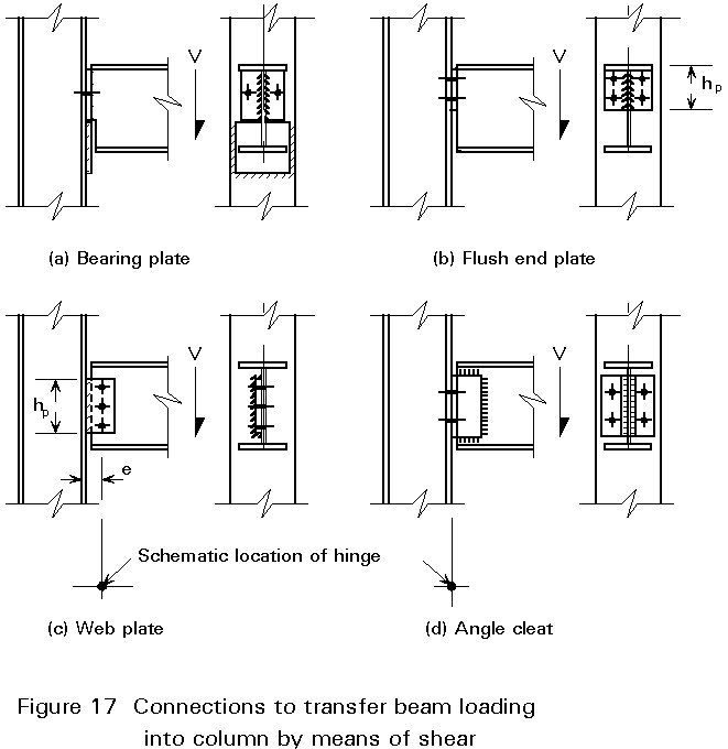
In the design of (a) and (b), it may be assumed that the fasteners (welds and/or bolts) are loaded by shear force only. The design of the fasteners is virtually the same as in the design of the cover plates in Section 1.2.
Apart from the fasteners, the shear strength of the adjacent part of the web of the beam and the shear strength of the end plate must also be checked. For example, for the flush end plate in design (b) the following checks must be carried out.
Gross section: V £ 2 hp tp 0,58 fy (2-1)
Net section: V £ 2(hp - 2dh) tp 0,6 fu/1,25 (2-2)
In the designs (c) and (d), the connection to the column or the connection to the beam must be designed for the eccentricity moment, because the distance between the centroids of the fasteners is too big to be ignored. The choice of the point where the bending moment is assumed to be zero, determines which fasteners must be designed for the eccentricity moment. In Lecture 11.4.1: Section 3.1 it was shown that the stiffness ratio should determine this choice, see also Lecture 11.4.1: Figure 10.
In Figures 17c and 17d, the point where the moment is assumed to be zero (the "hinge"), is indicated.
The design of the weld (Figure 17c) which connects the web plate to the column may readily be conducted using the stresses in the parent material (see Lecture 11.4.2: Section 1.2). The maximum stresses are:
t
xy =The design of the weld configuration in Figure 17d must be based on the load acting on the welded joint as a whole (see Lecture 11.4.2: Section 1.2). This design can be carried out in two ways, methods (a) and (b), see Figure 18.
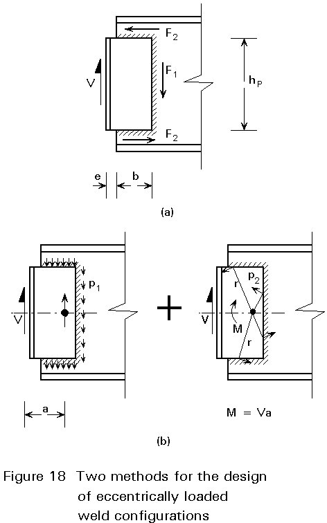
Method (a) is based on the assumption of a simple, equilibrium system of forces. It is assumed that the vertical weld transfers the shear force V through shear. The eccentricity moment is accounted for by shear forces in the horizontal welds:
F1 = V and F2 = ![]() (2-4)
(2-4)
A disadvantage of this method is that the calculated weld thickness may differ considerably for the vertical and horizontal welds.
Method (b) is based on the same principle as the method discussed in Lecture 11.4.1: Section 3.2 for the design of a bolt group with a free centre of rotation, see Lecture 11.4.1: Figure 13.
The shear force V is transferred to the centroid of the weld configuration. This force V is evenly distributed over the welds and gives a small force p1 per unit of weld length, see Figure 18b. The remaining design resistance of the welds
p2 = a fvw.d - p1 (2-5)
must allow for the eccentricity moment. It is assumed that the forces p2 are perpendicular to the line from the centre of rotation (the centroid), and therefore contribute to the moment resistance by r . p2.
This method is more accurate and can be applied for weld groups with constant weld thickness. A disadvantage is that this method is too laborious for manual calculations. In computer calculations this disadvantage is absent.
Another possibility is the use of design charts that are based on this method. Figure 19 shows such a design chart.
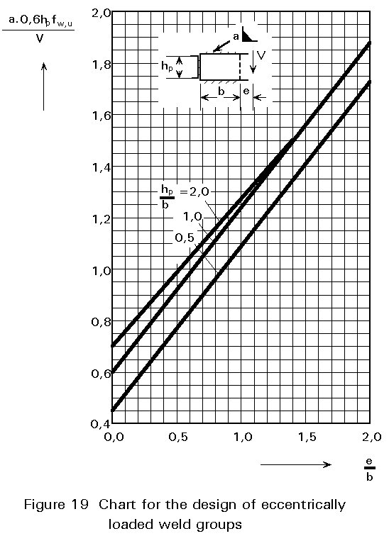
Figure 20 shows several types of beam-to-beam connections. Taking into account the very low torsional rigidity of the main beam (I-section), it may be assumed that the line of action of the shear force is at the web of the main beam.
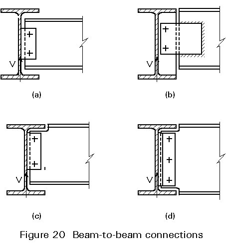
Following this assumption, the design of the various fasteners and checks can be carried out as discussed above.
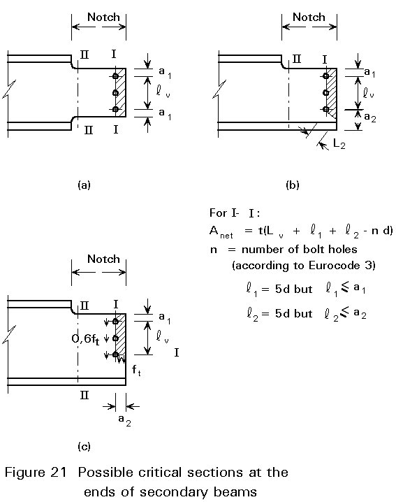
If the top flanges of both beams must be situated at the same level, and it is desired to keep the eccentricity moment as small as possible, then a part of the flange of the secondary beam must be cut away to form a notch.
If the main beam and the secondary beam have the same depth, this work must be carried out on the top flange and on the bottom flange.
The section in the secondary beam where the flange(s) is (are) cut away, are weakened. The weakened section must be checked. Figure 21 shows the two sections that can be critical. The gross section II-II must be checked for the combination of shear forces and bending moment. Further, the net section I-I must be checked for block shear using Anet to Eurocode 3, see Figure 21.
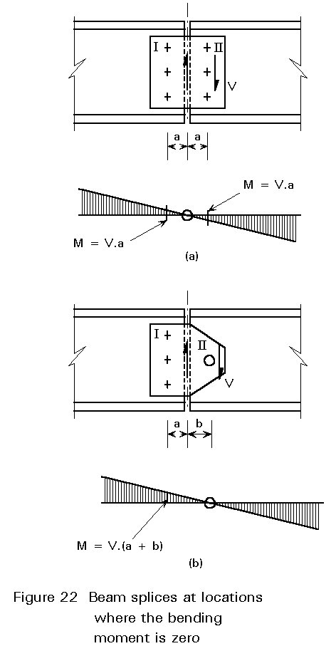
In Section 1 of Lecture 11.4.3, the use of splices to transfer an axial force was discussed. Splices in beams normally transfer shear force and may also be required to transfer a bending moment. However, in many designs the splices are positioned at the point where the bending moment is zero. In such cases, only the beam webs need to be connected, because the shear force is located there, see also Section 2 of Lecture 11.4.1.
Figure 22 shows two possibilities. Design (a) is the more common. Since both bolt groups I and II have the same stiffness, it is logical to select the place where the bending moment is zero as the centre of the splice. Both bolt groups must therefore be designed for the shear force V and the eccentricity moment V . a. For the determination of the bolt forces see Figure 15 of Lecture 11.4.2.
If, in addition to the shear force V, a bending moment Msp must also be transferred, then the flanges may also need to be connected. This connection may, however, not be necessary if the moment is sufficiently small that it can safely be transferred via the web cover plates alone i.e. Msp £ Mweb in Figure 23a.
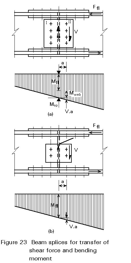
The moment Msp is transferred partly by the flanges and partly the web, in proportions depending on the relative contributions to the stiffness of the whole beam (Itot).
The bolt group II in Figure 23a is the more heavily loaded group in the web and must be designed for the shear force V and a bending moment: Mweb + V . a.
Another possibility is to assume that the whole of the bending moment Msp is transferred by the cover plates on the flanges as illustrated in Figure 23b such that:
Mfl = Msp/(h - tfl) (2-9)
In this case the web plates need only transfer the shear force V (including the eccentricity effect). The loading and design calculations are then the same as for the splice in Figure 22a.
[1] Eurocode 3: "Design of Steel Structures ENV 1993-1-1: Part 1.1, General rules and rules for buildings, CEN, 1992.