ESDEP WG 11
CONNECTION DESIGN: STATIC LOADING
To review the behaviour and the basis for design of local elements in connections.
Lecture 1B.5: Introduction to Design of Industrial Buildings
Lecture 1B.7: Introduction to Design of Multi-Storey Buildings
Lecture 2.3: Engineering Properties of Metals
Lecture 2.4: Steel Grades and Qualities
Lecture 11.1.2: Introduction to Connection Design
Lectures 11.2: Welded Connections
Lectures 11.3: Bolted Connections
Lecture 11.4.1: Analysis of Connections: Basic Determination of Forces
Lecture 11.5: Simple Connections for Buildings
Lecture 11.6: Moment Connections for Continuous Framing
Lecture 11.7: Partial Strength Connections for Semi-Continuous Framing
This group of 4 lectures (11.4.1 - 11.4.4) explains how the behaviour of local elements in connections may be analysed so that each component may safely be proportioned to resist the loads it is required to transfer. It therefore develops the basic concepts of force transfer that were presented in general terms in Lecture 11.1.2.
This second lecture concentrates on the behaviour and design of groups of fasteners (bolts or welds) as used in the types of connection described in Lecture 11.1.2. Methods are presented for assessing the load on each individual fastener (bolt or length of weld) and for determining the total resistance of the group acting in combination. The specific topics covered include: long bolted joints, long welded joints, weld groups, bolt groups and welds and bolts designed to act together in resisting the same applied forces.
The notation of Eurocode 3 [1] has been adopted.
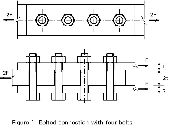
When several bolts are placed in a row, as is indicated in Figure 1, then assuming elastic behaviour, an uneven distribution of forces occurs. This distribution can easily be demonstrated when two extreme situations are considered, see Figure 2.
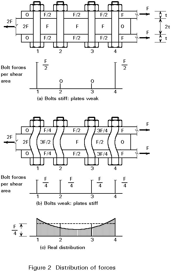
a. Assume the bolts are infinitely stiff and the plates are weak
The bolts do not deform. They remain straight and parallel to each other. Each piece of plate between a pair of bolts therefore has the same length, the same strain and consequently also the same stress. In the example of Figure 2, this means that the forces in the plates between bolt 1 and bolt 2 are: 0,5 F, 1,0 F and 0,5 F. But this also applies to the plates between bolts 2 and 3 and between bolts 3 and 4.
Conclusion: the bolts 1 and 4 transmit the full load F. The other bolts are not loaded, see Figure 2a.
b. Assume the plates are infinitely stiff and the bolts are weak
The plates between the bolts do not deform. In other words, every bolt has the same deformation and therefore is loaded to the same extent. Every bolt carries 0,5 F, i.e. 0,25 F per shear area.
The real distribution of forces is between these two extremes, as is indicated by the solid line ("elastic") in Figure 2c.
The difference between the forces in the outer bolts and the inner bolts is greater when the stiffness of the plates is low. This situation occurs when the connection is longer (more bolts) and the plate thickness compared to the bolt diameter is small.
For practical ratios of plate thickness to bolt diameter and practical values for the pitch, the following approximate distributions (%) of bolt forces apply:
- with four bolts 29-21-21-29
- with six bolts 25-15-10-10-15-25
- with eight bolts 24-13-8-5-5-8-13-24
Design recommendation
The part of the connection between the outer bolts must be designed to be as short and stiff as possible, in order to minimise the differences between the bolt forces.
In practice, however, it is normally permissible to assume an even distribution of forces, owing to the plastic deformation capacity of the bolts and plates. When a bolt is overloaded, or a plate in bearing is overloaded, it will deform plastically. Then, through redistribution of forces, a more even distribution of the forces in the bolts is obtained.
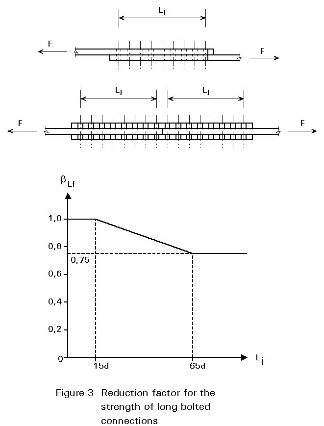
The amount of deformation capacity that is needed, is greatly influenced by the length of the connection:
bLf = 1 - (Lj - 15d)/200d (1-1)
but bLf £ 1,0 and bLf ³ 0,75.
The deformation capacity is provided by the bolt (bending and shear) and/or by the plates (yield of net area, ovalization of the bolt hole caused by bearing stresses).
Another cause of uneven distribution of forces and thus of a need for deformation capacity is the possibility of misalignment of bolt holes. Because of fabrication tolerances the diameter of the holes is chosen as the diameter of bolt plus a clearance. For an M20 bolt, the normal hole diameter is 22 mm. Due to this clearance, it is possible that at low loads (elastic deformations) only one bolt in the connection of Figure 2, for example, carries the whole load.
Design recommendation
Because the deformation capacity of plates is generally much bigger than the deformation capacity of the bolts, it is recommended that the connection be designed such that yielding of the plates in bearing occurs before yielding of the bolts in shear.
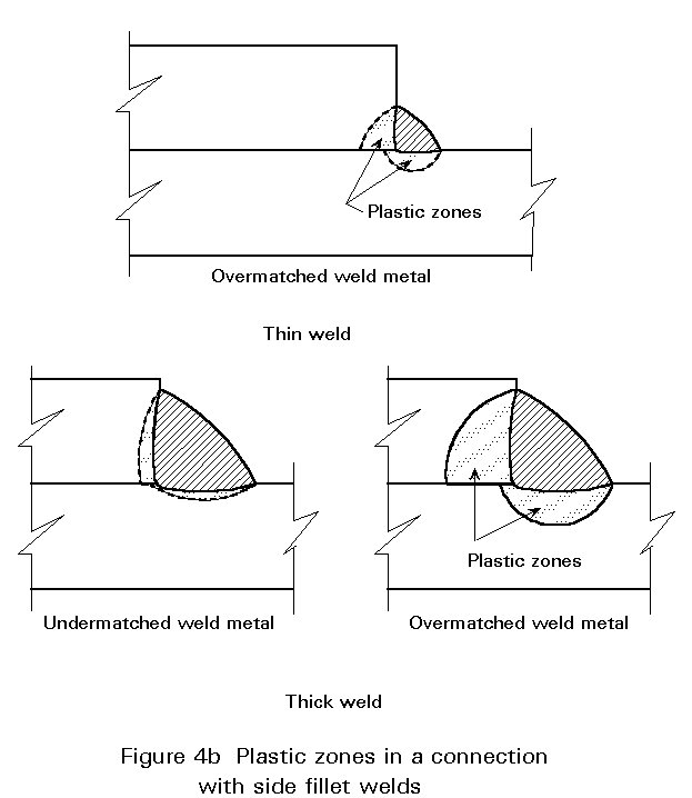
In longitudinally loaded welded connections an uneven load distribution occurs, similar to that just described for bolted connections. The highest stresses occur at the ends of the welds, see Figure 4.
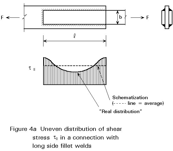
In this case also a uniform distribution of forces (stresses) may be assumed, provided that the deformation capacity is sufficient to allow for the required redistribution of stresses.
In a similar way as for long bolted connections, the differences in the stress distribution depend on the stiffness ratio of the connectors (welds) and the plates; the longer the connection the more uneven the stress distribution.
As with bolted connections, the deformation capacity is provided by the connector (the welds) and/or the adjacent plate material, see Figure 4a. Clearly the deformation capacity of a thick weld is greater than that of a thin weld.
The plastic zone and the deformation capacity of a weld are proportional to the weld thickness. In addition the ductility of the weld metal and the strength of the weld metal compared with the strength of the plate, have an influence on the deformation capacity.
If the yield strength of the weld metal is higher than the yield strength of the plate material, then plasticity occurs mainly in the plates. This is usually the case in common lower grades of steel (up to S275), where "overmatched" weld metals are applied (as required by Eurocode 3).
In higher strength steels it is sometimes difficult to have an overmatched weld metal with sufficient ductility. Then an "undermatched" weld metal with better ductility properties that is easier to weld may be considered. The consequence is that the plastic deformations tend to concentrate in the weld metal. The deformation capacity depends on (a) the size of the plastic zones in the weld and the adjacent plates and (b) on the ductility of the metal in these zones. If due to undermatching weld metal the plastic zones in the plate are small, then for the same deformation the strains in the weld metal are great. This means that the ductility requirements for undermatched weld metals should be higher than for overmatched weld metals. Therefore, it depends on ductility and yield strength of plate and available weld metals what situation is favourable: undermatched or overmatched weld metals.
The effect of the length of the weld on the distribution of stresses along the weld has been investigated by means of finite element calculations. To illustrate this the results of a numerical simulation carried out by Feder [2] are presented in Figure 5. The stress distribution and the shear deformations in side fillet welds have been determined for several values of the length l, see Figure 5. For the weld metal, a linear relation between the shear stress t1 and the relative displacement g = Dl/a is assumed. For other circumstances (geometry, cross-section of the plates, weld thickness, strength of weld metal and plate metal, etc), other results will be obtained.
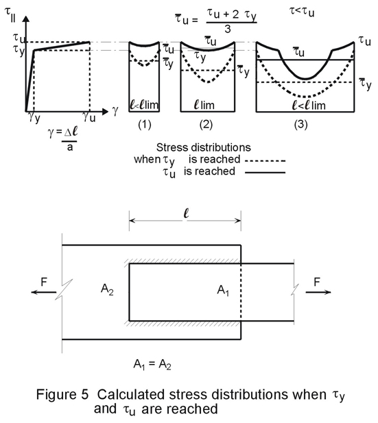
Figure 5 shows that up to a certain limited length of the weld (llim) yielding of the whole weld is possible. When the length of the weld is equal to llim, ty is reached in the middle of the weld, at the same time as the ultimate shear stress tu and the rupture displacement gu are attained at the ends. Then the average stress, tu, at the start of rupture is obtained by taking the average of a parabola as:
tu = (tu + 2ty)/3 (1-2)
For l > llim the central region of the weld will not have reached yield when the rupture starts at the ends of the weld.
Figure 6 gives results for a side fillet weld in steel S355 [2]. The members have the same cross-section area A1 = A2. The assumed t11- g diagram is also given in Figure 6.
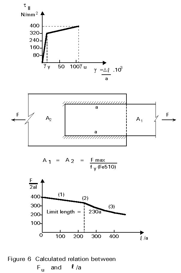
For the rupture strain (gu) the value 0,110 is taken. For a weld with 5 mm throat thickness, a displacement of 0,55 mm is obtained. A further assumption is that the plates do not yield at the gross cross-section when rupture of the weld occurs. Under these assumptions, llim=230aw, where aw is the throat thickness of the weld.
With increasing weld length the average shear stress at rupture decreases rapidly. When l > 300a, the stress in the middle of the weld remains zero!
According to Eurocode 3, the design resistance of a fillet weld in a lap joint should be reduced by a factor bLw.1 to allow for the effects of non- uniform distribution of stress along its length when it is longer than 150a according to the relationship:
b
Lw.1 = 1,2 - 0,2where Lj is the overall length of the lap joint in the direction of force transfer. In practice, lap joints with fillet welds longer than 100a or 150a are seldom used (for a = 5 mm, a length 150 a means 750 mm!).
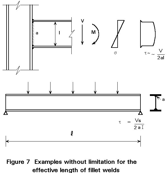
Of course, when the distribution of applied loads on the weld is evenly distributed along the weld, the above limitation does not apply. Examples are the welds between the web and the flange of welded beams and the connection of the web of a beam to a column, see Figure 7.
The design of weld groups (Figure 8) is tackled by considering the strength of the individual welds.
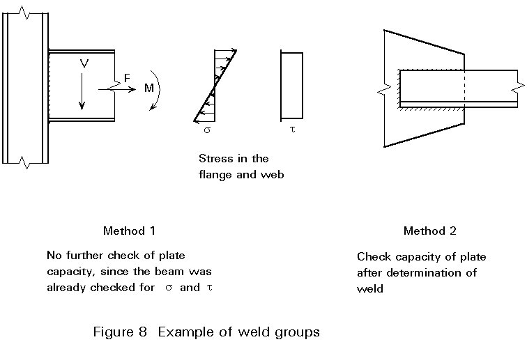
For this, two approaches based on the design assumptions of Clause 6.1.4 of Eurocode 3 can be followed:
The calculation based on the stresses in the parent material is easier and quicker than the second method. The stresses in the vicinity of the weld can be directly obtained from the structural design calculations. Because of the direct link between the analysis for the parent material and that of the welds, it is clear that the stresses in the weld are consistent with those in the parent material. Of course, it is necessary that in determining the stresses in the parent material, the stresses must be consistent with other parts in the connection (Lecture 11.4.1 Section 2.2 and Figure 2). Use of the first method is recommended.
However, there are cases where the first method cannot be applied because the stresses in the adjacent parent material cannot be simply determined and the second method must be used. Examples are:
In a double fillet weld shown in Figure 9, the following stresses act on the throat area (see also Lectures 11.2.2 and 11.2.3).
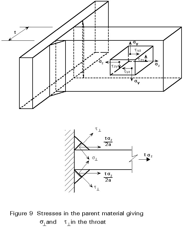
s^ = t^ = {0,5tsz 0,5Ö2}/a = [t/(2aÖ2)]sz (1-4)
t// = (t/2a)tzy (1-5)
With the alternative method of Annex M of Eurocode 3 it follows:
(t/2a)Ö[sz2/2 + 3sz2/2 + 3tzy2] £ fu/(bwgMw)
or:
(t/2a)Ö[2sz2 + 3tzy2] £ fu/(bwgMw) (1-6)
The second requirement s^ £ fu/gMw is only decisive if t^ is small, i.e. if the resultant force is oblique to the plate.
If in the parent material only sz is present then it follows:
a ³ (sz/fu)(bwgMw)t/Ö2 (1-7)
For S235: a ³ 0,71(sz/ fu)t (1-8)
For S355: a ³ 0,80(sz/ fu)t (1-9)
If the theory of plasticity is used for the design of the structure and the connection is located at a point where a plastic hinge may develop, then the minimum throat thickness must be based on sz = fy:
This gives for S235: a ³ 0,46 t (1-10)
and for S355: a ³ 0,55 t (1-11)
This requirement also applies for statically indeterminate structures that are designed using the theory of elasticity. It is important to remember that also in an elastic design, it is assumed (implicitly) that the members and the connections have sufficient deformation capacity to accommodate loads and stresses that usually are not explicitly taken into account in the design calculations (e.g. stresses due to uneven settlements of the supports; temperature loading; tolerance during fabrication; local overloading by live loads, etc.) and further to allow for the approximations inherent in the design models.
Therefore, it is necessary that the connected parts can yield before rupture of the welds.
When the design formulae of Eurocode 3 [1] are applied with sz = fy, then the real rupturing strength of the weld is at least the real rupturing strength of the plate. In other words, actual rupture occurs in the plate and not in the weld.
Thus, for the above requirement (yield in the plate before rupture in the weld), the design of the weld can be based on:
sz = (fyr/fur)fy (1-12)
where fyr is the measured yield strength and fur the measured ultimate strength of the plate material.
For the design values of the yield strength and the ultimate strength, it follows for S355:
sz = ![]() (1-13)
(1-13)
Because the actual value of fyr /fur can be higher than 0,70, it is required that:
If deformation capacity is necessary, the welds must be designed to transfer at least 80% of the yield force in the (weakest) connected member.
This requirement gives the following values for the minimum throat thickness of a double fillet as presented in Figure 9:
For S235: a ³ 0,37 t (1-14)
For S355: a ³ 0,44 t (1-15)
It should be noted that, using the mean stress method according to Eurocode 3, Chapter 6, greater throat thicknesses are found for end fillet welds. The difference is a factor of 1,22!
Thus the application of the mean stress method results in 1,222=1,5 times more weld metal than necessary.
This method must be applied if the first method is not applicable. For the determination of the strength of a weld group, the design values for the strength of the separate welds may be added, provided that the equilibrium requirements are fulfilled.
This approach is based on the assumption that the welds can yield to permit the redistribution of stresses necessary to accommodate local overloading. In other words, the welds must posses sufficient deformation capacity.
To gain some idea of the deformation capacity of welds under various loading combinations, tests [3] have been carried out as indicated in Figure 10. In these tests, the welds were thin compared with the plates in order to ensure yielding in the welds and not in the plates. The measuring length lo is given in Figure 10. The deformation of the plates was subtracted from the measured values, to obtain the deformation of the weld and the parent material in the direct vicinity of the weld, see Figure 4a.
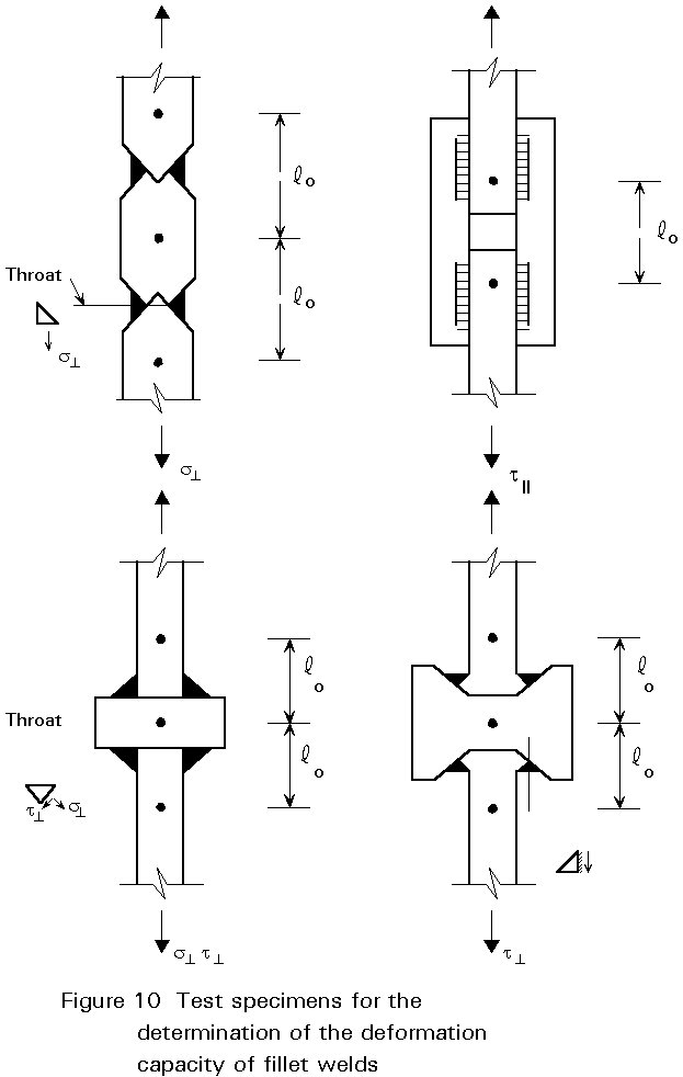
As already discussed, it appears that the deformation (mm) at the same stress in the weld is proportional to the throat thickness. Thus, when the thickness of a weld is doubled, not only is its strength doubled, but also its deformation capacity. This is the reason why the deformations are given as Dl/a on the horizontal axis in Figure 11.
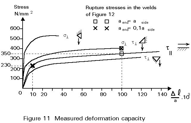
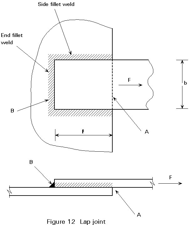
To demonstrate the importance of the above findings, the lap joint of Figure 12 is analyzed. Suppose that the plates are infinitely stiff compared with the stiffness of the welds. When the thicknesses of the end fillet weld and the side fillet welds are about the same, then, at the start of rupture (in the welds), the forces in all welds are practically equal to their ultimate load. This can easily be seen when the lines for t11 and s^ t^ are compared. With aside = aend and Dl for the side weld and end weld about the same, Dl/a is the same for side weld and end weld. Therefore, the ultimate strength of both welds may be added. This may not be true if one of the welds is very small, compared to the other. It can be concluded therefore, that the ultimate strength of the lap joint is equal to the sum of the ultimate strengths of the separate welds.
Now suppose that the throat thickness aend of the end fillet weld is only 10% of the throat thickness aside of the side fillet welds. At the start of rupture of the end fillet weld, the elongation Dl=100.10-3. aend=10.10-3 aside, see Figure 11.
The stress t11 corresponding to Dl/aside = 10 . 10-3 is about 230N/mm2, whilst the rupture strength for t11 is about 350N/mm2.
In this case, the ultimate strength of the lap joint is less than the sum of the ultimate strengths of the separate welds. As a result, it is recommended the following design rule is used:
Design recommendation
Try to give the end fillet weld and the side fillet weld the same thickness, and never design the end fillet weld to be less than 0,5 times the thickness of the side fillet welds.
The use of a thin weld at the front of the lap joint (point A in Figure 12), e.g. to prevent corrosion, must be avoided. If such a weld is necessary, then it should be given the same thickness as the other welds. This is particularly important because the plates are in reality not infinitely stiff compared with the welds. The required deformation capacity therefore is larger at the front (point A) than at the back of the lap joint (point B).
In Section 3.2 of Lecture 11.4.1 it was assumed that the bolt forces Ri are proportional to the displacement d = r q. This assumption is based on linear (elastic) behaviour of the connection. In the same way as for the design of welded connections, the theory of plasticity may be used also for bolted connections, see Figure 13.
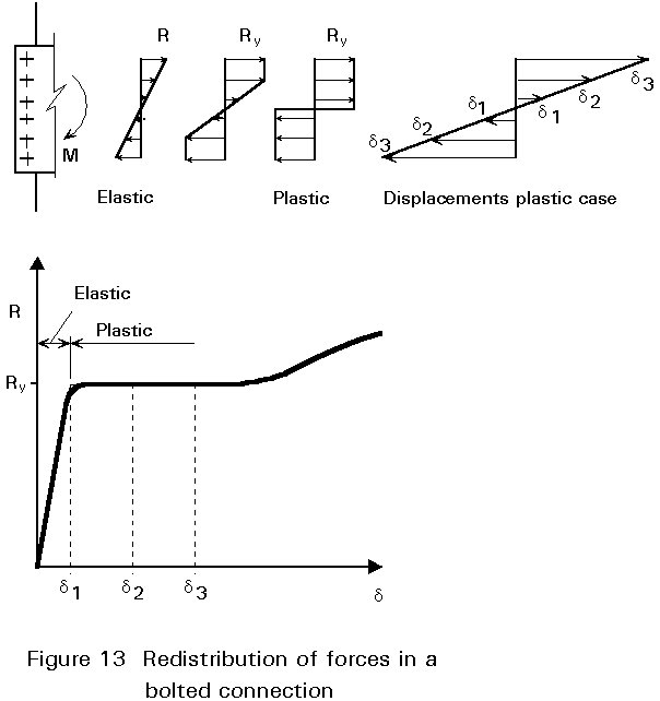
When the force on the connection increases, the force on the most heavily loaded bolt increases until the yield force Ry is reached. Then, with increasing displacement, the bolt force stays constant until strain hardening starts.
After the start of yielding at the most heavily loaded bolt, the bolt forces in the bolts which are nearer to the centre of rotation increase with increasing rotation. The moment increases until all bolts have reached the yield force.
From tests it may be concluded that the "plastic" moment of such bolted connections is normally reached at acceptable displacements. Therefore, in statically loaded structures, the design of such bolted connections may be based on the theory of plasticity.
In a plastic distribution of bolt forces, the centre of rotation does not need to be located at the centroid of the bolt group. This can be demonstrated as follows (compare Figures 14 and Lecture 11.4.1 Figure 12).
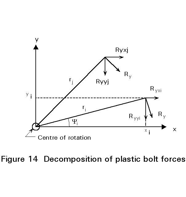
The "plastic" bolt force Ry may be distributed in the x-direction and y-direction:
Ry.xi = ![]() (1-16)
(1-16)
Ry.yi = ![]() (1-17)
(1-17)
If only bending moment is present, the following conditions must be fulfilled:
S
Ry.xi = 0 or: SS
Ry.yi = 0 or: SFor the general case, a direct solution for the position of the centre of rotation is not easily found, as was the case for an elastic bolt force distribution. Usually, the solution must be found by trial and error.
However, in practical cases, the bolt pattern is nearly always symmetric. For such cases it can be concluded that the centre of rotation lies on the intersection point of the axes of symmetry (which is also the centroid).
If the bolt group is subjected to a combination of shear force and bending moment, then the following approach can be followed.
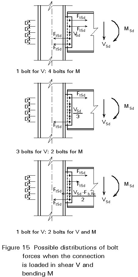
The bolts near the centre of rotation have a small moment arm, and therefore do not contribute very much to the moment resistance of the connection. It is economical therefore to use these bolts for the transfer of shear force V, and to use the outer bolts to resist the bending moment M.
Several possibilities are shown in Figure 15. The final choice depends on the proportions of the loads which must be carried: VSd and MSd.
The above design model is based on an elementary principle in the theory of plasticity:
Any distribution of forces, where the internal forces (bolt forces) are in equilibrium with the external forces in such a way that nowhere is the internal load-carrying resistance (the design resistance of the bolts) exceeded, gives a lower bound to the design resistance of the connection.
This principle is only valid if sufficient deformation capacity is available. In bolted connections this capacity can be assured by designing the bolts such that they are not the controlling item of the strength of the connection:
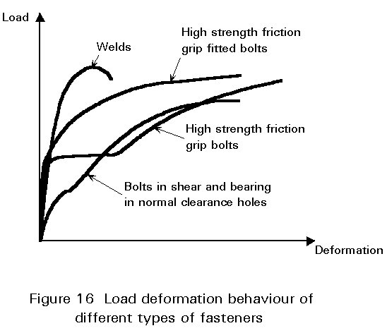
In general, the load deformation behaviour of different fasteners is such that their design resistances are reached at different deformations, see Figure 16. For this reason the use of more than one type of fastener in the design calculations is not normally allowed. In this respect the deformation capacity of the types of fastener used is an important factor.
In the case of welds acting in combination with preloaded bolts that are preloaded after welding is completed, the design resistances are reached at about the same deformation. Therefore, in this case it is permissible to add the design resistances of the preloaded bolts and the welds when determining the design resistance of the connection.
For all other arrangements only one type of fastening may be assumed to be "active" and all load must be transferred by this e.g. for a connection made originally with bolts that must be strengthened to withstand a higher load the welds must be designed to carry the whole of the load (not just the additional part).
i. for bolts in shear and bearing, ensure that bearing governs.
ii. for bolts in tension, ensure that yield of the plates in tension governs.
[1] Eurocode 3: "Design of Steel Structures" ENV 1993-1-1: Part 1.1, General rules and rules for buildings, CEN, 1992.
[2] Feder, D. and Werner, G., Ansätze zur Traglastberechnung von Schweissverbindungen des Stahlbaus. Schweissen und Schneiden, 29 (1977), Heft 4.
[3] Ligtenberg, F. K. and Van Melle, F., Onderzoek naar de vervorming van statisch belaste hoeklassen. Heron 12 (1964) No. 1 (Dutch). Investigation in the deformations of Statically Loaded Fillet Welds.