ESDEP WG 15A
STRUCTURAL SYSTEMS: OFFSHORE
To introduce the functional requirements; to identify major interfaces with the process, equipment, logistics, and safety; to introduce the structural concepts for jacket and gravity based structure (GBS) topsides; to elaborate on structural design for deck floors.
Lectures 1A & 1B: Steel Construction
Lecture 2.4: Steel Grades and Qualities
Lecture 2.5: Selection of Steel Quality
Lectures 3.1: General Fabrication of Steel Structures
Lecture 6.3: Elastic Instability Modes
Lecture 7.6: Built-up Columns
Lectures 8.4: Plate Girder Behaviour & Design
Lectures 11.2: Welded Connections
Lecture 12.2: Advanced Introduction to Fatigue
Lectures 15A: Structural Systems - Offshore
The topside lay-out is discussed, referring to API-RP2G [1], and to general aspects of interface control and weight control.
The different types of topside structures (relevant to the type of substructure, jacket or GBS) are introduced and described. These types are:
Floor concepts are presented and several aspects of the plate floor design are addressed.
This lecture deals with the overall aspects of the design of offshore topsides.
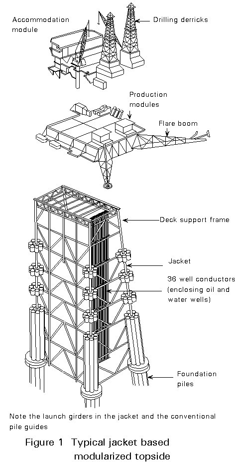
The topside of an offshore structure accommodates the equipment and supports modules and accessories such as living quarters, helideck, flare stack or flare boom, microwave tower, and crane pedestals.
The structural concept for the deck is influenced greatly by the type of substructure (jacket or GBS) and the method of construction, see Figures 1 and 2.
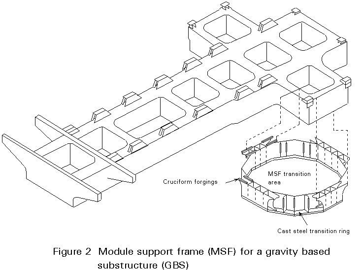
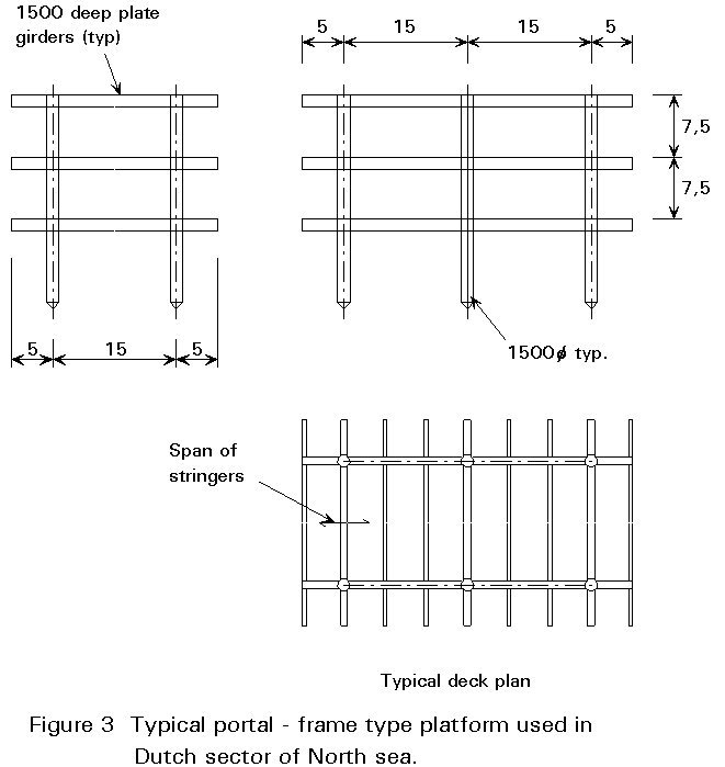
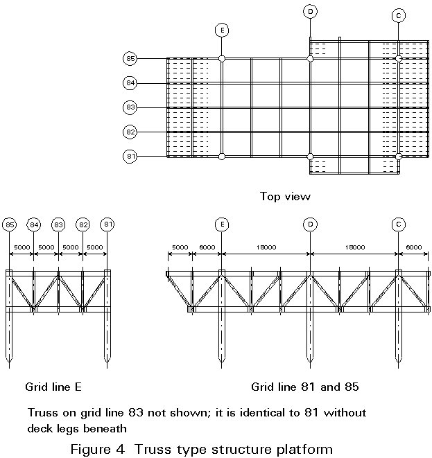
Heavy decks, over 10,000 tons, are provided with a module support frame onto which a number of modules are placed. Smaller decks, such as those located in the southern North Sea, are nowadays installed complete with all equipment in one lift to minimize offshore hook-up. Most of this lecture refers to this type of integrated deck such as is shown in Figures 3 and 4.
The selection of the concept for the structural deck is made in close cooperation with the other disciplines.
The first step in developing a new design concept is to consider all the requirements for the deck structure. The design requirements and their impact on the structural system are discussed below.
The lay-out of the deck is influenced by the type of hydrocarbon processing to be undertaken.
The area required for the equipment, piping and cable routings, the vertical clearance as well as the access/egress requirements determine the deck area and deck elevations.
The elevation on the lowest decks depends on the environmental conditions. The elevation of the cellar deck, i.e. the lowest deck, is based on the maximum elevation of the design wave crest, including tide and storm sway, plus an air gap of 1,5m minimum.
The vertical distance between the decks of the topside is generally in the range 6 - 9m in the North Sea.
Consideration of the prevailing wind direction is very important in determining the position of various components on the platform, such as the vent of the flare, cranes, helideck; and the logistic and safety provisions.
The requirements for the various topside components are briefly described below, based on API-RP2G [1].
Wells: the position of the wells depends heavily on whether the wells will be drilled and worked with a separate cantilevered jack-up rig or with a platform-based rig. In the first case the wells must be close to the platform edge and require significant deck area above free of obstacles. In the second case a pair of heavy beams to support the drill rig must be provided.
Equipment, piping and cable-supports: all devices to treat the oil or gas shall comply with the requirements of API-RP2G [1].
Living quarters and helideck: the helideck should be in the vicinity of the living quarters to enable fast evacuation. Usually the helideck is located in the obstacle free area on top of the living quarters.
Gas compressor module: the pressure in gas reservoirs declines due to production. Future compression may be needed in order to achieve acceptable gas flow through the export pipeline.
Water or gas injection module: oil production declines after some years of operation. The reservoir then requires stimulation by, for example, injection of water.
Deck crane: the location of the crane should be selected so as to obtain maximum deck coverage and to enable the crane operator to keep eye contact with the lifted object and the supply vessel. The location of the deck crane should be outside the obstacle free area of the helideck and should not interfere with future facilities.
Vent/flare boom or stack: a vent discharges gaseous products in the air without burning them; a flare discharges and burns these products. Both vents and flares should be located outside hazardous areas and away from the helideck. The tip shall exceed the elevation of the helideck by at least 100 feet. Heat radiation shall be checked.
Microwave tower: A high mounting is required to provide obstacle free support for microwave antennae. A stiff support is required in order to comply with the stringent deflection criteria.
Survival capsules and man-overboard crane: the supporting structures for these items usually cantilever from the main structure. Shock loading and dynamic amplification increases the support reactions during operation.
Walkways, ladders and stairs: these items should be kept obstacle free, be non-slippery and have sufficient width to allow evacuation of personnel on stretchers.
Cladding, walls, doors and louvres: the type of cladding depends on the operational requirements and the preference of the oil company. For safety reasons, walls and doors may have to satisfy specified explosion and fire resistance requirements. Louvres may be used to allow natural ventilation, whilst preventing entry of rain, snow and birds.
Lay down areas for equipment, spares and consumables: these areas are provided by cantilevering from the main structure in order to allow access to the lower deck levels by the deck crane, without providing hatches through the decks.
Hatches: access to the lower decks within reach of the crane is required to enable maintenance, repair and platform modification. The hatches should be identified early in the design.
Risers, caissons, sumps: the riser section of the pipeline rises from the seabed to the deck. It introduces vertical and horizontal loads (environmental and operational) in the deck structure. Caissons for pumps and sumps for discharge are hung from the cellar deck and introduce significant vertical and horizontal loads in the deck.
Drainage provisions: provision is required for spillage in drip pans under the equipment and for collecting oil-polluted rainwater to prevent spilling into the sea.
Deck penetrations: pipes connecting process-items on different decks and, vessels, cable routings, etc. can require significant areas to be clear of structural members. The major penetrations should be identified early in the design and coordinated with major structural members.
Other provisions: items such as monorails and inspection gangways may also be required.
In Lecture 15A.3 the different types of loads have been identified and partly quantified.
Dead weight, tankful live load and wind load are discussed here. Dead weight includes the weight of structure, equipment, piping, cables, machinery, and architectural outfitting. Tankful live load covers weight of potable water, diesel fuel, helifuel, glycol, methanol, well-kill mud, lubrication oil, waste, etc.
Live load also covers all sorts of miscellaneous loads such as bagged or palletized consumables, spare parts, maintenance equipment, etc.
The application of live load is typical for topsides. For design considerable engineering judgement is required concerning:
- direct loaded deck stringer
- deck beam
- deck truss
- deck leg
- jacket
- pile
- pile bearing resistance
For local strength, the walkways, escape routes, etc. are considered as non-occupied by equipment and are thus loaded by live load.
For overall strength, the walkways, escape routes, etc. are considered as occupied (kept clear for evacuation) and consequently no live load is applied.
Wind loads should be properly assessed. For overall structural integrity, the complex shape of the platform creates problems in assessing the effective area for wind load. Special elements such as communication towers and flare booms require consideration as wind sensitive structures.
To control the design process, weight engineering as explained in Section 2.5 below, shall be performed by the project management staff. Any structural analysis must be linked to the latest available information in the weight report. This requires that the load file for the structural analysis and the weight report are compatible with respect to total weight, weight distribution and centres of gravity.
The many functions of the topside result in the involvement of many disciplines in the design.
Due to the high cost of providing platform space, the facility must be designed to be very compact. This requirement leads to several major areas of interdisciplinary control.
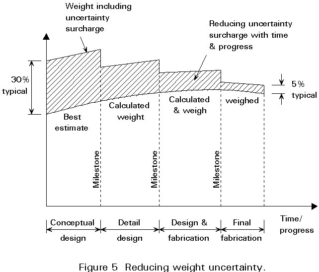
The weight of the overall facility as well as its major components is critical. Lack of weight control can lead to costly design changes as well as to major provisions in order to keep within the limits of the construction strategy.
Weight engineering consists of:
Weight prognosis is the methodology which applies an uncertainty surcharge as high as +30% in the conceptual design phase, to +5% in the final fabrication phase, see Figure 5.
The selection of the concept for the topside structure is the second step in the development of a structural system. The two possible basic alternatives: a truss type (Figure 4) or a portal-frame type without braces (Figure 3), are compared in Table 1.
Table 1 Comparison of concepts for main jacket-based structures
|
No. |
Item |
Truss type |
Frame type |
|
1. 2. 3. 4. 5. 6. 7. 8. 9. 10. 11. 12. |
Discipline non-interference Flexibility during construction Flexibility during operation Automated fabrication Construction depth Inspection Maintenance Weight of structure Strength reserve Potential for high strength steel Structural CAPEX Platform CAPEX |
- - - - ++ - - + + + + + |
++ ++ ++ ++ 0 ++ + 0 ++ ++ + ++ |
Note: ++ denotes greater benefit
-- denotes greater disadvantage
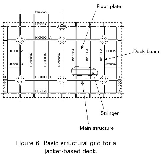
The selection of the topside main structure concept, truss or portal frame, is linked with the decision of the position of the longitudinal structure in the cross-section. In a 20-25m wide deck, trusses will generally be arranged in longitudinal rows: centre line and both outer walls (Figure 6).
In such decks, however, portal frames will be arranged in 2 longitudinal rows, approximately 14-16m apart, allowing floor cantilevers of approximately 5m (Figure 3).
Topsides of gravity based concrete structures (GBS) are quite different from the jacket based topsides, see Lecture 15A.1. The topside structure is an important element in the overall portal-type system. Gravity based substructures have been built with one to four shafts. A rectangular or a T-arrangement of four shafts has been adopted. The basic form is a modularized topside with a grid of heavy box girders.
A few elements only of the GBS-topside structural design are indicated below:
The material used at present is high strength steel typically of 355 MPa yield stress. There is a trend to use higher strength steel (420-460 MPa).
The concept for the floor-system in offshore structures is conventional: hot rolled beams, typically at 1000-1200mm centres, are covered by a chequered or flat steel plate 6-10mm thick.
The options are:
The conventional steel floor contributes approximately half of the weight of the steel structure of an offshore deck.
Steel gratings, especially with the plate type, could gain increased application as their weight per sq.m. is attractive.
Aluminium has attracted much interest recently; current development in Norway will show its real potential.
Orthotropic decks in steel have found application in helidecks. Further study is required to assess their actual feasibility for floors of offshore modules.
Corrugated steel plate (approximately 1-3mm thick) as sub-flooring has been used in living quarters.
In summary, the floor concept used for a typical floor of an offshore deck of a module is a conventional steel floor or steel grating.
The floor panel, defined as the assembly of the floor plate and the stringer, can be connected to the overall structure in two ways:
All elevations and overhead clearances are involved in the choice of arrangement. Clearances are very important for equipment height, pipe routing, pipe stress, cable routing, etc. The single most important structural aspect is the amount of prefabrication that can be carried out away from the main fabrication yard. The cost is also a very important factor.
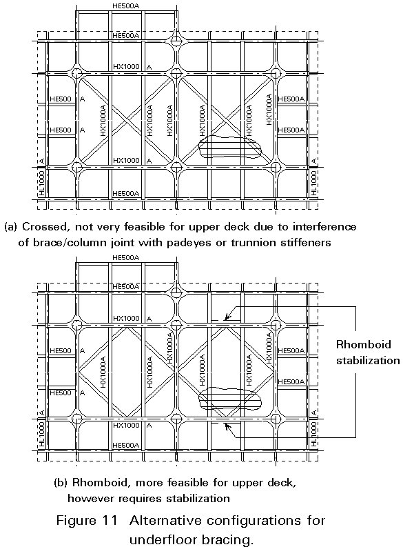
The deck structure requires lateral stabilization of each floor with respect to:
There are essentially two options for floor stabilization:
There is a clear preference for the stabilization by the floor plate. Where underfloor bracing is adopted, there are two configuration options (see Figure 11). The rhomboid solution should be chosen for the upper deck, due to congestion at the column by the padeyes for lifting. The underfloor bracing under a plate floor does create a very unclear structural situation. The bracing is assumed completely to perform the stabilizing function, but in practice the floor plate is much too stiff to allow that. It is common practice in the structural analysis for underfloor bracing to neglect completely the floor plate.
The selection of the main deck dimensions have been considered above in relation to lay-out requirements.
The interactive process of conceptual design of the jacket and deck yields the spacing of the columns. In the Dutch sector of the North Sea, transverse column spacings are typically 9m for a wellhead platform to 15m for a production platform. Longitudinally spacings are typically 15m.
Next decisions are made on:
The structural concept is then complete.
A principle for economic design of steel structures is that the load-paths should be short.
For a floor design of a production deck typical dimensions are:
Structural item Typical span
These components are identified in Figure 6.
Design
Options are to choose between flat plate, chequered plate or tear plate. Another option for providing slip resistance is to coat with a sand finish. The floor plate thickness is usually 8-10mm and 6mm for lighter loaded floors, although welding distortion may rule out the 6 mm thickness.
In practice the floor plate acts as horizontal bracing between the columns.
Special attention is required to ensure that all welds between the floor plate and the underlying structure do not form brittle points. Failure of such welds could lead to crack initiation in the rest of the structure.
The same attention applies to the buckling of the floor plate by stresses which are picked up unintentionally.
Strength of Floor Plate
The strength of the floor plate is very high both for uniform as well as concentrated loads.
Elastic, small-deflection theory provides uneconomical conservative results.
API-RP2A (2) does not specify live loads. They are specified by the operator.
For main decks generally accepted figures are:
p = 20kN/sqm, or
F = 10-25 kN on a 0,3 x 0,3m load area
Det Norske Veritas [3] presents an expression for the required plate thickness t, which incorporates membrane effects and is of special interest for design for local loads.
Equipment and containers are regularly offloaded by the crane in some deck areas, such as lay-down areas and food container platforms. An increased plate thickness may be required in these areas due to larger concentrated loads (1).
The typical stringer for a production platform is an IPE 240-270 or HE 240-280A profile positioned at approximately 1m centres and spanning 5m.
It is important to choose, especially for stacked floor panels, a profile which allows selection of heavier sections with practically identical depth to accommodate local heavy equipment.
Designers should avoid choosing deeper sections or reinforcing them to accommodate late extra load requirements by welding another section underneath. Interference with small diameter, hard piping or with cable trays then is quite likely.
Joining floor plate and stringers requires welding. Intermittent welding is generally not accepted. A continuous thin weld (a = 4 mm) is usually specified. The shear in this weld is generally quite low.
The joint between the stringer and the deck beam differs with the floor panel concept chosen.
If the top of the deck beam becomes inaccessible for maintenance, some operators will require seal plates to be welded between the deck beam and the floor plate. This is quite expensive. A typical joint is depicted in Figure 7.
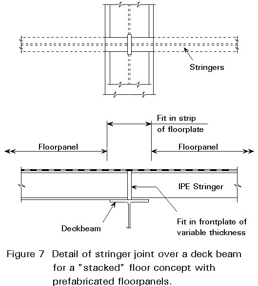
The decision on the type of stringer joint should preferably be made prior to material ordering.
Deck beams supporting the floor panels or providing direct support to major equipment are generally provided as HE 800-1000 beams, though HL 1000 (400mm wide) or HX 1000 (450mm wide) are also used for heavier loads or greater spans.
The major joint in the deck beam is that with the main structure.
The joint configuration is strongly determined by the prefabrication concept and elevation of the flanges. It is different for the stacked and for the flush concept.
Stacked Floor Concept
Figures 8 and 9 illustrate the problems.

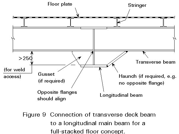
For the full stacked concept (Figure 9), where both transverse and longitudinal main beam are positioned lower, welding of the top flanges is straightforward.
The lower flange, typically 40mm thick, can only be welded to the web, typically 20-25mm thick, if alignment of both flanges is ensured.
The lower flange of the main structure should be at least 250mm underneath, to enable back welding of the root.
For the less suitable partially stacked concept (Figure 8), where only the transverse main beam is positioned lower, connection for the top flange of the transverse deck beam is more difficult. Direct welding of the top flange of the deck beam to the web should be rejected. Options are shown in Figure 9 with detail (a) haunching and detail (b) slotting the top flange through the web.
Again it is apparent that a decision on joint configuration is required prior to material ordering.
Flush Floor Concept
Detailing is dependent of the prefabrication policy.
If the deck panel is prefabricated as an assembly of plate, stringer and deck beam, the detail shown in Figure 10a is the more appropriate.
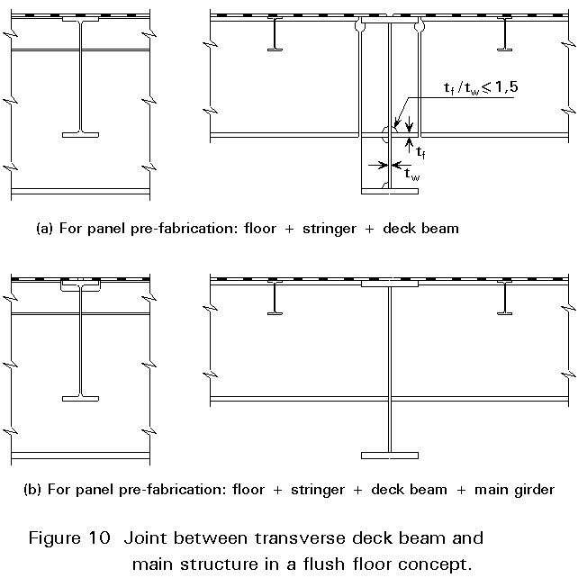
To allow top flange welding a strip of the floor plate is fitted and welded last.
If the deck panel is fabricated as an assembly of plate and stringer only, the detail Figure 10b will be the most feasible.
In Section 3.5 the preference for the floor plate to act as horizontal bracing was indicated.
If however separate bracing members are required, the elevation must be chosen carefully. The bracing members have to pass with sufficient clearance under the stringers, penetrate the web of the deck beams at sufficient distance from the lower flange. They also require good access for welding of the joint.
These requirements generate the elevation and the maximum feasible diameter of the brace (Figure 11).
Horizontal bracing can easily clash with vertical piping and major hatches.
Assembly of the braces is generally quite cumbersome.
integrated deck.
module support frame.
modules.
[1] API-RP2G: Production facilities on offshore structures.
American Petroleum Institute 1 ed. 1974.
Presents the basic requirements.
[2] API-RP2A: Recommended practice for planning, designing and constructing fixed platforms.
American Petroleum Institute, 18th ed., 1989.
The structural offshore code governs the majority of platforms.
[3] DNV: Rules for the classification of steel ships.
Part 5, Chapter 2.4.C, Permanent decks for wheel loading.
Det Norske Veritas.
Practical approach for economic floor plate design under static load.
BOSS Conference 1988 Trondheim, pp 1001-1014.
Floor and roof plate behaviour under accidental loading.
IRO Journal, nr. 38, 1987, pp 3-9.
Presents a recent example for a portal-framed topside.
9th. OMAE conference Houston 1990, paper 90-335.
Most recent presentation on GBS topside structure.
Good background to theory of plated structures.