ESDEP WG 15A
STRUCTURAL SYSTEMS: OFFSHORE
To identify the basic vocabulary, to introduce the major concepts for offshore platform structures, and to explain where the basic structural requirements for design are generated.
None.
The lecture starts with a presentation of the importance of offshore hydro-carbon exploitation, the basic steps in the development process (from seismic exploration to platform removal) and the introduction of the major structural concepts (jacket-based, GBS-based, TLP, floating). The major codes are identified.
For the fixed platform concepts (jacket and GBS), the different execution phases are briefly explained: design, fabrication and installation. Special attention is given to some principles of topside design.
A basic introduction to cost aspects is presented.
Finally terms are introduced through a glossary.
Offshore platforms are constructed to produce the hydrocarbons oil and gas. The contribution of offshore oil production in the year 1988 to the world energy consumption was 9% and is estimated to be 24% in 2000.
The investment (CAPEX) required at present to produce one barrel of oil per day ($/B/D) and the production costs (OPEX) per barrel are depicted in the table below.
|
Condition |
CAPEX $/B/D |
OPEX $/B |
|
Conventional |
||
|
Average |
4000 - 8000 |
5 |
|
Middle East |
500 - 3000 |
1 |
|
Non-Opec |
3000 - 12000 |
8 |
|
Offshore |
||
|
North Sea |
10000 - 25000 |
5 - 10 |
|
Deepwater |
15000 - 35000 |
10 - 15 |
World oil production in 1988 was 63 million barrel/day. These figures clearly indicate the challenge for the offshore designer: a growing contribution is required from offshore exploitation, a very capital intensive activity.
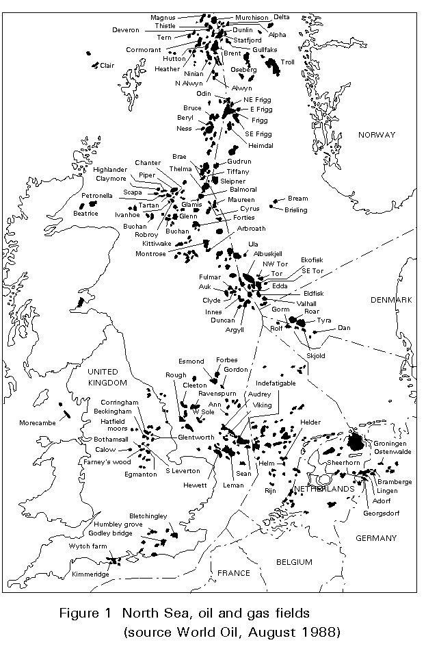
Figure 1 shows the distribution of the oil and gas fields in the North Sea, a major contribution to the world offshore hydrocarbons. It also indicates the onshore fields in England, the Netherlands and Germany.
The overwhelming majority of platforms are piled-jacket with deck structures, all built in steel (see Slides 1 and 2).
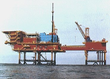
Slide 1 : Jacket based platform - Southern sector North Sea
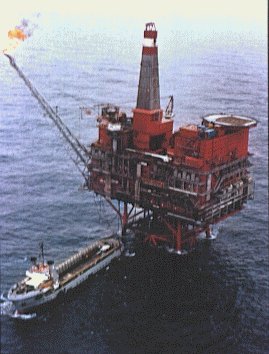
Slide 2 : Jacket based platform - Northern sector North Sea
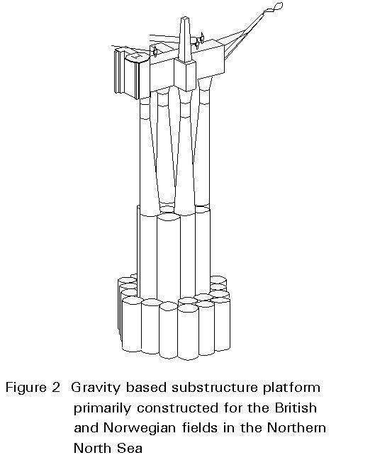
A second major type is the gravity concrete structure (see Figure 2), which is employed in the North Sea in the Norwegian and British sectors.
A third type is the floating production unit.
The offshore environment can be characterized by:
The topside structure also must be kept clear of the wave crest. The clearance (airgap) usually is taken at approximately 1,50 m, but should be increased if reservoir depletion will create significant subsidence.
The environment as well as financial aspects require that a high degree of prefabrication must be performed onshore. It is necessary to design to limit offshore work to a minimum. The overall cost of a man-hour offshore is approximately five times that of an onshore man-hour. The cost of construction equipment required to handle loads, and the cost for logistics are also a magnitude higher offshore.
These factors combined with the size and weight of the items, require that a designer must carefully consider all construction activities between shop fabrication and offshore installation.
Structural design has to comply with specific offshore structural codes. The worldwide leading structural code is the API-RP2A [1]. The recently issued Lloyds rules [2] and the DnV rules [3] are also important.
Specific government requirements have to be complied with, e.g. in the rules of Department of Energy (DoE), Norwegian Petroleum Direktorate (NPD). For the detail design of the topside structure the AISC-code [4] is frequently used, and the AWS-code [5] is used for welding.
In the UK the Piper alpha diaster has led to a completely new approach to regulation offshore. The responsibility for regulatory control has been moved to the Health and Safety Executive (HSE) and the operator has to produce a formal safety assessment (TSA) himself instead of complying with detailed regulations.
Government authorities require that recognized bodies appraise the aspects of structural integrity and issue a certificate to that purpose.
The major certification bodies are:
Their requirements are available to the designer [2, 3, 6, 7, 8].
Insurance companies covering transport and installation require the structures to be reviewed by warranty surveyors before acceptance. The warranty surveyors apply standards, if available, on a confidential basis.
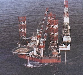
The different requirements of an offshore platform and the typical phases of an offshore development are summarized in [9]. After several initial phases which include seismic field surveying, one or more exploration wells are drilled. Jack-up drilling rigs are used for this purpose for water depths up to 100 - 120 m; for deeper water floating rigs are used. The results are studied and the economics and risks of different development plans are evaluated. Factors involved in the evaluation may include number of wells required, fixed or floated production facilities, number of such facilities, and pipeline or tanker off-loading.
As soon as exploitation is decided and approved, there are four main technical activities, prior to production:
The drilling and construction interaction is described below for two typical fixed platform concepts.
First the jacket is installed. The wells are then drilled by a jack-up drilling unit standing close by with a cantilever rig extending over the jacket. Slide 3 shows a jack-up drilling unit with a cantilever rig. (In this instance it is engaged in exploratory drilling and is therefore working in isolation.)
Slide 3 : Cantilevered drilling rig: Self-elevating (jack-up) exploration drilling platform.
Design and construction of the topside are progressed parallel to the drilling, allowing production to start soon after deck installation. For further wells, the jack-up drilling unit will be called once again and will reach over the well area of the production deck.
As an alternative to this concept the wells are often accommodated in a separate wellhead platform, linked by a bridge to the production platform (see Slide 1).
The wells are drilled from a drilling rig on the permanent platform (see Slide 2). Drilling starts after the platform is built and completely installed. Consequently production starts between one and two years after platform installation.
In recent years pre-drilled wells have been used to allow an earlier start of the production. In this case the platform has to be installed exactly above the pre-drilled wells.
Jackets, the tower-like braced tubular structures, generally perform two functions:
The installation methods for the jacket and the piles have a profound impact on the design.
The jacket foundation is provided by open-ended tubular steel piles, with diameters up to 2m. The piles are driven approximately 40 - 80 m, and in some cases 120 m deep into the seabed.
There are basically three types of pile/jacket arrangement (see Figure 3):
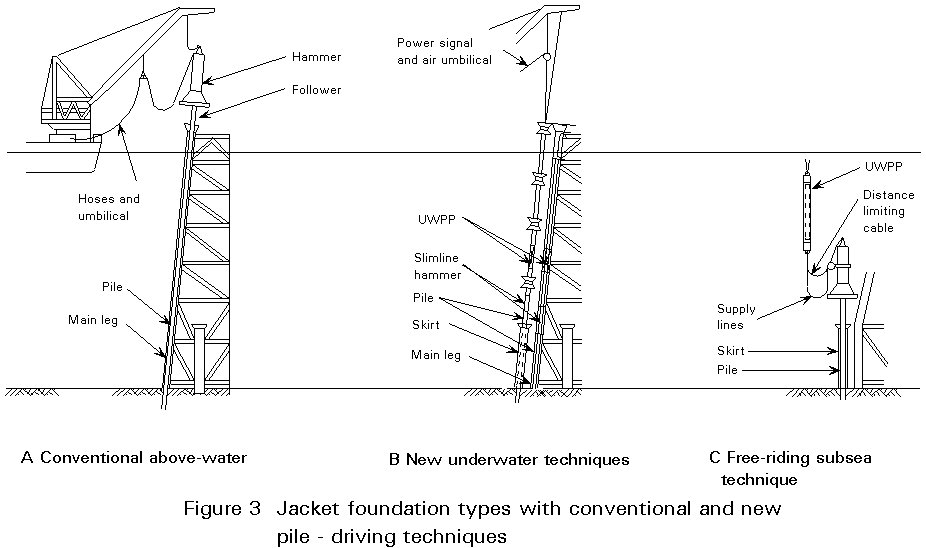
Pile-through-leg concept, where the pile is installed in the corner legs of the jacket.
Skirt piles through pile sleeves at the jacket-base, where the pile is installed in guides attached to the jacket leg. Skirt piles can be grouped in clusters around each of the jacket legs.
Vertical skirt piles are directly installed in the pile sleeve at the jacket base; all other guides are deleted. This arrangement results in reduced structural weight and easier pile driving. In contrast inclined piles enlarge the foundation at the bottom, thus providing a stiffer structure.
Axial load resistance is required for bearing as well as for tension. The pile accumulates both skin friction as well as end bearing resistance.
Lateral load resistance of the pile is required for restraint of the horizontal forces. These forces lead to significant bending of the pile near to the seabed.
Number, arrangement, diameter and penetration of the piles depend on the environmental loads and the soil conditions at the location.
The most usual form of corrosion protection of the bare underwater part of the jacket as well as the upper part of the piles in soil is by cathodic protection using sacrificial anodes. A sacrificial anode (approximate 3 kN each) consists of a zinc/aluminium bar cast about a steel tube and welded on to the structures. Typically approximately 5% of the jacket weight is applied as anodes.
The steelwork in the splash zone is usually protected by a sacrificial wall thickness of 12 mm to the members.
The major functions on the deck of an offshore platform are:
There are basically two structural types of topside, the integrated and modularized topside which are positioned either on a jacket or on a concrete gravity substructure.
There are four structural concepts in practice. They result from the lifting capacity of crane vessels and the load-out capacity at the yards:
Slide 4 shows an integrated deck (though excluding the living quarters and helideck) being moved from its assembly building.
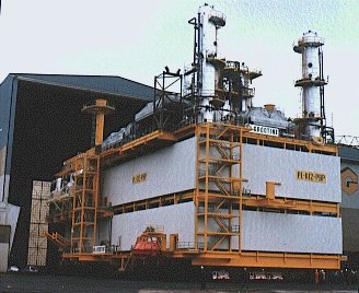
Slide 4 : Integrated topside during load out
For the smaller decks, up to approximately 100 MN weight, the support structure consists of trusses or portal frames with deletion of diagonals.
The moderate vertical load and shear per column allows the topside to be supported by vertical columns (deck legs) only, down to the top of the piles (situated at approximately +4 m to +6 m L.A.T. (Low Astronomic Tide).
A major modularized topside weighs 200 to 400 MN. In this case the MSF is a heavy tubular structure (Figure 4), with lateral bracing down to the top of jacket.

The topsides to be supported by a gravity-based substructure (see Figure 2) are in a weight range of 200 MN up to 500 MN.
The backbone of the structure is a system of heavy box-girders with a height of approximately 10 m and a width of approximately 12 - 15 m (see Figure 5).
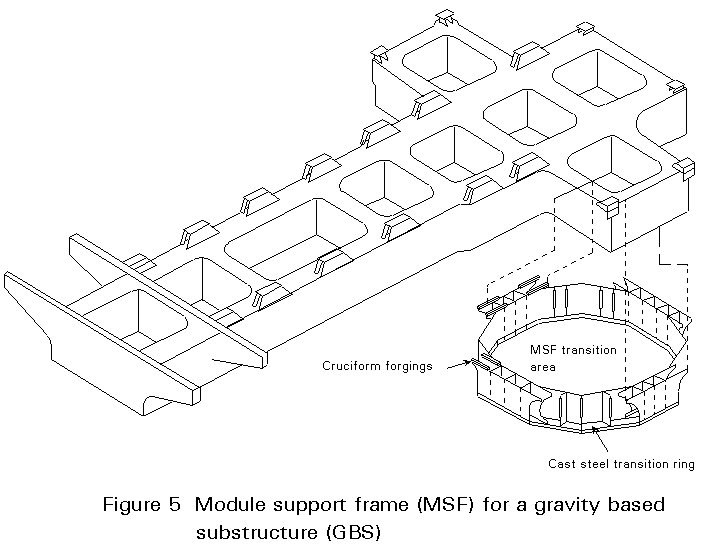
The substructure of the deck is rigidly connected to the concrete column and acts as a beam supporting the deck modules. This connection introduces wave-induced fatigue in the deck structure. A recent development, foreseen for the Norwegian Troll platform, is to provide a flexible connection between the deck and concrete column, thus eliminating fatigue in the deck [10].
Equipment modules (20-75 MN) have the form of rectangular boxes with one or two intermediate floors.
The floors are steel plate (6, 8 or 10 mm thick) for roof and lower floor, and grating for intermediate floors.
In living quarter modules (5-25 MN) all sleeping rooms require windows and several doors must be provided in the outer walls. This requirement can interfere seriously with truss arrangements. Floors are flat or stiffened plate.
Three types of structural concepts, all avoiding interior columns, can be distinguished:
The design of offshore structures has to consider various requirements of construction relating to:
A documented construction strategy should be available during all phases of the design and the actual design development should be monitored against the construction strategy.
Construction is illustrated below by four examples.
The jacket is built in the vertical (smaller jackets) or horizontal position (bigger jackets) on a quay of a fabrication site.
The jacket is loaded-out and seafastened aboard a barge. At the offshore location the barge is moored alongside an offshore crane vessel.
The jacket is lifted off the barge, upended from the horizontal, and carefully set down onto the seabed.
After setting down the jacket, the piles are installed into the sleeves and, driven into the seabed. Fixing the piles to the jacket completes the installation.
The jacket is built in horizontal position.
For load-out to the transport barge, the jacket is put on skids sliding on a straight track of steel beams, and pulled onto the barge (Slide 5).
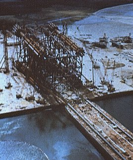
Slide 5 : Jacket being loaded onto barge by skidding
At the offshore location the jacket is slid off the barge. It immerses deeply into the water and assumes a floating position afterwards (see Figure 6).
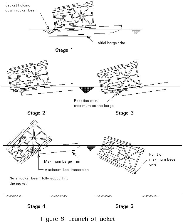
Two parallel heavy vertical trusses in the jacket structure are required, capable of taking the support reactions during launching. To reduce forces and moments in the jacket, rocker arms are attached to the stern of the barge.
The next phase is to upright the jacket by means of controlled flooding of the buoyancy tanks and then set down onto the seabed. Self-upending jackets obtain a vertical position after the launch on their own. Piling and pile/jacket fixing completes the installation.
The topside is assembled above the sea on a temporary support near a yard. It is then taken by a barge of such dimensions as to fit between the columns of the temporary support and between the columns of the GBS. The GBS is brought in a deep floating condition in a sheltered site, e.g. a Norwegian fjord. The barge is positioned between the columns and the GBS is then deballasted to mate with and to take over the deck from the barge. The floating GBS with deck is then towed to the offshore site and set down onto the seabed.
For topsides up to approximately 120 MN, the topside may be installed in one lift. Slide 6 shows a 60 MN topside being installed by floating cranes.
Slide 6 : Installation of 60MN K12-BP topside by floating crane
For the modularized topside, first the MSF will be installed, immediately followed by the modules.
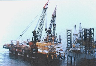
Lifting of heavy loads from barges (Slide 6) is one of the very important and spectacular construction activities requiring a focus on the problem when concepts are developed. Weather windows, i.e. periods of suitable weather conditions, are required for these operations.
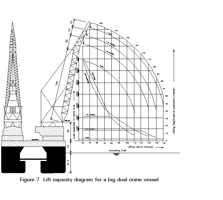
Lifting of heavy loads offshore requires use of specialized crane vessels. Figure 7 provides information on a typical big, dual crane vessel. Table 1 (page 16) lists some of the major offshore crane vessels.
For lifting, steel wire ropes in a four-sling arrangement are used which directly rest in the four-point hook of the crane vessel, (see Figure 8). The heaviest sling available now has a diameter of approximately 350 mm, a breaking load of approximately 48 MN, and a safe working load (SWL) of 16 MN. Shackles are available up to 10 MN SWL to connect the padeyes installed at the module's columns. Due to the space required, connecting more than one shackle to the same column is not very attractive. So when the sling load exceeds 10 MN, padears become an option.
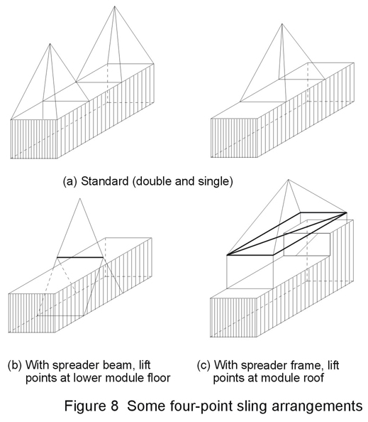
Table 1 Major Offshore Crane Vessels
|
Operator |
Name | Mode | Type | Lifting capacity (Tonnes) |
|
Heerema |
Thor |
Monohull |
Fix |
2720 |
|
Rev |
1820 |
|||
|
Odin |
Monohull |
Fix |
2720 |
|
|
Rev |
2450 |
|||
|
Hermod |
Semisub |
Fix |
4536 + 3628 = 8164 |
|
|
Rev |
3630 + 2720 = 6350 |
|||
|
Balder |
Semisub |
Fix |
3630 + 2720 = 6350 |
|
|
Rev |
3000 + 2000 = 5000 |
|||
|
McDermott |
DB50 |
Monohull |
Fix |
4000 |
|
Rev |
3800 |
|||
|
DB100 |
Semisub |
Fix |
1820 |
|
|
Rev |
1450 |
|||
|
DB101 |
Semisub |
Fix |
3360 |
|
|
Rev |
2450 |
|||
|
DB102 |
Semisub |
Rev |
6000 + 6000 = 12000 |
|
|
Micoperi |
M7000 |
Semisub |
Rev |
7000 + 7000 = 14000 |
|
ETPM |
DLB1601 |
Monohull |
Rev. |
1600 |
Notes:
Fix = Load capability with crane fixed.
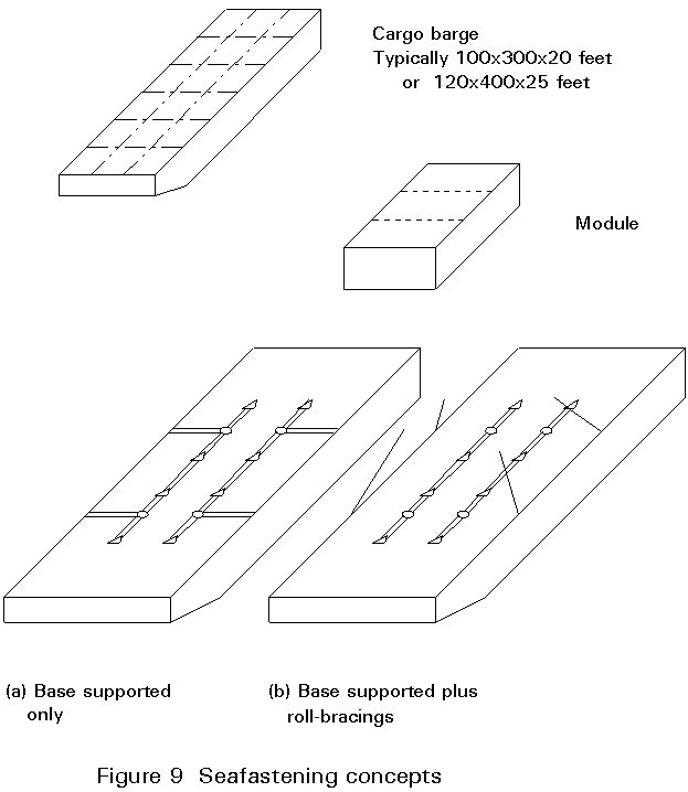
Transportation is performed aboard a flat-top barge or, if possible, on the deck of the crane vessel.
The module requires fixing to the barge (see Figure 9) to withstand barge motions in rough seas. The sea fastening concept is determined by the positions of the framing in the module as well as of the "hard points" in the barge.
For load-out three basic methods are applied:
Skidding is a method feasible for items of any weight. The system consists of a series of steel beams, acting as track, on which a group of skids with each approximately 6 MN load capacity is arranged. Each skid is provided with a hydraulic jack to control the reaction.
Specialized trailer units (see Figure 10) can be combined to act as one unit for loads up to 60 - 75 MN. The wheels are individually suspended and integrated jacks allow adjustment up to 300 mm.
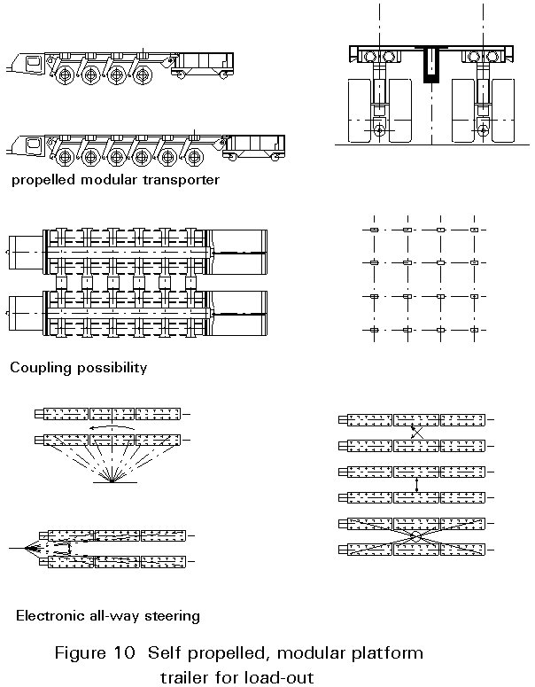
The load capacity over the projected ground area varies from approximately 55 to 85 kN/sq.m.
The units can drive in all directions and negotiate curves.
Load-out by shearlegs is attractive for small jackets built on the quay. Smaller decks (up to 10 - 12 MN) can be loaded out on the decklegs pre-positioned on the barge, thus allowing deck and deckleg to be installed in one lift offshore.
In recent years platform removal has become common. The mode of removal depends strongly on the regulations of the local authorities. Provision for removal should be considered in the design phase.
The majority of structural analyses are based on the linear theory of elasticity for total system behaviour. Dynamic analysis is performed for the system behaviour under wave-attack if the natural period exceeds 3 seconds. Many elements can exhibit local dynamic behaviour, e.g. compressor foundations, flare-stacks, crane-pedestals, slender jacket members, conductors.
Three types of analysis are performed:
All these analyses are performed on the complete and intact structure. Assessments at damaged structures, e.g. with one member deleted, and assessments of collision situations are occasionally performed.
The major phases of construction when structural integrity may be endangered are:
The economic feasibility of an offshore project depends on many aspects: capital expenditure (CAPEX), tax, royalties, operational expenditure (OPEX).
In a typical offshore field development, one third of the CAPEX is spent on the platform, one third on the drilling of wells and one third on the pipelines.
Cost estimates are usually prepared in a deterministic approach. Recently cost-estimating using a probabilistic approach has been developed and adopted in major offshore projects.
The CAPEX of an installed offshore platform topside amounts to approximately 20 ECU/kg.
The major elements in the CAPEX for an offshore platform are:
In the North Sea approximately 20 percent of OPEX are required for offshore inspection, maintenance and repair (IMR).
The amount to be spent on IMR over the project life can add up to approximately half the original investment.
IMR is the area in which the structural engineer makes a contribution by effort in design, selection of material, improved corrosion protection, accessibility, basic provisions for scaffolding, avoiding jacket attachments dangerous to divers, etc.
Deep water introduces a wide range of extra difficulties for the operator, the designer and constructor of offshore platforms.
Fixed platforms have recently been installed in water of 410 m. depth, i.e. "Bullwinkle" developed by Shell Oil for a Gulf of Mexico location. The jacket weighed nearly 500 MN.
The maximum depth of water at platform sites in the North Sea is approximately 220 m at present. The development of the Troll field situated in approximately 305 m deep water is planned for 1993.
In the Gulf of Mexico and offshore California several fixed platforms in water depths of 250 - 350 m are in operation (Cerveza, Cognac). Exxon has a guyed tower platform (Lena) in operation in 300 m deep water.
An option for deeper locations is to use subsea wells with flowlines to a nearby (approximately maximum 10 km) fixed platform at a smaller water depth. Alternatively subsea wells may be used with flexible risers to a floating production unit. Subsea wells are now feasible for 300 - 900 m deep water. The deepest wells have been developed off Brasil in moderate weather conditions.
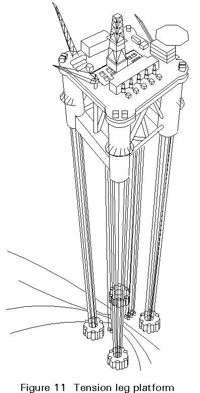
The tension leg platform (TLP) seems to be the most promising deepwater production unit (Figure 11). It consists of a semi-submersible pontoon, tied to the seabed by vertical prestressed tethers. The first TLP was Hutton in the North Sea and recently TLP-Jolliet was installed at a 530 m deep location in the Gulf of Mexico. Norwegian Snorre and Heidrun fields have been developed with TLPs as well.
AIR GAP Clearance between the top of maximum wave and underside of the topside.
CAISSONS See SUMPS
CONDUCTORS The tubular protecting and guiding the drill string from the topside down to 40 to 100m under the sea bottom. After drilling it protects the well casing.
G.B.S. Gravity based structure, sitting flatly on the sea bottom, stable through its weight.
HOOK-UP Connecting components or systems, after installation offshore.
JACKET Tubular sub-structure under a topside, standing in the water and pile founded.
LOAD-OUT The operation of bringing the object (module, jacket, deck) from the quay onto the transportation barge.
PADEARS (TRUNNIONS) Thick-walled tubular stubs, directly receiving slings and transversely welded to the main structure.
PADEYES Thick-walled plate with hole, receiving the pin of the shackle, welded to the main structure.
PIPELINE RISER The piping section which rises from the sea bed to topside level.
SEA-FASTENING The structure to keep the object rigidly connected to the barge during transport.
SHACKLES Connecting element (bow + pin) between slings and padeyes.
SLINGS Cables with spliced eyed at both ends, for offshore lifting, the upper end resting in the crane hook.
SPREADER Tubular frame, used in lifting operation.
SUBSEA TEMPLATE Structure at seabottom, to guide conductors prior to jacket installation.
SUMPS Vertical pipes from topside down to 5-10 m below water level for intake or discharge.
TOPSIDE Topside, the compact offshore process plant, with all auxiliaries, positioned above the waves.
UP ENDING Bringing the jacket in vertical position, prior to set down on the sea bottom.
WEATHER WINDOW
A period of calm weather, defined on basis of operational limits for the offshore marine operation.
WELLHEAD AREA Area in topside where the wellheads are positioned including the valves mounted on its top.
[1] API-RP2A: Recommended practice for planning, designing and constructing fixed offshore platforms.
American Petroleum Institute 18th ed. 1989.
The structural offshore code, governs the majority of platforms.
[2] LRS Code for offshore platforms.
Lloyds Register of Shipping.
London (UK) 1988.
Regulations of a major certifying authority.
[3] DnV: Rules for the classification of fixed offshore installations.
Det Norske Veritas 1989.
Important set of rules.
[4] AISC: Specification for the design, fabrication and erection of structural steel for buildings.
American Institute of Steel Construction 1989.
Widely used structural code for topsides.
[5] AWS D1.1-90: Structural Welding Code - Steel.
American Welding Society 1990.
The structural offshore welding code.
[6] DnV/Marine Operations: Standard for insurance warranty surveys in marine operations.
Det norske Veritas June 1985.
Regulations of a major certifying authority.
[7] ABS: Rules for building and classing offshore installations, Part 1 Structures.
American Bureau of Shipping 1983.
Regulations of a major certifying authority.
[8] BV: Rules and regulations for the construction and classification of offshore platforms.
Bureau Veritas, Paris 1975.
Regulations of a major certifying authority.
[9] ANON: A primer of offshore operations.
Petex Publ. Austin U.S.A 2nd ed. 1985.
Fundamental information about offshore oil and gas operations.
[10] AGJ Berkelder et al: Flexible deck joints.
ASME/OMAE-conference The Hague 1989 Vol.II pp. 753-760.
Presents interesting new concept in GBS design.
British Standards Institution 1982.
Important code, mainly for the British offshore sector.
Governmental regulations for British offshore sector only.
UEG Offshore Research Publ. U.R.33 1985.
Important theoretical and practical book.
Delft University Press 1981.
Theoretical publication on tubular design including practical design formulae.
Edition Technip, Paris (France), 1987.
Important theoretical and practical book.
Oil & Gas Journal, May 5 1986, pp 132 - 142.
Good presentation on development options.
Springer Verlag, London 1992.
Fundamental publication on structural behaviour.
Gulf Publishing Company, Houston 1981.
Good general introduction to offshore structures.
John Wiley & Sons, New York 1986.
Up to date presentation of offshore design and construction.
OTC paper 5348, Houston 1986, pp 531-539.
Valuable paper on fabrication aspects.
OTC paper 5301, Houston 1986, pp 79-93.
Good presentation on offshore CAPEX assessment.