ESDEP WG 15A
STRUCTURAL SYSTEMS: OFFSHORE
To present and briefly describe all loads, except environmental loads, and the load combinations for which a fixed offshore structure must be designed.
A basic knowledge of structural analysis for static and dynamic loadings.
The various categories of loads, except environmental, for which a pile-supported steel offshore platform must be designed are presented. These categories include permanent (dead) loads, operating (live) loads, loads generated during fabrication and installation (due to lifts, loadout, transportation, launching and upending) and accidental loads. In addition, the different load combinations for all types of loads, including environmental, as required (or suggested) by applicable regulations (or codes of practice) are given.
The categories of loads described herein are the following:
The major categories of environmental loads are not included. They are dealt with in Lecture 15A.2.
Permanent loads include the following:
a. Weight of the structure in air, including the weight of grout and ballast, if necessary.
b. Weights of equipment, attachments or associated structures which are permanently mounted on the platform.
c. Hydrostatic forces on the various members below the waterline. These forces include buoyancy and hydrostatic pressures.
Sealed tubular members must be designed for the worst condition when flooded or non-flooded.
Operating loads arise from the operations on the platform and include the weight of all non-permanent equipment or material, as well as forces generated during operation of equipment. More specifically, operating loads include the following:
a. The weight of all non-permanent equipment (e.g. drilling, production), facilities (e.g. living quarters, furniture, life support systems, heliport, etc), consumable supplies, liquids, etc.
b. Forces generated during operations, e.g. drilling, vessel mooring, helicopter landing, crane operations, etc.
The necessary data for computation of all operating loads are provided by the operator and the equipment manufacturers. The data need to be critically evaluated by the designer. An example of detailed live load specification is given in Table 1 where the values in the first and second columns are for design of the portions of the structure directly affected by the loads and the reduced values in the last column are for the structure as a whole. In the absence of such data, the following values are recommended in BS6235 [1]:
a. crew quarters and passageways: 3,2 KN/m2
b. working areas: 8,5 KN/m2
c. storage areas: gH KN/m2
where
g
is the specific weight of stored materials, not to be taken less than 6,87KN/m3,H is the storage height (m).
Forces generated during operations are often dynamic or impulsive in nature and must be treated as such. For example, according to the BS6235 rules, two types of helicopter landing should be considered, heavy and emergency landing. The impact load in the first case is to be taken as 1,5 times the maximum take-off weight, while in the second case this factor becomes 2,5. In addition, a horizontal load applied at the points of impact and taken equal to half the maximum take-off weight must be considered. Loads from rotating machinery, drilling equipment, etc. may normally be treated as harmonic forces. For vessel mooring, design forces are computed for the largest ship likely to approach at operational speeds. According to BS6235, the minimum impact to be considered is of a vessel of 2500 tonnes at 0,5 m/s.
These loads are temporary and arise during fabrication and installation of the platform or its components. During fabrication, erection lifts of various structural components generate lifting forces, while in the installation phase forces are generated during platform loadout, transportation to the site, launching and upending, as well as during lifts related to installation.
According to the DNV rules [2], the return period for computing design environmental conditions for installation as well as fabrication should normally be three times the duration of the corresponding phase. API-RP2A, on the other hand [3], leaves this design return period up to the owner, while the BS6235 rules [1] recommend a minimum recurrence interval of 10 years for the design environmental loads associated with transportation of the structure to the offshore site.
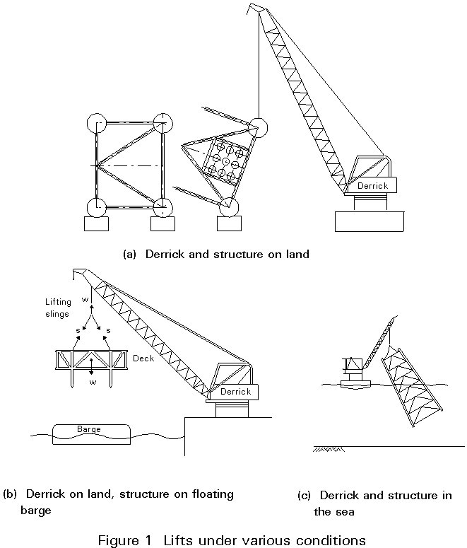
Lifting forces are functions of the weight of the structural component being lifted, the number and location of lifting eyes used for the lift, the angle between each sling and the vertical axis and the conditions under which the lift is performed (Figure 1). All members and connections of a lifted component must be designed for the forces resulting from static equilibrium of the lifted weight and the sling tensions. Moreover, API-RP2A recommends that in order to compensate for any side movements, lifting eyes and the connections to the supporting structural members should be designed for the combined action of the static sling load and a horizontal force equal to 5% this load, applied perpendicular to the padeye at the centre of the pin hole. All these design forces are applied as static loads if the lifts are performed in the fabrication yard. If, however, the lifting derrick or the structure to be lifted is on a floating vessel, then dynamic load factors should be applied to the static lifting forces. In particular, for lifts made offshore API-RP2A recommends two minimum values of dynamic load factors: 2,0 and 1,35. The first is for designing the padeyes as well as all members and their end connections framing the joint where the padeye is attached, while the second is for all other members transmitting lifting forces. For loadout at sheltered locations, the corresponding minimum load factors for the two groups of structural components become, according to API-RP2A, 1,5 and 1,15, respectively.
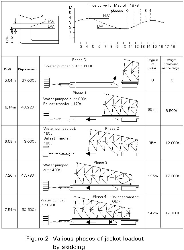
These are forces generated when the jacket is loaded from the fabrication yard onto the barge. If the loadout is carried out by direct lift, then, unless the lifting arrangement is different from that to be used for installation, lifting forces need not be computed, because lifting in the open sea creates a more severe loading condition which requires higher dynamic load factors. If loadout is done by skidding the structure onto the barge, a number of static loading conditions must be considered, with the jacket supported on its side. Such loading conditions arise from the different positions of the jacket during the loadout phases, (as shown in Figure 2), from movement of the barge due to tidal fluctuations, marine traffic or change of draft, and from possible support settlements. Since movement of the jacket is slow, all loading conditions can be taken as static. Typical values of friction coefficients for calculation of skidding forces are the following:
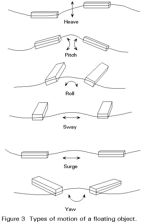
These forces are generated when platform components (jacket, deck) are transported offshore on barges or self-floating. They depend upon the weight, geometry and support conditions of the structure (by barge or by buoyancy) and also on the environmental conditions (waves, winds and currents) that are encountered during transportation. The types of motion that a floating structure may experience are shown schematically in Figure 3.
In order to minimize the associated risks and secure safe transport from the fabrication yard to the platform site, it is important to plan the operation carefully by considering, according to API-RP2A [3], the following:
Transportation forces are generated by the motion of the tow, i.e. the structure and supporting barge. They are determined from the design winds, waves and currents. If the structure is self-floating, the loads can be calculated directly. According to API-RP2A [3], towing analyses must be based on the results of model basin tests or appropriate analytical methods and must consider wind and wave directions parallel, perpendicular and at 45° to the tow axis. Inertial loads may be computed from a rigid body analysis of the tow by combining roll and pitch with heave motions, when the size of the tow, magnitude of the sea state and experience make such assumptions reasonable. For open sea conditions, the following may be considered as typical design values:
Single - amplitude roll: 20°
Single - amplitude pitch: 10°
Period of roll or pitch: 10 second
Heave acceleration: 0,2 g
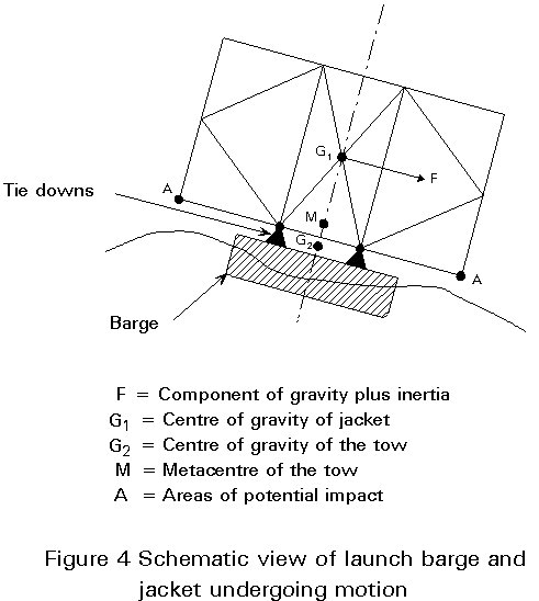
When transporting a large jacket by barge, stability against capsizing is a primary design consideration because of the high centre of gravity of the jacket. Moreover, the relative stiffness of jacket and barge may need to be taken into account together with the wave slamming forces that could result during a heavy roll motion of the tow (Figure 4) when structural analyses are carried out for designing the tie-down braces and the jacket members affected by the induced loads. Special computer programs are available to compute the transportation loads in the structure-barge system and the resulting stresses for any specified environmental condition.
These forces are generated during the launch of a jacket from the barge into the sea and during the subsequent upending into its proper vertical position to rest on the seabed. A schematic view of these operations can be seen in Figure 5.
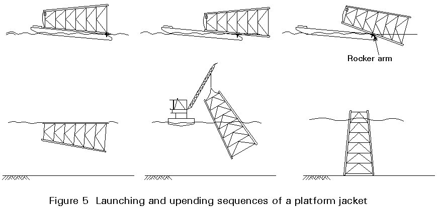
There are five stages in a launch-upending operation:
a. Jacket slides along the skid beams
b. Jacket rotates on the rocker arms
c. Jacket rotates and slides simultaneously
d. Jacket detaches completely and comes to its floating equilibrium position
e. Jacket is upended by a combination of controlled flooding and simultaneous lifting by a derrick barge.
The loads, static as well as dynamic, induced during each of these stages and the force required to set the jacket into motion can be evaluated by appropriate analyses, which also consider the action of wind, waves and currents expected during the operation.
To start the launch, the barge must be ballasted to an appropriate draft and trim angle and subsequently the jacket must be pulled towards the stern by a winch. Sliding of the jacket starts as soon as the downward force (gravity component and winch pull) exceeds the friction force. As the jacket slides, its weight is supported on the two legs that are part of the launch trusses. The support length keeps decreasing and reaches a minimum, equal to the length of the rocker beams, when rotation starts. It is generally at this instant that the most severe launching forces develop as reactions to the weight of the jacket. During stages (d) and (e), variable hydrostatic forces arise which have to be considered at all members affected. Buoyancy calculations are required for every stage of the operation to ensure fully controlled, stable motion. Computer programs are available to perform the stress analyses required for launching and upending and also to portray the whole operation graphically.
According to the DNV rules [2], accidental loads are loads, ill-defined with respect to intensity and frequency, which may occur as a result of accident or exceptional circumstances. Accidental loads are also specified as a separate category in the NPD regulations [4], but not in API-RP2A [3], BS6235 [1] or the DOE-OG rules [5]. Examples of accidental loads are loads due to collision with vessels, fire or explosion, dropped objects, and unintended flooding of bouyancy tanks. Special measures are normally taken to reduce the risk from accidental loads. For example, protection of wellheads or other critical equipment from a dropped object can be provided by specially designed, impact resistant covers. According to the NPD regulations [4], an accidental load can be disregarded if its annual probability of occurrence is less than 10-4. This number is meant as an order of magnitude estimate and is extremely difficult to compute. Earthquakes are treated as an environmental load in offshore structure design.
The load combinations used for designing fixed offshore structures depend upon the design method used, i.e. whether limit state or allowable stress design is employed. The load combinations recommended for use with allowable stress procedures are:
a. Dead loads plus operating environmental loads plus maximum live loads, appropriate to normal operations of the platform.
b. Dead loads plus operating environmental loads plus minimum live loads, appropriate to normal operations of the platform.
c. Dead loads plus extreme (design) environmental loads plus maximum live loads, appropriate for combining with extreme conditions.
d. Dead loads plus extreme (design) environmental loads plus minimum live loads, appropriate for combining with extreme conditions.
Moreover, environmental loads, with the exception of earthquake loads, should be combined in a manner consistent with their joint probability of occurrence during the loading condition considered. Earthquake loads, if applicable, are to be imposed as a separate environmental load, i.e., not to be combined with waves, wind, etc. Operating environmental conditions are defined as representative of severe but not necessarily limiting conditions that, if exceeded, would require cessation of platform operations.
The DNV rules [2] permit allowable stress design but recommend the semi-probabilistic limit state design method, which the NPD rules also require [4]. BS6235 permits both methods but the design equations it gives are for the allowable stress method [1]. API-RP2A is very specific in recommending not to apply limit state methods. According to the DNV and the NPD rules for limit state design, four limit states must be checked:
For this limit state the following two loading combinations must be used:
Ordinary: 1,3 P + 1,3 L + 1,0 D + 0,7 E, and
Extreme : 1,0 P + 1,0 L + 1,0 D + 1,3 E
where P, L, D and E stand for Permanent (dead), Operating (live), Deformation (e.g., temperature, differential settlement) and Environmental loads respectively. For well controlled dead and live loads during fabrication and installation, the load factor 1,3 may be reduced to 1,2. Furthermore, for structures that are unmanned during storm conditions and which are not used for storage of oil and gas, the 1,3 load factor for environmental loads - except earthquakes - may be reduced to 1,15.
All load factors are to be taken as 1,0.
All load factors are to be taken as 1,0.
All load factors are to be taken as 1,0.
The so-called characteristic values of the loads used in the above combinations and limit states are summarized in Table 2, taken from the NPD rules.
[1] BS6235, "Code of Practice for Fixed Offshore Structures", British Standards Institution, London, 1982.
[2] "Rules for the Design, Construction and Inspection of Offshore Structures", Det Norske Veritas (DNV), Oslo, 1977 (with corrections 1982).
[3] API-RP2A, "Recommended Practice for Planning, Designing and Constructing Fixed Offshore Platforms", American Petroleum Institute, Washington, D.C., 18th ed., 1989.
[4] "Regulation for Structural Design of Load-bearing Structures Intended for Exploitation of Petroleum Resources", Norwegian Petroleum Directorate (NPD), 1985.
[5] DOE-OG, "Offshore Installation: Guidance on Design and Construction", U.K. Department of Energy, London 1985.
Table 1 Minimum design live load specification
|
Loads to be taken into account (kN/m2) |
For portions of the structure |
For the structure as a whole |
|
|
Zone considered |
Flooring and joists |
Other components |
(3) |
|
Process zone (around wells and large-scale machines) |
5 (1) |
5 (1) |
2.5 |
|
Drilling zone |
5 (1) |
5 (1) |
2.5 |
|
Catwalks and walking platforms (except emergency exits) |
3 |
2.5 |
1 |
|
Stairways (except emergency exits) |
4 |
3 |
0 |
|
Module roofing |
2 |
1.5 |
1 |
|
Emergency exits |
5 |
5 |
0 |
|
STORAGE |
|
|
|
|
Storage floors - heavy Storage floors - light |
18 9 |
12 6 |
8 (2) 4 (2) |
|
Delivery zone |
10 |
10 |
5 |
|
Non-attributed area |
6 |
4 |
3 |
(1) Accumulated with a point load equal to the weight of the heaviest part likely to be removed, with a minimum value of 5 kN. Point loads are assumed as being applied to a 0,3m ´ 0,3m surface.
(2) Applied on the entirety of the flooring surface (including traffic).
(3) This column gives the loads to be taken into account for the structure's overall calculation. These values are the input for the computer runs.
Table 2 Characteristic Loads according to NPD [4]
|
LOAD TYPE |
LIMIT STATES FOR TEMPORARY PHASES |
LIMIT STATES FOR NORMAL OPERATIONS |
||||||||
|
Serviceability |
Fatigue |
Ultimate |
Progressive Collapse |
Serviceability |
Fatigue |
Ultimate |
Progressive Collapse |
|||
|
Abnormal effects |
Damage condition |
Abnormal effects |
Damage condition |
|||||||
|
DEAD |
EXPECTED VALUE |
|||||||||
|
LIVE |
SPECIFIED VALUE |
|||||||||
|
DEFORMATION |
EXPECTED EXTREME VALUE |
|||||||||
|
ENVIRONMENTAL |
Dependent on operational requirements |
Expected load history |
Value dependent on measures taken |
Dependent on operational requirements |
Expected load history |
Annual exceedance probability 10-2 |
Annual exceedance probability 10-4 |
Annual exceedance probability 10-2 |
||
|
ACCIDENTAL |
NOT APPLICABLE |
Dependent on operational requirements |
NOT APPLICABLE |
Annual exceedance probability 10-4 |
NOT APPLICABLE |
|||||