ESDEP WG 7
ELEMENTS
To derive the equations for the buckling loads of built-up columns and to present the design methods used in Eurocode 3 [1].
Lectures 6: Applied Stability
Lectures 7.5: Columns
Worked Example 7.6: Built-Up Columns
This lecture is divided into two main parts; the first part concentrates on the influence of shear deformations on the elastic critical loads and on the slenderness of columns (this effect is crucial for built-up columns and secondary for solid columns - rolled or welded shapes); the second part deals with the design approach adopted in Eurocode 3 [1] which is related to experimental behaviour.
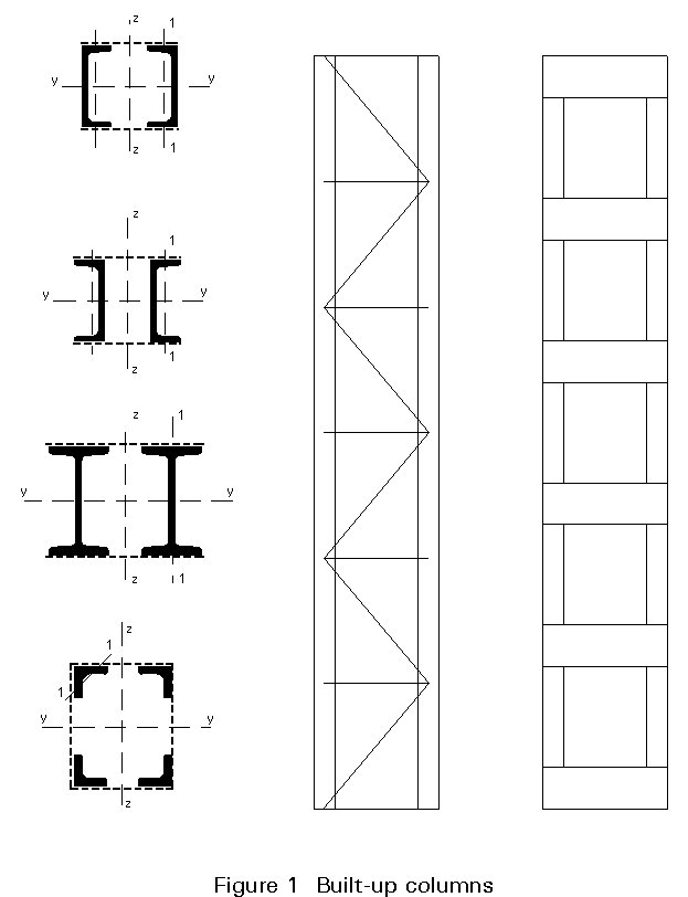
Built-up columns are widely used in steel construction especially when the effective lengths are great and the compression forces light. They are composed of two or more parallel main components interconnected by lacing or batten plates (Figures 1 and 2). The greater the distance between the chord axes, the greater is the moment of inertia of the built-up cross section; the increase in stiffness, however, is counterbalanced by the increased weight and cost of the connection of members.
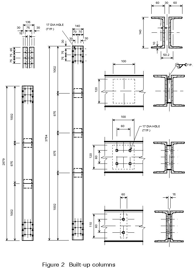
It should be noted that built-up columns (especially battened built-up columns) are more flexible than solid columns with the same moment of inertia; this must be taken into account in the design.
In order to derive the carrying capacity of steel built-up columns, the following must be studied:
This section discusses the effect of shear deformation on the elastic critical column load.
The simple case of a pin-ended column, shown in Figure 3, is considered; for M, N, V, x and y, as defined in this Figure, the following relationships hold:
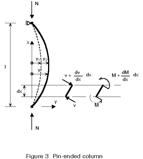
M = N y, ![]() (2.1)
(2.1)
The total lateral deflection y of the centreline is the result of two components:
y = y1 + y2 (2.2)
the bending moment M gives rise to the deflection y1, and the shearing force V to the additional deflection y2.
According to elastic theory the curvature due to the bending moment M is as follows:
![]() (2.3)
(2.3)
where
E is the modulus of elasticity or Young's modulus.
I is the moment of inertia of the cross-section.
The slope due to the shearing force V is as follows:
![]() (2.4)
(2.4)
where
A is the cross-sectional area.
G is the modulus of rigidity or shear modulus.
b
is the shape factor of the column cross-section (b =1,11 for solid circular cross-sections; b = 1,2 for rectangular cross-sections).The curvature due to the effect of the shearing force V is as follows:
![]() (2.5)
(2.5)
The total curvature of the buckling curve is due both to the bending moment, Equation (2.3), and to the shearing force, Equation (2.5):
![]() (2.6)
(2.6)
It is possible to rearrange Equation (2.6) in the form:
![]() (2.7)
(2.7)
Adopting the same procedure as in the Euler case, the critical load is defined by the equation:
![]() (2.8)
(2.8)
Solving for N, the following expression for the elastic critical load Ncr,id is obtained:
 (2.9)
(2.9)
where:
Ncr = ![]() is the Euler buckling load obtained disregarding the deformations due to shearing force
is the Euler buckling load obtained disregarding the deformations due to shearing force
Sv = ![]() is the shear stiffness of the column.
is the shear stiffness of the column.
Obviously Ncr,id < Ncr ; the greater the ratio Ncr / Sv, the smaller the ratio Ncr,id/ Ncr < 1. The ratio Ncr,id / Ncr obtained from Equation (2.9) is plotted, in Figure 4, as a function of the ratio Ncr / Sv.
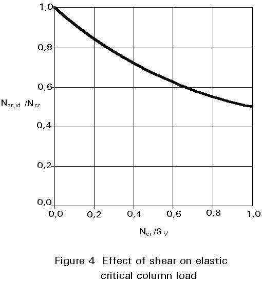
For solid rolled cross-sections the shear stiffness Sv is much greater than N. The difference between Ncr,id and Ncr is very small therefore, and can be disregarded for design purposes.
However, as will be shown below, the shear stiffness Sv, of built-up columns, is much smaller than it is for solid shapes; in this case, therefore, the influence of the shearing forces on the reduction of the critical load is very significant.
In order to compare the shear stiffness Sv to the Euler buckling loads of solid columns Ncr, consider as an example a HE200A column buckling in the plane of the web.
The shear stiffness Sv is as follows:
Sv = ![]()
E = 200 kNmm-2
n
= 0,3Aw = the area of the web = 6,5 x 170 = 1105 mm2
The Euler buckling load Ncr is:
Ncr = ![]()
where:
A is the cross-sectional area = 5380 mm2.
l
is the slenderness of the column.In Table 1 the critical buckling loads Ncr,id, the Euler buckling loads Ncr, and the ratios Ncr / Sv are given as functions of the slenderness; it clearly shows that in the case of solid cross-sections, Ncr is always far smaller than Sv; therefore, for technical purposes, it is possible to disregard the influence of the shear deformations on the elastic buckling loads Ncr,id.
In laced columns the elastic extension of the diagonals and the horizontals must be considered in order to derive the shear stiffness Sv; the elongation of the chords (the main components) should not be taken into account, because they are already considered in the global flexural stiffness E I of the built-up column.
With an N-shape arrangement of lacing, as shown in Figure 5, the elongations of one diagonal and of one horizontal are taken into account in order to derive Sv:
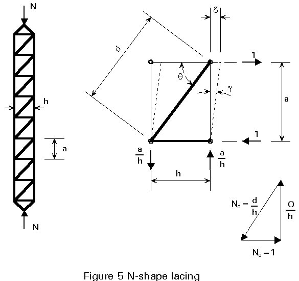
1/Sv = d/a = g (3.1)
where d is the lateral displacement due to the unit shearing force.
The total displacement d is the result of two components: d1 is the contribution from the elongation of the diagonal; d2 is the contribution from the shortening of the horizontal. From virtual work theory:
![]()
Thus, for one plane of lacing:
![]() (3.2)
(3.2)
With an A shape arrangement of lacing, as shown in Figure 6:
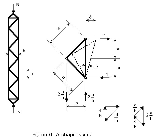
![]()
Therefore:
![]() (3.3)
(3.3)
The cross-bracings, shown in Figure 7, have the same shear stiffness, because the horizontals do not take part in the transmission of the shearing force:
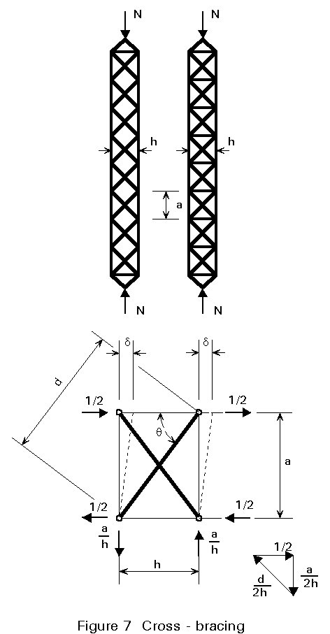
![]()
and the shear stiffness is:
![]() (3.4)
(3.4)
For battened built-up columns, as shown in Figure 8, the flexural deformations both of the chords and of the battens must be considered in order to derive the shear stiffness Sv; as is the case for laced built-up columns, the extensions of the main chords are not considered because their contributions appear in the global flexural stiffness E I.
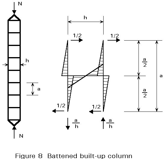
Adopting the virtual work method, the displacement d due to unit shearing force is obtained:
and the shear stiffness is:
![]() (3.5)
(3.5)
where Ic is the in-plane second moment of area of one chord.
Ib is the in-plane second moment of area of one batten.
The above formula may be refined by taking into account the deformations due to the shearing force in the battens.
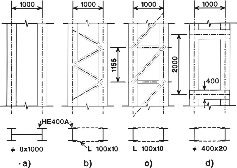
Table 2 gives a comparison of the shear stiffness Sv for a solid column and three different built-up columns; the global dimensions of the cross-sections and the weights of steel per unit length are kept constant.
The solid column (a) is made up of two HE400A shapes each welded to a common plate 8mm thick x 1000mm wide.
Built-up columns (b) and (c) are laced: the chords are HE400A shapes and there are two planes of lacing with 100 ´ 10 equal angles.
Built-up column (d) is with batten plates: the same shape HE400A as above is adopted for the chords; the batten plates, which have rectangular cross-section 400 ´ 20mm, are on two planes.
Whereas the steel employed in the web and in the connecting members has almost the same weight in the four columns, Table 2 shows that the shear stiffness Sv has a wide range of variation.
For design purposes the elastic critical loads of built-up columns can be obtained from Equation (2.9): that is, it is possible to assume a continuous distribution of the shear stiffness Sv if the number of panels is greater than or equal to six; if not, more complex analysis, with methods suitable for frames, has to be performed (for further reading on this topic see (1, 2, and 3).
By introducing formulae for the shear stiffness Sv (3.2, 3.3, 3.4 and 3.5) in Equation (2.9), it is easy to derive, for the various types of lacings and battens, specific formulae for the elastic critical loads Ncr,id and, as a consequence, for the effective length of built-up columns; formulae of this type are widely adopted in the European codes and standards for steel construction.
The details of the analytical procedure are now outlined.
When the lacing is N shaped (as shown in Figure 5), the expression for the shear stiffness Sv (3.2) is substituted in Equation (2.9), where:
Ncr = p2 E I / l2 is the Euler critical load, as for a solid column.
I = 2 Ic + Ac h2, is the moment of inertia of the built-up cross-section.
Ac is the cross-sectional area of the chords.
Ic is the relevant moment of inertia of the chords.
Substitution gives the following:
 (4.1)
(4.1)
By introducing the slenderness l for the column without shear deformations, such that:
l
2 = 1/ r2 = 2 Ac l2 /Ithe elastic critical stress scr,id, for the built-up column becomes:
 (4.2)
(4.2)
where:
 (4.3)
(4.3)
is the equivalent slenderness of the built-up column.
Following the same procedure, when simple A bracing (Figure 6) is adopted, the equivalent slenderness of the column is:
 (4.4)
(4.4)
For cross-bracing (Figure 7):
 (4.5)
(4.5)
Finally, for battened built-up columns (Figure 8), the equivalent slenderness is:
 (4.6)
(4.6)
If the batten plates are very stiff, their flexural deformations may be disregarded and it is possible to put:
![]() , in Equation (4.6).
, in Equation (4.6).
In this case the equivalent slenderness of battened built-up columns becomes:
leq = Ö{l2 + p2Aca2 /(12Ic)} = Ö{l2 + p2l12 /12} (4.7)
where l1 is the local slenderness of the chords between the centrelines of the batten plates.
The experimental behaviour of a steel built-up column (with batten plates) [2] in a compression test up to collapse, is summarised in Figure 9.
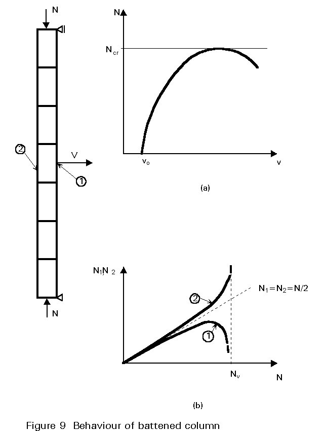
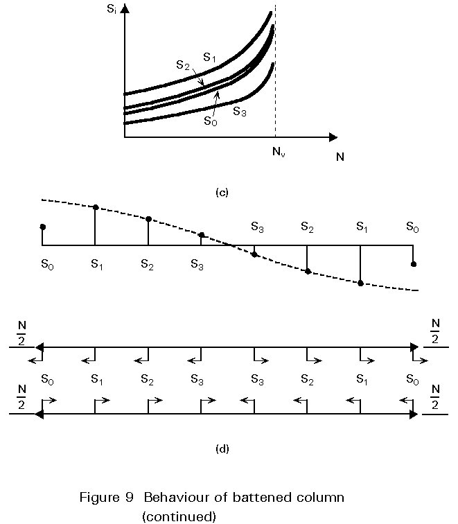
Due to the initial geometrical imperfections and residual stresses, the lateral displacements increase with the applied load more and more rapidly up to the bearing capacity Ncr of the column; the presence of lateral displacements explains why one chord is more compressed than the other, which tends to unload after it has reached maximum compression.
In the batten plate at the end, the framing effect is smaller than in the next internal one, because of the presence of only half a field.
The maximum carrying capacity of the built-up column is reached when one of the following possibilities occurs:
The main features of the experimental behaviour of a built-up compression member summarised above may be represented by a simple elastic column with equivalent initial geometrical imperfections and shear flexibility (Figure 10).
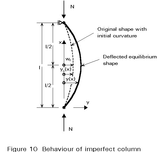
The design philosophy of Eurocode 3 [1] is based on this simple model: it is assumed that in the initial unloaded state the column is not perfectly straight and that the initial deflection y (x) is given by a sine curve for a pin-ended member:
yo (x) = wo sin (p x / l) (5.1)
where
wo is the equivalent geometrical out of straightness at mid-span (wo = 0,002l = l / 500);
l is the length of the pin-ended column.
When the design axial load N is applied to the built-up column the initial geometrical imperfection is then amplified elastically; the lateral displacements in the equivalent state are:
![]() sin (p x / l) (5.2)
sin (p x / l) (5.2)
where, in Equation (5.2), Ncr,id is the elastic critical load of the built-up column as given in Section 4.
At mid-span of the built-up column, the axial force is N and the bending moment M equals:
![]() (5.3)
(5.3)
The axial force Nf in the most loaded chord is:
 (5.4)
(5.4)
The buckling resistance of the chords NRd must be greater than Nf:
NRd ³ Nf (5.5)
In laced built-up columns the effective length of the chords is taken equal to the system length between lacing connections; in battened built-up columns (for the sake of simplicity and disregarding any possible end restraint) the effective length of the chords is taken equal to the distance between the centre lines of the battens.
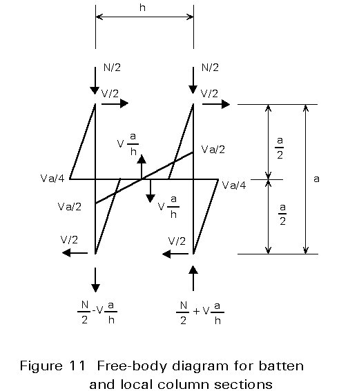
The shearing force V at the ends of a built-up column is given by:
![]() (5.6)
(5.6)
The forces in the lacing members and in the chords adjacent to the ends are derived from the shearing force V and from the axial force N.
The battens, their connections to the chords, and the chords themselves are checked for the moments and forces due to the shearing force V and the axial force N as shown in Figure 11.
The design philosophy of Eurocode 3 [1] may be summarized in the following six steps:
[1] Eurocode 3: "Design of Steel Structures": ENV 1993-1-1: Part 1.1: General rules and rules for buildings, CEN, 1992.
[2] Ballio, G. & Mazzolani, F. M., "Theory and Design of Steel Structures", Chapmann and Hall, New York, 1983.
Table 1 Example of the influence of shear flexibility on stability
|
l |
80 | 90 | 100 | 110 | 120 | 130 | 140 |
|
Ncr,id (MN) |
1,63 |
1,29 |
1,05 |
0,869 |
0,731 |
0,624 |
0,538 |
|
Ncr (MN) |
1,66 |
1,31 |
1,06 |
0,878 |
0,738 |
0,628 |
0,542 |
|
Ncr / Sv |
0,020 |
0,015 |
0,12 |
0,010 |
0,009 |
0,007 |
0,006 |
Table 2 Examples of shear stiffnesses for solid, laced and battened columns
|
|
|
a) Shear stiffness Sv = E = 20 MN cm-2 u = 0,3 Aw = 100 x 0,8 = 80 cm2 Sv = Volume and mass of steel V = 0,8 x 100 x 100 = 8000 cm3 m-1 W = Ys V = 0,00785 x 8000 = 63 kg m-1 |
Table 2 - Continued
|
b) Shear Stiffness Sv = L 100 ´ 10 Ad = 19,2 cm2 h = 100 cm a = 115,5 / 2 = 57,75 cm d = 2 a = 115,5 cm Sv = Volume and mass of steel V = 19,2 x 115,5 x 4 / 1,155 = 7680 cm3 m-1 W = 0,00785 x 7680 = 60 kg m-1 |
|
c) Shear Stiffness Sv = Ad = Ao = 19,2 cm2 h = 100 cm a = 115,5 cm d = (a2 + h2)0,5 = 152,8 cm Sv = Volume and mass of steel V = 19,2 x (100 + 152,8) x 2 / 1,155 = 8405 cm3 m-1 W = 0,00785 x 8405 = 66 kg m-1 |
Table 2 - Continued
|
d) Shear Stiffness Sv = Ic = 8564 cm4 H E 400 A Ib = 403 x 2 x 2 / 12 = 21333 cm4 a = 200 cm h = 100 cm Sv = Volume and mass of steel V = 2 x 40 x 100 x 2/2 = 8000 cm3 W = 0,00785 * 8000 = 63 kg m-1 |
||
|
a) Web 8 ´ 1000 b) Lacing L 100 ´ 10 c) Lacing L 100 ´ 10 d) Batten plates 400 ´ 20 |
Shear Stiffness Sv (MN) 615 288 194 73 |
Mass of Steel W (kg m-1) 63 60 66 63 |