ESDEP WG 13
TUBULAR STRUCTURES
To gain an understanding of the structural application of steel hollow sections. To describe where and how to use them.
Lecture 1A.2: Steelmaking and Steel Products
Lectures 2.3: Engineering Properties of Steels
Lectures 3.1: General Fabrication of Steel Structures
Lecture 11.1.2: Introduction to Connection Design
Lectures 12.4: Fatigue Behaviour of Hollow Section Joints
Lecture 13.2: The Behaviour and Design of Welded Connections between Circular Hollow Sections under Predominantly Static Loading
Lecture 13.3: The Behaviour and Design of Welded Connections between Rectangular Hollow Sections under Predominantly Static Loading
Structural hollow sections, circular (CHS) and rectangular (RHS), have excellent properties for resisting static loads, not only with regard to buckling, bi-axial bending and torsion, but also in the overall design of members. They can offer economic advantages in comparison with other sections. Good design of structures using hollow sections makes use of their specific properties right from the beginning.
The notation in Eurocode 3, Annex K [1], has been adopted.
Mankind has learnt the application of hollow tubular members as structural elements from nature. Many examples in nature show not only the use of a hollow cylinder to transmit a fluid, but also the excellent properties of the tubular shape with regard to loading in compression, torsion and bending in all directions. These advantages were quickly understood by our ancestors, when in their hands the bamboo pole became a light building component as well as a pipe for the supply of drinking water or for irrigation.
During the development of steel production and the manufacture of classical hot-rolled open sections such as I-, L- and U-profiles, the first methods for the fabrication of tubes or circular hollow sections were developed in the nineteenth century. The production of rectangular hollow sections was not started, however, until 1952 (by Stewarts & Lloyds in the United Kingdom).
Circular shaped tubes are made either from a solid lump of steel, producing seamless tubes, or from a flat strip, giving welded tubes. There is no fundamental difference between the production process for a circular section tube intended for use as a pipe and that for a similar hollow section intended for a structural use.
The so-called "form" tubes - square, rectangular, hexagonal or octagonal - are obtained by deforming, either hot or cold, a round tube as a blank. The circular blank tube is passed through forming roll cages working continuously and outwards only. This process gives the blank, usually after passing over several sets of rolls, the required shape, which is normally square and rectangular.
The selection of a particular profile in a steel structure is governed by many factors. It involves a comparison of the pros and cons with regard to mechanical properties, unit material costs and the costs of fabrication, erection and maintenance. The experiences of architects, designers and fabricators also affect the choice. It is therefore very important that those involved should understand the behaviour of hollow sections and their connections.
Hollow sections as steel profiles are not only in competition with concrete, but also they may substitute for other steel profiles due to their superiority with regard to strength and stability. The mechanical and geometrical properties of the hollow section indicates under which loadings a saving in material can be obtained.
The material grades in which structural hollow sections are delivered according to Eurocode 3 [1] are given in Table 1.
In cold-finished sections, the increase in yield stress due to cold forming can be taken into account. Table 2 shows the recommendations and formulae for applying this increment.
To allow welding in the region of the corners of cold finished rectangular hollow sections, the requirements given in Table 3 should be met.
The selection of hollow sections depends on their geometrical properties and thus on the member resistances for particular loading cases. Tolerances are in general lower than for open sections.
The design strength of a member under a tensile loading depends on the cross-sectional area and the design yield stress, and is independent of the sectional shape. In principle, there is no advantage or disadvantage in using hollow sections from the point of view of the amount of material required.
For centrally loaded members in compression, the critical buckling load depends on the slenderness l and the section shape.
The slenderness l depends on the buckling length l and the radius of gyration r.
l = l/r
The radius of gyration of hollow sections, (in relation to the member mass) is generally much higher than for that about the weak axis of open sections. For a given load this difference results in a lower slenderness for hollow sections and thus a lower mass when compared with open sections.
The buckling behaviour is influenced by initial eccentricities, straightness and geometrical tolerances, residual stresses, inhomogeneity of the steel and the stress-strain relationship.
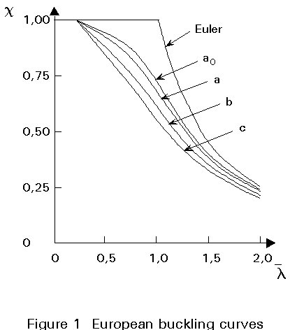
Based on an extensive investigation by the European Convention for Construction Steelwork, "European buckling curves" (Figure 1) are established for various steel sections including hollow sections. They are incorporated in Eurocode 3 [1].
The reduction factor c shown in Figure 1 is the ratio of the design buckling resistance Nb,Rd to the axial plastic resistance Npl,Rd:
c = ![]()
where
fb,Rd = ![]() (the design buckling stress)
(the design buckling stress)
fyd = fy / gM (the design yield strength)
g
M is the partial safety factorThe non-dimensional slenderness ![]() is determined by
is determined by ![]() =
l / lE
=
l / lE
where lE = p ![]() (Euler slenderness).
(Euler slenderness).
The buckling curves for the hollow sections are classified according to Table 4.
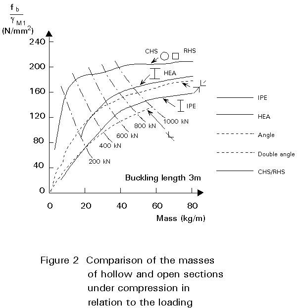
Most open sections fall under curves "b" and "c". Consequently, for the case of buckling, the use of hot-formed hollow sections generally provides a considerable saving in mass.
Figure 2 shows a comparison between the required mass of open and hollow sections for a given load.
The overall buckling behaviour of hollow sections improves with increasing diameter or width-to-wall thickness ratio. However, this improvement is limited by local buckling. To prevent local buckling, d/t, or b/t limits are given in Eurocode 3 for plastic as well as elastic design (Table 7).
In the case of thin-walled sections, interaction between buckling and local buckling should be considered.
In addition to the improved buckling behaviour due to high radius of gyration and the enhanced design buckling curve, hollow sections can offer other advantages in lattice girders. Due to the torsional and bending stiffness of the members in combination with certain joint fixity, the effective buckling length of compression members can be reduced. Eurocode 3 [1] recommends the effective buckling lengths for hollow sections in lattice girders as shown in Table 5.
Laterally unsupported bottom chords of lattice girders have a reduced buckling length due to the improved torsional and bending stiffness of the tubular members. These factors make the use of hollow sections in girders even more favourable.
Hollow sections, especially CHS have the most effective cross-section for resisting torsional moments, because the material is uniformly distributed about the polar axis. A comparison of open and hollow sections of nearly identical mass in Table 6 shows that the torsional constant of hollow sections is 200 to 300 times larger than that of open sections.
In general, the UB and UC sections are more economical under bending (Imax larger than for hollow sections). Only in those cases in which the design stress in open sections is largely reduced by lateral buckling, can hollow sections offer an advantage. It can be shown by calculations that for circular hollow sections and for rectangular hollow sections with b/h >0,25, which are normally used, lateral instability is not critical.
Hollow sections used for elements subjected to bending can be more economically calculated using plastic design. For the use of compact sections in plastic design, the limiting d/t or b/t values are given in Eurocode 3 (see Table 7).
The fatigue behaviour of hollow section joints is influenced largely by the geometrical stress or strain concentration factor (SCF or SNCF).
A structure made of hollow sections should be designed and detailed so that the SCF or SNCF is low. In this way, economical design of hollow section joints is possible even under fatigue conditions, particularly when assessed in terms of low load coefficients for wind and wave, reduced mass and corrosion protection.
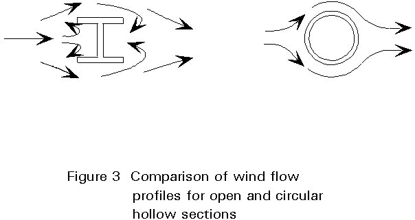
Hollow sections present a striking advantage for use in building structures exposed to fluid currents, i.e. air or water.
Their drag coefficients are much lower than those of ordinary sections with sharp edges (see Figure 3). The drag coefficients for wind loading on circular and rectangular hollow sections have been determined in the last twenty years by a series of tests [2].
Based on these tests, the following conclusions can be derived:
Re = V.D/u
where
V is the wind velocity;
D is the width of the cross section;
u is the kinematic viscosity.
The values are higher than those for hollow sections with rounded corners.
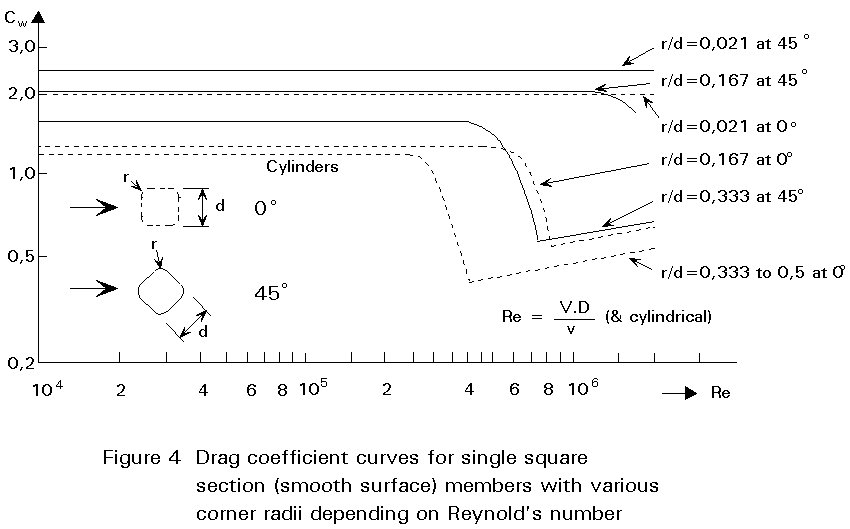
Further, Cw is governed by corner radius r, surface roughness k and wind direction angle a [2]. R/D for a circular cylinder is equal to 0,5.
Table 8 shows the drag coefficients of I-profiles and circular and rectangular hollow sections for simple calculations.
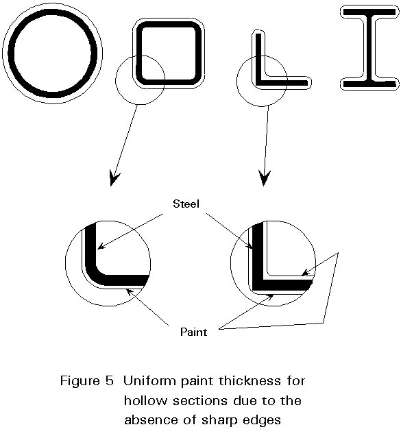
Structures made of hollow sections offer advantages with regard to corrosion protection. Hollow sections have rounded corners (Figure 5) which result in a better protection than open sections with sharp corners. This is especially true at joints in circular hollow sections where there is a smooth transition from one section to another. This better protection increases the protection period of coatings against corrosion.
Structures designed in hollow sections have a 20 to 50% smaller surface to be protected than comparable structures made using open sections. Many investigations have been carried out to assess the likelihood of internal corrosion. These investigations, carried out in various countries, show that internal corrosion does not occur in sealed hollow sections.
Even in hollow sections which are not perfectly sealed, internal corrosion is limited. If there is concern about condensation in an imperfectly sealed hollow section, a drainage hole can be made at a point where water cannot enter by gravity.
The internal void in hollow sections can be used to advantage in various ways, e.g. to increase the bearing resistance by filling with concrete, or to provide fire protection. In addition, the heating or ventilation system is sometimes incorporated into hollow section columns. The possibilities of using the internal space are briefly described below.
If the commonly available wall thicknesses are not sufficient to meet the required load-bearing resistance, the hollow section can be filled with concrete. For example, it may be preferable in buildings to have the same external dimensions for the columns on every floor. At the top floor, the smallest wall thickness can be chosen, and the wall thickness can be increased with increasing load for lower floors. If the hollow section with the largest available wall thickness is not sufficient for the ground floor, the hollow section can be filled with concrete to increase the load bearing resistance. A very important reason for using concrete-filled hollow sections is that the columns can be relatively slender. Design rules are given in Eurocode 4 [3].
One of the modern methods for fire protection of buildings is to use water-filled hollow section columns. The columns are interconnected with a water storage tank. Under fire conditions, the water circulates by convection, keeping the steel temperature below the critical value of 450°C. This system has economical advantage when applied to buildings with more than 8 storeys. If the water flow is adequate, the resulting fire resistance time is virtually unlimited.
In order to prevent freezing, potassium carbonate (K2CO3) is added to the water. Potassium nitrate is used as an inhibitor against corrosion.
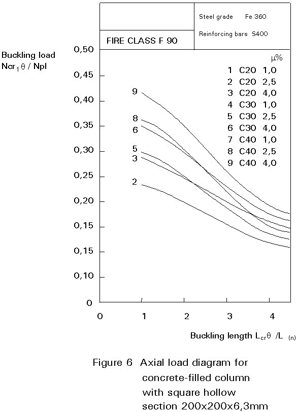
Concrete filling of hollow sections contributes not only to an increase in load- bearing resistance, but it also improves fire resistance duration. The extensive test projects carried out by CIDECT and ECSC have shown that reinforced concrete-filled hollow section columns without any external fire protection like plaster, asbestos and Vermiculite panels or intumescent paint, can attain a fire life of even 2 hours depending on the cross-section ratio of the steel and concrete, reinforcement percentage of the concrete and the applied load. Related calculation diagrams are available. Figure 6 shows an example.
The inner voids of hollow sections are sometimes used for air and water circulation for heating and ventilation of buildings. Many examples in offices and schools show the excellent combination of the strength function of hollow section columns with the integration of the heating or ventilation system. This system offers maximization of floor area through elimination of heat exchangers, a uniform provision of warmth and a combined protection against fire.
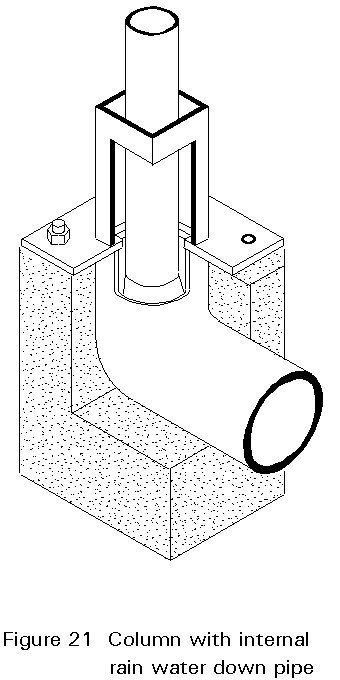
Sometimes hollow section chords of lattice girder bridges are used for conveying fluids (pipe bridge). The internal space can also be used for prestressing a hollow section. Sometimes in buildings the rain water downpipes go through the hollow section columns or in other cases electrical wiring is located in the columns.
A rational use of hollow sections leads in general to structures which are cleaner and more spacious. Hollow sections can provide slender aesthetic columns, with variable section properties but flush external dimensions. Due to their torsional rigidity, hollow sections have specific advantages in folded structures, V-type girders, etc.
The latticed construction, which is often made of hollow sections directly connected to one another without any stiffener or gusset plate, is often preferred by architects for structures with visible steel elements. However, it is difficult to express aesthetic features in economic comparisons. Sometimes hollow sections are used only because of aesthetic appeal, whilst at other times appearance is less important.
After the Second World War, riveted tubular structures had many joints with gusset plates. In the last thirty years the ratio of labour to material costs has increased rapidly in industrialized countries. For this reason, more attention should be paid to detailing simple joints.
As far as possible, joints should be designed without stiffeners or gusset plates. This, however, means that the designer should consider the joint strength of non-reinforced joints at the preliminary design stage.
Welding is the most important jointing technique for hollow section structures.
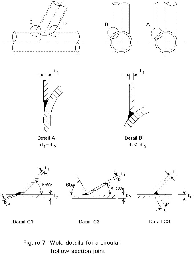
In general, the same welding procedures can be used as for open steel sections. Circular hollow sections can be joined with fillet welds if the diameter ratio between the sections to be connected does not exceed 0,33 and the weld gap does not exceed 3 mm. For larger ratios the weld can change smoothly from a fillet weld at the crown to a butt weld at the saddle, or a full butt weld over the entire perimeter can be used, see Figure 7.
Rectangular hollow sections can generally be joined with fillet welds. In the case of equal or near-equal widths, the side walls should be bevelled for a butt weld. When the angles at the toe are smaller than 60° , bevelling is required to obtain a good connection, see Figure 8.

To obtain sufficient deformation capacity, the welds should normally be designed on the basis of member strength, which generally results in throat thicknesses about equal to the thickness of the connected member.
According to Eurocode 3, Annex K [1], the throat thickness (a) of a fillet should normally satisfy the following conditions (lower values are currently the subject of discussion):
For S235, a ³ 0,92 t1
For S275, a ³ 0,96 t1
For S355, a ³ 1,11 t1
The end preparation should be as simple as possible. For example a gap joint or a 100% overlap joint is preferable compared to a joint with partially overlapping bracings (Figure 9).
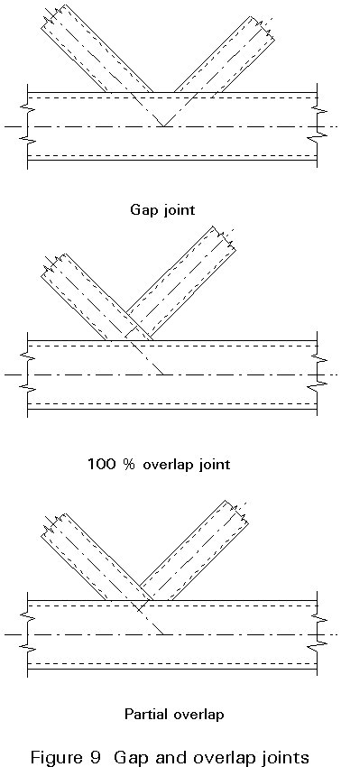
In the case of gap or 100% overlap joints, only one cut for each bracing end is necessary. For partial overlap joints one bracing has to be provided with a double or mitred cut. As far as possible, a square or rectangular hollow section should be used; in this way the ends can be made in a similar way as for open sections (plain cut).
Circular hollow sections may be chosen, especially when aerodynamic or fluid flow criteria are decisive in design. The ends of such sections must be shaped as 'saddles' to provide proper jointing. Shaping can be done by notching, milling, double end cutting, manual flame cutting or automatic flame cutting. Each of these methods has its advantages and disadvantages. The method selected depends on the equipment available to the fabricator, the type of structure and the specification.
For small sizes, the end can be prepared in many cases with some plane cuts, e.g. three cuts. This is a simple and economical method. For large sections an automatic flame cutting machine is preferable.
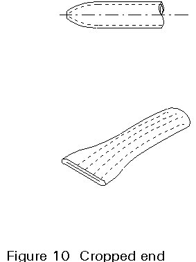
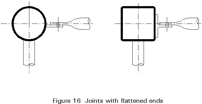
To avoid saddle profiling, the ends can be cropped or flattened. End cropping can be achieved in a guillotine cutter or for small sections with a notcher fitted with shearing tools. End cropping produces a linear contact at the ends (Figure 10). It is also possible to partly crop the ends in such a way that the distance between chord and bracing is smaller than about 3 mm which can be bridged by welding.
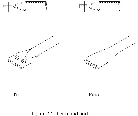
Full flattening (Figure 11) may be used for bolted connections. Experimental investigations show that hot finished hollow sections (up to 114 mm) can be cold flattened. The flattening can be symmetrical or non-symmetrical depending on the dye used.
Bending operations for hollow sections are carried out in the hot or cold condition. It should be considered that the wall thickness of the hollow section at the external radius of curvature can be decreased, whereas at the inner side of the curvature wall crippling may occur. Further, care should be taken that the ovality of a tube which can occur, is kept as small as possible.
The minimum inside radii recommended in the U.K. for rectangular hollow sections are given in Table 9. The bending radii for circular hollow sections of up to 159 mm external diameter are recommended by DIN 2916 [4]. The bending operation is commonly carried out by roller benders with three rollers.
The internal faces of hollow sections are, in principle, inaccessible, unless special measures are taken, such as the provision of hand holes, or unless the situation is a special one, i.e. when a connection is made at the open end. Usually, therefore, it is not possible to make direct bolted connections between hollow sections or between hollow sections and open ones, in the way normally done in steel construction.
Usually, drilled fittings, such as plates or angles, are welded to one or more hollow sections. The holes are used for bolts with or without prestressing. Bolted connections are preferred for assembly on site.
Examples are shown by the following constructions:
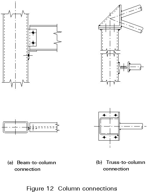
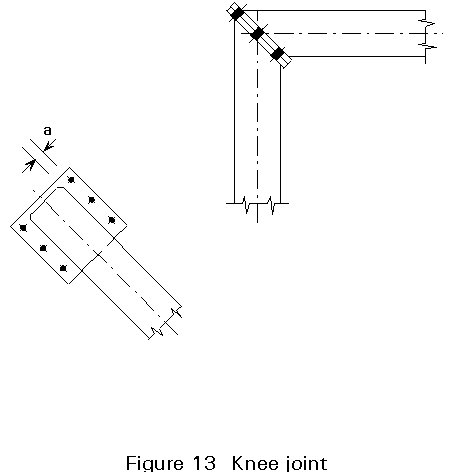
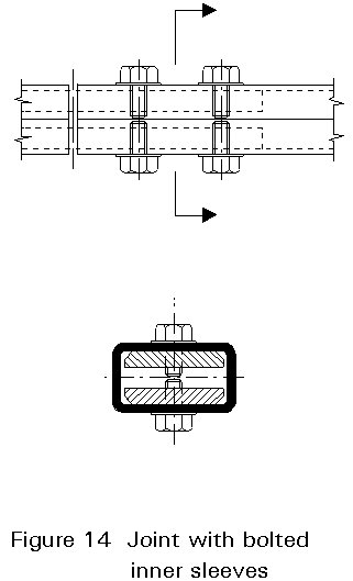
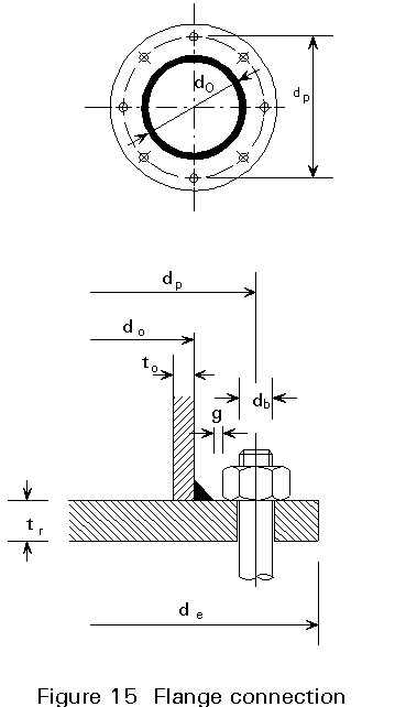
However, direct bolted connections can also be made using special blind bolts, screws and rivets, which can be secured from one side only of the parts being joined.
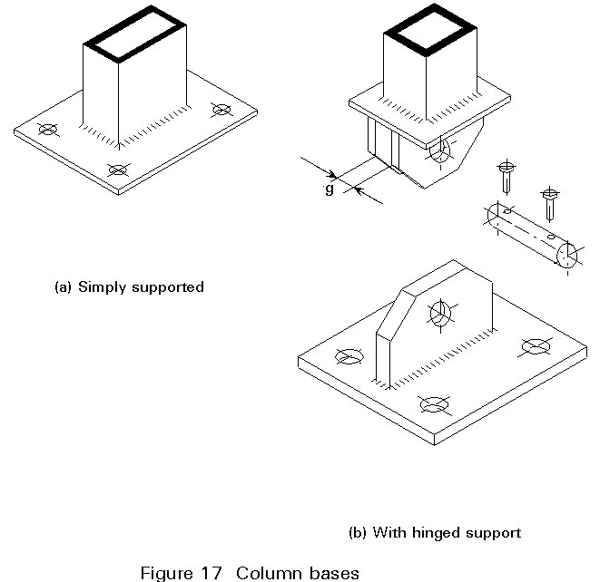
The magnitude of the end moment determines the structural arrangement that is called for. It is always worthwhile to examine first the simplest solution with a single end plate without any stiffener, even if a fairly thick plate is required.
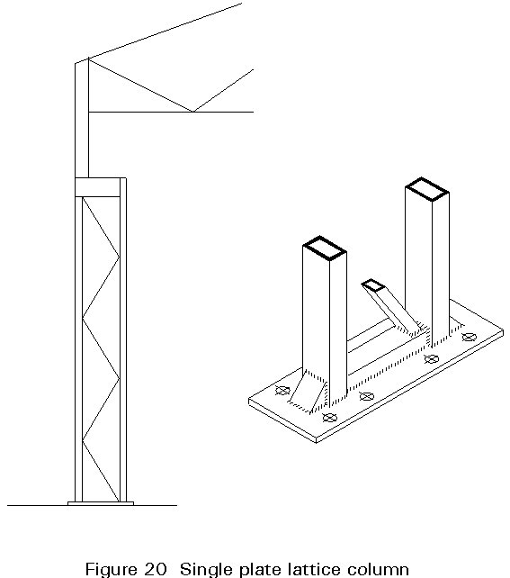
If this simple solution is not appropriate, more complex arrangements with stiffeners can be envisaged. Figure 20 shows the base of a single plate lattice column. Figure 21 shows an arrangement for connecting an internal rain water down pipe at the foot of a hollow section column. Precautions should be taken to protect the inside of the column against corrosion. The hollow section can be galvanised or a seal can be made at the head and the foot of the column.
Lattice girders are light and economical and they are fairly simple to design. Usually they comprise of an upper and a lower chord and a lattice consisting of bracing members (Figure 22). The chords may or may not be parallel.
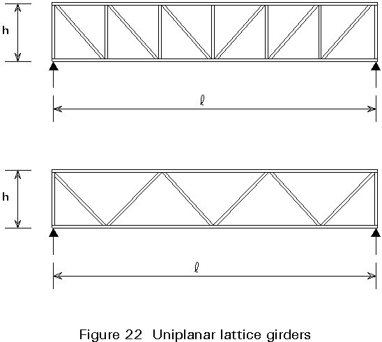
Lattice girders are characterised by the span "l", the depth "h", the lattice geometry, and the distance between the joints. The depth "h" is determined in relation to the span, loads, maximum deflection, etc. An increase in "h" reduces the loads in the chords, but increases the effective lengths of the bracings. The value of "h" is usually between l/10 and l/16. The joints are preferentially located at the load application points.
A lattice structure is usually designed so as to transmit the applied loads purely through axial loadings in the members. In hollow section girders, however, the chords are usually continuous and the bracings are welded onto the chords. Secondary bending moments are produced in both the members and the joints. It is nevertheless well accepted that, if the members and the joints are capable of redistributing these secondary moments in a plastic manner, the load analysis can be based on the pinned framework assumption that the framework is pinned.
Bending moments, on the other hand, must be considered when the axes of the members do not converge at a point of junction producing positive or negative eccentricity (see Figure 23).
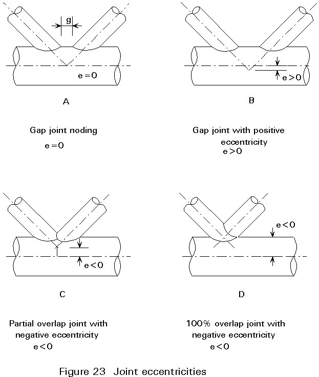
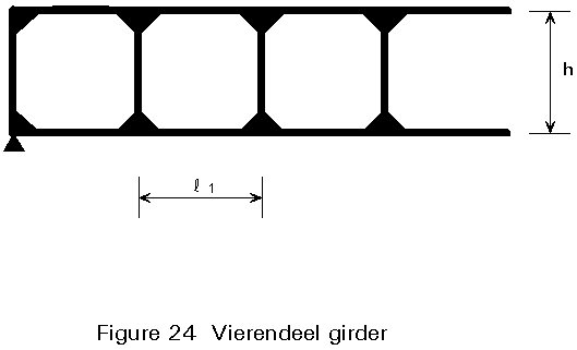
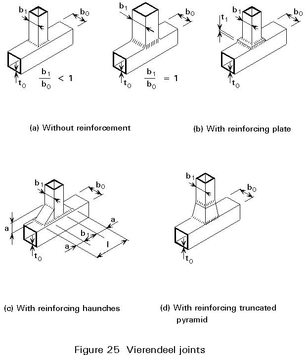
Figure 24 shows a vierendeel type girder where the sloping bracings are excluded. The design of the joints is based on the strength in bending of the components. Vierendeel joints with and without reinforcements are shown in Figure 25. They can be considered as T joints and design calculations are made accordingly.
Multiplanar trusses are, in general, represented by triangular and quadrangular girders. They are inherently stable, i.e. they require no external bracing of any kind and constitute autonomous load-bearing elements. These girders offer a spatial type of strength, which means they can withstand loads and bending moments from all directions. The depth of a girder is usually between l/18 and l/15 of the distance l between the supports.
The joint arrangement depends on the nature of the chord (circular, square, rectangular sections), the type of connection (bolted to gusset plates or welded, with or without flattening of bracing ends).
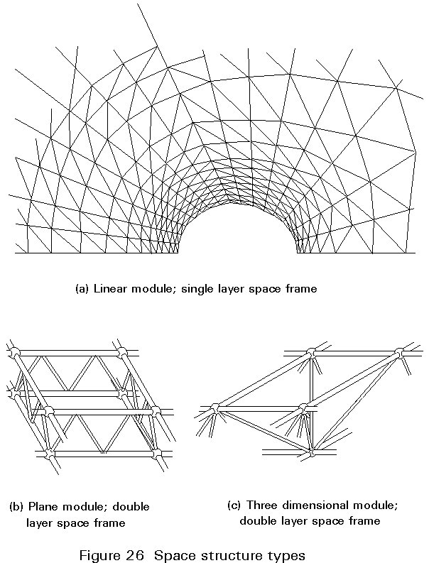
Space structures consist of identical elements, designated as modules, joined together to make a load-bearing framework. The module can be linear, plane or three dimensional (Figure 26). The members of a space structure are often in an isotropic state as regards buckling and bearing loads which are either tension or compression. Hollow sections, especially circular ones, are extremely well adapted as space frame members.
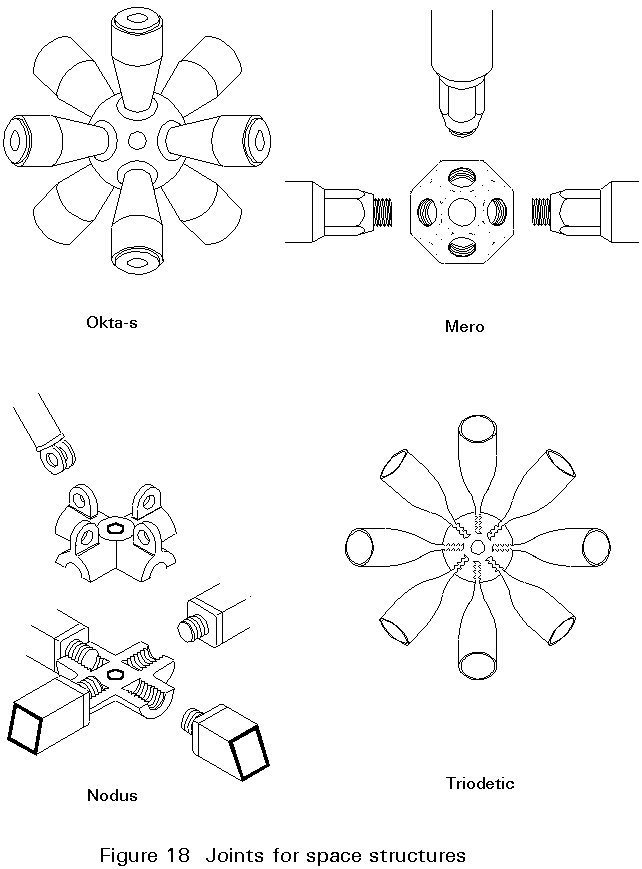
Due to the special end shaping needed for the direct connection of the hollow sections, special connectors have been developed. Examples are given in Figure 18. The development of space structures was stimulated by the availability of these prefabricated connectors and later by the development of computers and matrix calculation methods.
Although space frames with connectors are characterized by their economy due to manufacture of the structural parts on a mass production basis and simplified assembly through repeated similar operations, they are still relatively expensive. Therefore, they are applied mostly when an architect prefers them for aesthetic appearance or some special requirements, such as very large span.
Connections for concrete filled hollow sections are in general similar to those for ordinary hollow sections. The transverse force at the connection is carried only through the steel mantle. Further transmission into concrete is only possible through the clamping effect. The determination of this load by calculation is hardly possible.
The connections transmitting the load through the steel mantle are, of course, to be applied only for relatively lower load, unless a composite medium, such as a dowel or plate, can be arranged on the inside of the cross-section.
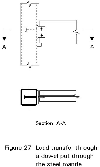
Figure 27 shows a solution to this problem. In this case, a dowel connected to the connection plate or profile is introduced through a drilled hole into the hollow section wall and the column is filled with concrete later. A horizontal tensile force can be transmitted here.
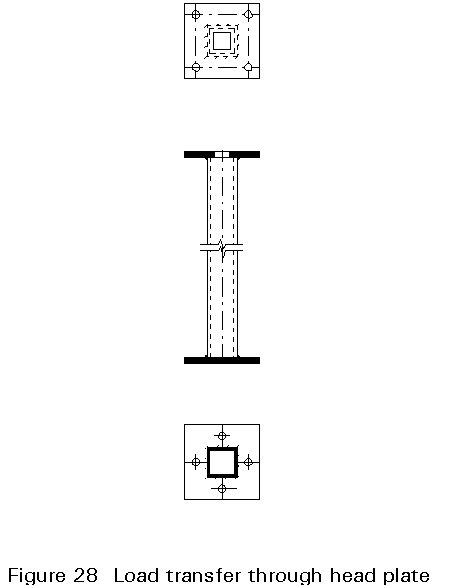
The load transfer through concrete-filled columns of multi-storey buildings (Figure 28) does not, in general, present any problem, as head plates can be used. A head plate acts as a dowel performing load transmission.
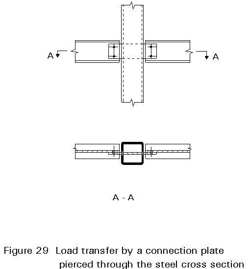
The connecting plate shown in Figure 29 can pass through the steel hollow section to provide an inner connection with a continuous column. Tests have shown that a very high load can be transmitted to the concrete using this form of construction.
Connections between open and hollow sections made by bolting using gusset plates enable the designer to select member sizes suitable to transfer the applied loads quite independently of the detail design requirements of the connection. Detail design is generally left to the fabricator.
In welded hollow section construction, where gusset plates are completely dispensed with, members are connected together directly by welding. The strength of the connection is no longer independent of the geometry and strength of the members. Joint performance needs to be considered therefore at the time member sizes are being determined. Hence, in designing hollow section structures, it is important that the designer considers the joint behaviour right from the beginning. Designing members of, for example, a girder based on member loads only may result in the use of undesirable stiffening of joints afterwards. This does not mean that the joints have to be designed in detail at the conceptual phase. It only means that chord and bracing members have to be chosen in such a way that the main governing joint parameters (such as diameter or width ratio, thickness ratio, chord diameter or width-to-thickness ratio, gap between bracings, overlap of bracings, and angle between bracing and chord) provide an adequate joint strength [5 - 10], and economical fabrication, see Lecture 13.2 and Lecture 13.3.
Since the design is always a compromise between various requirements, such as static strength, stability, economy in fabrication and maintenance, which are sometimes in conflict with one another, the designer should be aware of the implications of a particular choice.
The following guidance is given in relation to optimum design:
Chord members loaded in compression, however, always have to be checked for the bending effects of noding eccentricity, i.e. designed as beam-columns, with all the moment due to noding eccentricity distributed to the chord sections.
Full overlapping results in an eccentricity e » 0,55do or ho, but provides a more straightforward fabrication than partial overlap joints and a better strength behaviour than gap joints.
In a good design, a minimum gap should be provided such that the gap g ³ t1+t2, so that the welds do not overlap each other. On the other hand, the overlap should be at least 25% in overlap joints.
The design of hollow section trusses should be approached in the following way to obtain efficient and economical structures:
The effective length for the bracings can be assumed conservatively to be 0,75 times the system length. A more precise calculation method for the effective length is given in Eurocode 3, Annex K [1].
If welds are proportioned on the basis of particular loads in the bracing members, the designer must recognize that the entire length of the weld may not be effective, and the model for the weld resistance must be justified in terms of strength and deformation capacity [9].
Structural hollow sections have excellent static properties, not only with regard to buckling and torsion, but also in the overall design of members. They can offer economic advantages compared to open sections.
The closed shape and the smooth changeover from one section to another at joints reduces the costs of corrosion protection. It is possible to change the strength by varying the wall thickness or by filling the section with concrete without changing the outside dimensions.
The inner space gives possibilities for the combination of the strength function with others, e.g. fire protection, heating, ventilation, etc. The rational application of hollow sections will, in general, lead to clean, spacious, functional structures which appeal to architects. Circular hollow sections often offer a decisive advantage with regard to structures exposed to air or water flow. In other situations, square and rectangular hollow sections are favoured because they use simple connections with straight end cuts of the connecting members. To reduce the number of joints and to obtain a better joint strength, a Warren-type truss is preferred to a Pratt type.
Although the unit material cost of hollow sections is higher than for open sections, a proper use will lead to economical designs. Good design in hollow sections does not mean "change the members of an open section design to hollow sections", but means making use of their specific properties right from the beginning.
For long span trusses, a double chord may have advantages. The length of the bracings and the end cut are not critical regarding fitting and welding. If possible, beam-to-beam connections should be designed as simple shear connections omitting large plates.
The most important point is simplicity; gussets and stiffening plates should be avoided as far as possible, i.e. the direct connection of the members to one another should be used for preference. Consequently, the joint strength has to be considered at the commencement of the design and not later.
Thanks to the extensive research work on nearly all aspects of the structural applications in the last twenty five years, the hollow section is now in a position that it can really compete with other steel sections.
The communications of international committees, such as the Comité International pour le Développement et l'Etude de la Construction Tubulaire CIDECT (International Committee for the Development and Study of Tubular Structures) and the International Institute of Welding made a better exchange of knowledge possible. Due to the extensive coordinating efforts of these organizations, identical design rules and joint strength formulae are now used in most countries of the world, e.g. EC-countries, Canada, Japan, U.S.A. (partly), Scandinavian countries, Australia, etc.
[1] Eurocode 3: "Design of Steel Structures" - Annex K: Hollow Section Lattice Girder Connections, ENV 1993-1-1, CEN, 1992
[2] Richter, A.: Wind forces on square sections with various corner radii, Investigations and evaluations, CIDECT Report 9D/84-21.
[3] Eurocode 4: "Design of Composite Steel and Concrete Structures" ENV 1994-1-1: Part 1.1: General Rules and Rules for Buildings, CEN (in press).
[4] DIN 2916: 19875 - Bending Radii for Beams and Welded Structures; Design Sheet.
[5] ECSC-CIDECT: Construction with hollow steel sections, ISBN 0-9510062-0-7, first edition, December 1984.
[6] Wardenier, J.: Hollow section joints, Delft University Press, Delft, The Netherlands, 1982.
[7] Packer, J. A, and Henderson, J. E.: Design guide for hollow structural section connections, 1992.
[8] Wardenier, J., Kurobane, Y., Packer, J.A., Dutta, D., Yeomans, N.: Design guide for circular hollow section (CHS) joints under predominantly static loading, Ed. by CIDECT, Verlag TÜV Rheinland, Cologne, 1991.
[9] Packer, J.A., Wardenier, J., Kurobane, Y., Dutta, D., Yeomans, N., Hendersen, J.E.: Design guide for rectangular hollow, section (RHS) joints under predominantly static loading, Ed. .by CIDECT, Verlag TÜV Rheinland, Cologne, 1992.
[10] Wardenier, J., Giddings, T.W.: The strength and behaviour of statically loaded welded connections in structural hollow sections, CIDECT, Monograph No. 6, 1986.
[11] EN 10210, Part 1 pr EN 10210-1 Hot Finished Steel Hollow Sections Technical Delivery Requirements (Draft).
[12] Rondal, J., W_rker, K.G., Dutta, D., Wardenier, J., Yeomans, N.: Structural stability of hollow sections, Ed. by CIDECT, Verlag TÜV Rheinland, Cologne, 1992 (in press).
Table 1 Steel grades for structural steels
|
Steel grade
|
Minimum yield strength fy (N/mm2)
|
Tensile strength fu (N/mm2)
|
Minimum percentage elongation
|
|
|
Longitudinal |
Transverse |
|||
|
S235 |
235 |
340-470 |
26 |
24 |
|
S275 |
275 |
370-540 |
24 |
22 |
|
S355 |
355 |
470-630 |
22 |
20 |
|
Fe 460* |
460 |
550-720 |
17 |
15 |
*
from EN 10210, Part 1 [11]
Table 2 Increase of yield strength due to cold forming of hollow sections
|
Average yield strength: The average yield strength fya may be determined from full size section tests or as follows: fya = fyb + (k× n× t2/A) × (fu-fyb) where fyb, fu is the specified tensile yield strength and ultimate tensile strength of the basic material (N/mm2) t is the material thickness (mm) A is the gross cross-section area (mm2) k is the coefficient depending on the type of forming (k = 7 for cold rolling) n is the number of 90° bends in the section with an internal radius <5t (fractions of 90° bends should be counted as fractions of n) fya should not exceed fu or 1,2 fyb The increase in yield strength due to cold working should not be utilised for members which are annealed* or subject to heating over a long length with a high heat input after forming, which may produce softening. |
|
Basic material: Basic material is the flat hot rolled sheet material out of which sections are made by cold forming. |
*
Stress relief annealing at more than 580° or for over one hour may lead to deterioration of the mechanical properties.
Table 3 Minimum corner radii of cold finished RHS
|
Steel grade |
Wall thickness t (mm) |
minimum |
|
S235 S275 S355 |
12 < t £ 16 8 < t £ 12 6 < t £ 8 t £ 6 |
3,0 2,0 1,5 1,0 |
Table 4 European buckling curves according to manufacturing processes
|
Cross-section |
Manufacturing process |
Buckling curves |
|
Fig T4 1 |
Hot forming |
a |
|
Cold forming (fyb* used) |
b |
|
|
Cold forming (fya** used) |
c |
*
fyb = yield strength of the basic material**
fya = yield strength of the material after cold forming
Table 5 Buckling length of a bracing member in a lattice girder
|
d0 outer diameter of a circular chord member d1 outer diameter of a circular bracing member b0 external width of a square chord member b1 external width of a square bracing member |
b
= |
|
for all b : lb /l £ 0,75 |
|
|
calculate width:
|
|
Table 6 Torsional strength of various sections
|
Section |
Mass, kg/m |
Torsion constant J |
|
150 UC 23 200 UB 25 L 127 x 127 x 13 ¨ 127 x 127 x 6,3 f 168 x 6,3 |
23,4 25,4 24,0 23,9 25,3 |
48,7 61,2 166 11200 21200 |
Table 7 Local buckling limits for hollow sections
|
Section |
¡ |
¨ |
|
Plastic design sections |
|
|
|
Compact sections |
|
|
|
Elastic design sections |
|
|
|
|
Local buckling check for sections with larger d/t or b/t ratios |
|
|
e = |
||
Table 8 Drag coefficients for I-profile and hollow sections
|
Section |
Drag coefficient |
|
Circular Hollow Section See Fig T8-1 |
0,5 - 1,2 |
|
Rectangular Hollow Section See Fig T8-2 |
0,6 - 2,0 |
|
Open Rolled Sections See Fig T8-3 |
2,0 |
Table 9 Minimum bending radii for RHS
|
D mm |
t mm |
ri mm |
|
20 30 40 50 60 |
2,6 2,6 2,6 3,2 4,0 |
5D |
|
70 80 90 100 120 150 |
5,0 5,0 6,3 6,3 6,3 10,0 |
6D |
|
180 200 250 300 |
10,0 10,0 12,5 16,0 |
7D |
|
350 400 450 |
16,0 16,0 16,0 |
8D |