ESDEP WG 13
TUBULAR STRUCTURES
To gain an understanding of the fundamental behaviour of connections between circular hollow sections.
Lectures 2.3: Engineering Properties of Steels
Lectures 3.1: General Fabrication of Steel Structures
Lecture 11.1.2: Introduction to Connection Design
Lecture 13.1: Application of Hollow Sections in Steel Structures
Lectures 12.4: Fatigue Behaviour of Hollow Section Joints
Lecture 13.3: The Behaviour and Design of Welded Connections between Rectangular Hollow Sections (RHS) under Predominantly Static Loading
Circular hollow sections (CHS) have been used in steel structures for many years. The most common form of connection in CHS construction is that in which the bracings are shaped to fit the circular profile of the chord and then welded to it.
The behaviour of welded, unstiffened CHS joints under static loading is discussed in this lecture, with emphasis on the connection behaviour and the governing connection parameters. Based on simplified theoretical models and test results, semi-empirical strength formulae for connections are given, which have been adopted in Eurocode 3 [1].
The notation in Eurocode 3, Annex K [2], has been adopted.
The advantages of using circular hollow sections in steel structures are described in Lecture 13.1. Although bolting is used for connections in prefabricated substructures and in the assembly of proprietary types of space frames, it is much more common to use welded connections, particularly for lattice type constructions.
This lecture deals mainly with unstiffened welded connections between circular hollow sections. The behaviour of the connection is explained based on the assumption that the strength of the weld is adequate.
The design philosophy to execute hollow section joints is given in Lecture 13.1, whilst Lecture 13.3 deals with the design of welded, unstiffened joints between rectangular hollow sections.
For jointing circular chords with circular bracings in a lattice structure, the ends of circular bracings are usually cut as "saddles" (saddle profiling) by manual or automatic flame cutting. They are then welded together.
The complex load transfer and non-linear local stiffness distribution in CHS joints made it necessary to carry out extensive investigations into the joint behaviour. Theoretical model analysis and experimental results have led to design rules and semi-empirical design formulae for the basic types of CHS joints [3-6]. They are incorporated in Eurocode 3, Annex K [2].
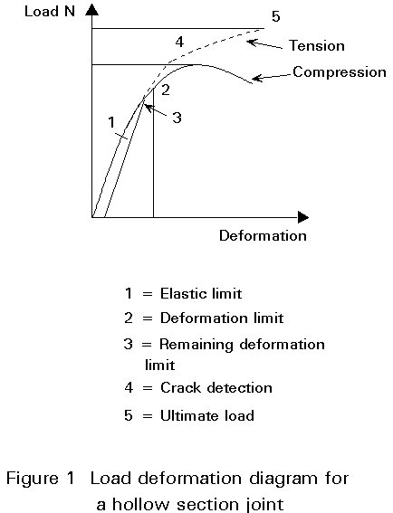
The load-bearing behaviour of hollow section joints is governed, on the one hand, by the joint geometry and, on the other hand, by the resulting locally effective loads longitudinal and transverse to the axis of the members. The behaviour of CHS joints has been examined in both the elastic and the post-elastic range up to their ultimate resistance. As the diagram of load against deformation (Figure 1) shows, the static strength of a hollow section joint can be characterized by the following criteria:
When large compression forces are present in combination with thin-walled sections, instability failures can occur (low deformation capacity). In other circumstances, it is usual for the joint to show considerable post-elastic resistance. Failure occurs when sufficient area of the joint has reached the yield stress or stresses up to ultimate stress, such that further increases in load cannot be resisted.
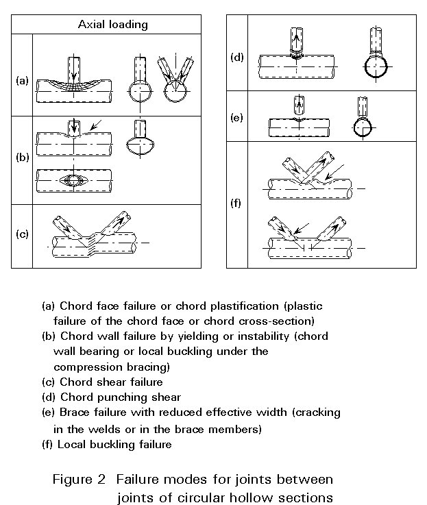
Internationally, it has become common practice to base the design resistances for joints of circular hollow sections on the limit state criteria based on the failure modes given in Figure 2. They depend on specific geometrical parameters and loading conditions.
Based on theoretical investigations with analytical models, which are described later in this lecture, and the results of the strength tests on experimental joints, the following general equation to describe the ultimate joint strength Nu has been derived:
Nu = fyo . to2 f1 (b) . f2 (g) . f3 (q) . f4 (kg) . f (kp)
For the explanation of the symbols, see Eurocode 3, Annex K [2].
Three models for the determination of the influencing parameters are currently used. The models are:
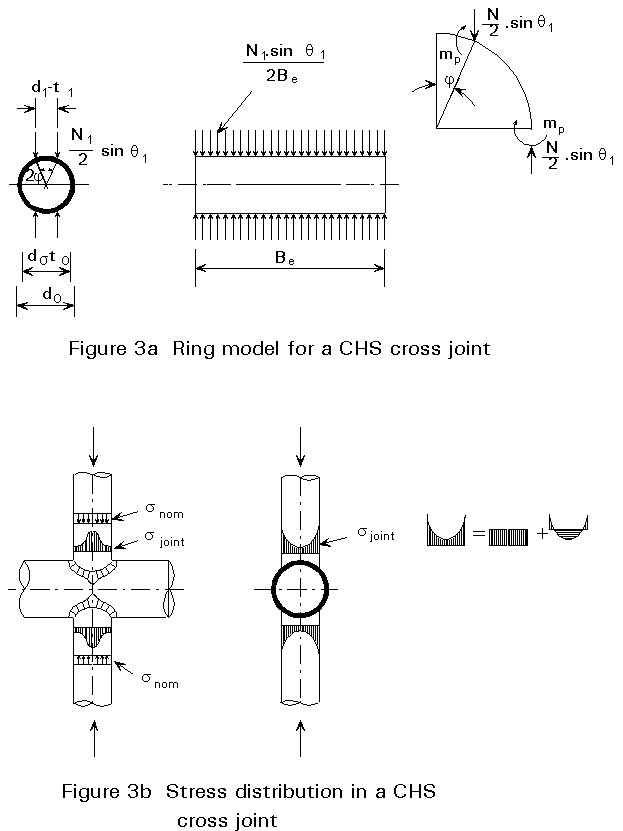
The design of CHS joints was initially based on the strength obtained from a rigid plastic analysis of a two-dimensional ring, used to represent a CHS cross joint assuming point loads at the brace faces. The joint is schematized to a ring with an effective length Be and the same geometrical and mechanical properties as the chord (Figure 3a).
Figure 3b shows the non-uniform stress distribution at the intersection of bracing and chord for T-, Y- and X-joints. Two line loads equal to half the bracing loads represent the loading system for a cross joint.
Neglecting the influence of axial and shear stresses, the plastic moment mp can be calculated by the following equation:
![]() (1)
(1)
where
N1y is the load based on the yield strength of the ring.
q
1 is the angle between the chord and the brace.Taking account of the effective length Be of the ring, the plastic moment is given by:
![]() (2)
(2)
Substituting Equation (2) in Equation (1) and assuming sin y » b and ![]() gives:
gives:
![]() (3)
(3)
where
b
is the ratio brace to chord diameterThe effective length Be for different types of connections is determined experimentally. Furthermore, the term (1 - b) has to be corrected to avoid an infinitive strength for b = 1,0. Consequently, Equation (3) changes to:
![]() (3a)
(3a)
where
Co and C1 are constants.
For T-, Y- and X-joints reasonable agreement between test results and the semi-analytical ring model can be obtained. In more complicated joints, such as K- and N-types, other influencing parameters, i.e. gap between bracings and the presence of membrane forces have to be considered.
This model is illustrated in Figure 4 for the case where a Y-joint is loaded in tension. It is assumed that the shear stress in the chord face around the perimeter of the bracing is uniform on the plan area of the connection, i.e. the effect on the bracing perimeter on the curvature of the chord is not taken into account.
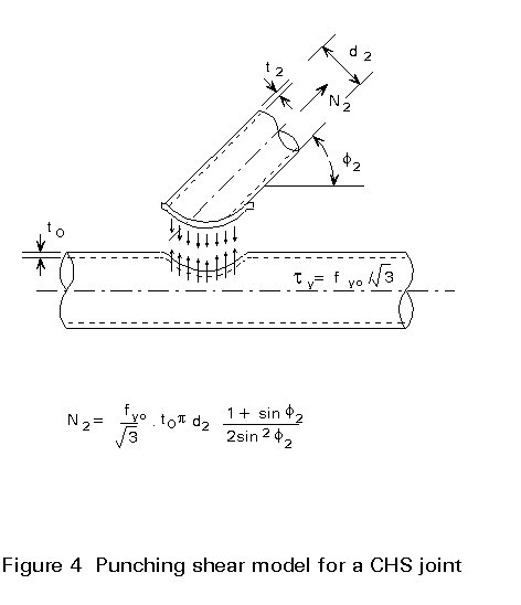
For joints with q2 = 90° , the theoretical uniformly distributed punching shear stress at its limiting value ![]() can be calculated as follows:
can be calculated as follows:
![]() (4)
(4)
For joints with bracings with q2 < 90° , the punching shear area is increased by a factor ![]() . Furthermore, punching shear is only caused by the load component perpendicular to the chord, i.e. N2 . sin q2, which leads to the following equation:
. Furthermore, punching shear is only caused by the load component perpendicular to the chord, i.e. N2 . sin q2, which leads to the following equation:
![]() (5)
(5)
In general, this criterion is only applicable for joints with small b values, since, as the value of b increases, the applied load will be transferred by hoop stress to the chord.
The presentation of design rules in terms of punching shear is widely used in offshore recommendations.
As shown in Figure 5, in K- or N-type joints with a gap, the chord cross-section at the gap location can fail due to shear or a combination of shear, axial load and moment. When the chord section is compact, the following formulae for the plastic design can be applied:
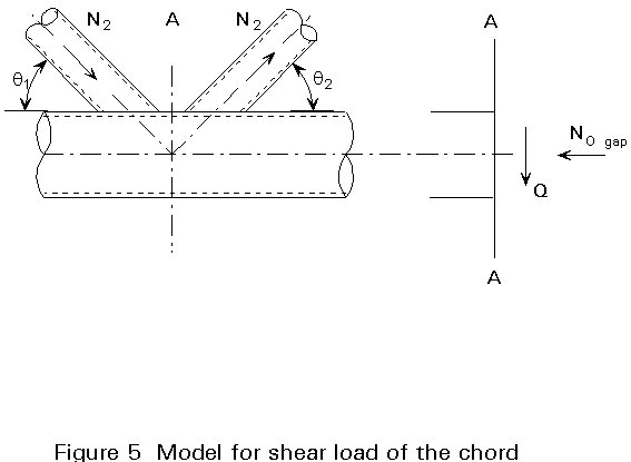
Ni sin qi £ 2 ![]() . (do - to) . to
(6)
. (do - to) . to
(6)
No gap £ p . (do - to) . to . fyo (7)
Mo gap £ (do - to)2 . to . fyo (8)
Generally, the moments are small and only the interaction between axial load and shear load has to be considered:
 (9)
(9)
In joints with small gaps, the cross-section of the chord is stiffened by the connected bracings which increases the shear load resistance considerably.
Virtually all of the available test evidence on connections between circular hollow sections has been obtained from isolated joint specimens of the form shown in Figure 6. A few tests are known where the joints have been tested in complete frames. The majority of tests has been carried out in Japan, the U.S.A., the Netherlands, the United Kingdom and Germany.
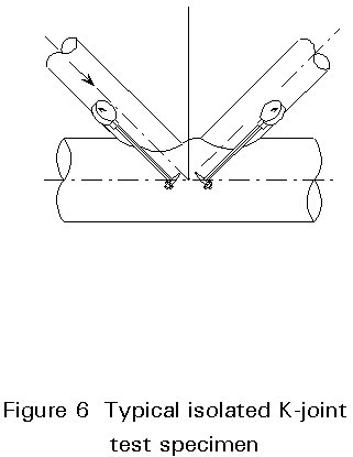
The range of the chord diameters tested varied from 50 to 508 mm with different geometrical parameters (b, g, q, kg, kp, etc.) of the joint and mechanical properties.
The experimental evidence generated by many investigators has been used in combination with the analytical models described in Section 3 to derive joint resistance equations for the mean joint strength. Characteristic joint strength formulae have been determined based on a statistical analysis taking account of the scatter in test results, the tolerances in dimensions and the variation in mechanical properties. The characteristic joint strength formulae divided by a partial factor gm gives the design resistance formulae. The validity of the resulting semi-empirical design resistance formulae is restricted to the parametrical ranges of the experimental evidence.
The most recent design recommendations for uni-planar axially loaded T-, Y-, X- and K-joints of circular hollow sections have been derived from the research by IIW and CIDECT. The semi-empirical formulae for design resistance for uniplanar CHS joints have been adopted by Eurocode 3, Annex K [2], and are given in Tables 1a and 1b.
The design resistance formulae for T-, Y-, X- and K-joints have been based on the joint resistance under compression loading, but can also be used for tensile loading. The ultimate resistance under tensile loading is higher than that under compressive loading (see Figure 1). However, it is not always possible to take advantage of this joint resistance due to the reduced deformation capacity.
The design resistance is generally governed by two criteria, i.e. plastification of the chord cross-section and chord punching shear. Both criteria have to be checked using the formulae in Table 1.
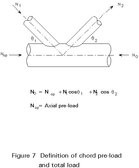
For the factor Kp expressing the effect of prestress on the joint resistance, only the prestress of the chord has to be considered. Thus the horizontal bracings load components have to be extracted, see Figure 7.
Tubular joints can have various configurations and loading conditions, in addition to the basic types of joints described above. However, the design strength of these joints (see Table 2) can generally be related to that of the basic types.
The joints can be divided into two basic groups, those with gusset plates symmetrically welded to the opposite sides of the chord (XP-joints) and those with gusset plates only welded to one side of the chord (TP-joints).
The XP-joints show a behaviour comparable to that of X-joints, whereas the TP-joints can be related to T-joints.
Joints with a plate in the longitudinal direction show very high deformations at the maximal load resistance. The load deformation diagrams of these joints show a more pronounced yield load resistance than tubular joints. Although the deformations at this "yield load resistance" can still be considerable, the yield load resistance is used in the analysis.
Table 3 gives the design resistances of various joints under axial load, in-plane bending moment and out-of-plane bending moment.
The design resistance formulae for CHS joints loaded by bending moments are derived in a similar way to those for axially loaded joints (see Table 4). When the members are not critical and the welds are strong enough, two main modes of failure exist in principle: (a) plastic failure of the chord face or chord cross-section, and (b) cracking leading to rupture of the bracing from the chord.
Finite element calculations have shown that multi-planar members and multiplanar loading show substantial differences in the resistance and stiffness compared to a uniplanar X-joint. Various tests on K-joints in triangular girders led to an interaction equation, which can easily be replaced by a constant of 0,9, to be applied to the resistance of uniplanar joints.
For T-joints, tests carried out on double T-joints (V-joints) with a 90° included angle between bracings and both bracings loaded in compression, showed that the resistance of the multi-planar joint did not vary substantially from the uniplanar joint resistance. Table 5 gives simplified design recommendations for CHS multi-planar joints using the strength formulae for uniplanar joints with correction factors.
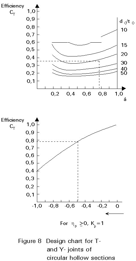
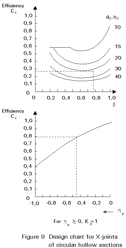
To judge whether the joint resistance is sufficient for the selected members, a designer often requires a checking 'tool'. This tool is provided by the design charts given in Figures 8-12, where the design resistances are presented graphically in terms of bracing efficiency Ce, i.e the design resistance N1Rd of the joint divided by the yield load A1× fy1 of the connected bracing [7].
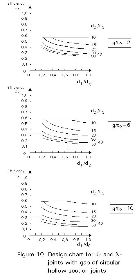
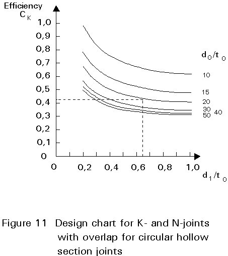
The following formula is obtained for the efficiency:
![]() (10)
(10)
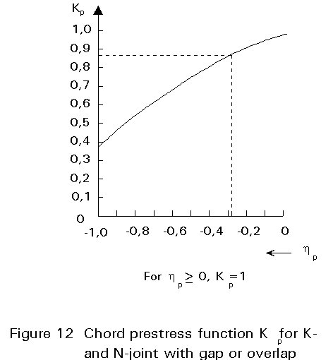
The efficiency parameter Ce (CT for T- and Y-joints, CX for X-joints and CK for K- and N-joints) gives the efficiency for a joint with Kp = 1,0, a bracing inclination q1 = 90°, and an identical wall thickness and design yield stress for the chord and bracing members.
The design charts also show the factor Kp depending on np = sop/fyo
For lattice girders simply supported at the ends of a span, the prestressing is small at the girder ends, where bracing loads are highest. The prestressing is high where the bracing loads are low (in the centre). For continuous lattice girders, Kp needs special attention at the supports.
The design procedure for the design of lattice girders is given in Lecture 13.1.
[1] Eurocode 3: "Design of Steel Structures": ENV 993-1-1: Part 1.1: General Rules and Rules for Buildings, CEN, 1992.
[2] Eurocode 3: ENV 993-1-1: Annex K: Hollow Section Lattice Girder Connections, CEN, 1992.
[3] Wardenier, J.: Hollow section joints, ISBN 90-6275-084-2, Delft University Press, Delft 1982.
[4] Wardenier, J., Giddings, T.W.: The strength and behaviour of statically loaded welded connections in structural hollow sections, CIDECT Monograph No.6, 1986.
[5] Wardenier, J., Stark, J.W.B.: The static strength of welded lattice girder joints in structural, hollow sections, ECSC Report EUR 6428C MF 1980.
[6] Packer, J. A. and Henderson, J. E.: Design guide for hollow structural section connections, Canadian Institute of Steel Construction, 1992.
[7] Wardenier, J., Kurobane, Y., Packer, J.A., Dutta, D., Yeomans, N.: Design guide for circular hollow section (CHS) joints under predominantly static loading, CIDECT publication, Verlag TÜV Rheinland, 1991, ISBN 3-88585-975-0.
[8] Design recommendation for hollow section joints - predominantly statically loaded. 2nd Ed., IIW Doc. XV-701-89, September 1989, International Institute of Welding.
|
TYPE OF JOINT |
DESIGN RESISTANCE (i = 1,2) |
|
T- and Y-joints |
CHORD PLASTIFICATION |
See Fig T1-1 |
|
|
X-joints |
CHORD PLASTIFICATION |
See Fig T1-2 |
|
|
K- and N-gap or overlap joints |
CHORD PLASTIFICATION |
See Fig T1-3 |
|
|
PUNCHING SHEAR |
|
|
T-, Y- and X-joints K-, N- and KT-joints with a gap If: d1 £ d0 - 2to |
|
|
FUNCTIONS |
|
|
kp = 1,0 for np ³ 0 (tension) kp = 1 + 0,3 (nP - nP2 ) for np < 0 (compression) but kp £ 1,0 |
|
|
|
|
Table 1a Design resistance of welded joints between circular hollow sections
|
|
|
|
|
|
g ³ t1 + t2 |
l ov ³ 25% |
|
q 1 ³ 30° |
|
Table 1b Range of validity for welded joints between circular hollow sections
|
TYPE OF JOINT |
CHECK OF THE JOINT DESIGN RESISTANCE (i = 1,2) |
| See Fig T2-1 |
Ni.Sd £ Ni.Rd Ni.Rd from X joint |
|
See Fig T2-2 |
N1.Sd sin q 1 + N3.Sd sin q 3 £ N1.Rd sin q 1 N2.Sd sin q 2 £ N1.Rd sin q 1 N1.Rd from K-joint
replace |
|
See Fig T2-3 |
N1.Sd sin q 1 + N2.Sd sin q 2 £ N1.Rd sin q i N1.Rd from X-joint where N1.Rd sin q 1 is the larger of N1.Rd sin q i and N2.Rd sin q 2 |
|
See Fig T2-4 |
Ni.Sd £ N1.Rd N1.Rd from K-joint in addition: check design resistance of cross-section in 1-1 (gap joints only)
|
Table 2 Design resistance of special types of welded joints between circular hollow sections
|
TYPE OF JOINT |
DESIGN AXIAL RESISTANCE N1.Rd |
DESIGN IN PLANE MOMENT RESISTANCE Mip.1Rd |
DESIGN OUT OF PLANE MOMENT RESISTANCE Mop.I.Rd |
|
8 |
XP1 |
|
- |
0,5 b1 N1.Rd: NiRD from (XP1 or TP1) |
|
TP1 |
|
|||
|
B = ti /bo but B £ 0,2 9 |
XP2 |
|
h1 N.Rd: NiRD from (XP2 or TP2) |
- |
|
TP2 |
|
|||
10 |
XP4 |
|
h1 N1.Rd: NiRD from (XP1 or TP1) |
0,5 b1 N1.Rd: NiRD from (XP4 or TP4) |
|
TP4 |
|
|||
11 |
XP5 |
|
h1 N1.Rd: NiRD from (XP5 or TP5) |
0,5 b1 N1.Rd: NiRD from (XP5 or TP5) |
|
TP5 |
|
|||
|
General: Punching shear check: For TP5/XP5 (s a + s b ) t1 £ 0,58 fyo to [1,1/gmj] For other joints (s a + s b ) t1 £ 1,16 fyo to [1,1/gmj] |
Range of validity see Table 1b except b ³ 0,4 and h £ 4 Special functions see Table 1a
h
=
b
= |
|||
Table 3: Design resistances of welded CHS joints with gusset plates or sections

|
TYPE OF JOINT |
DESIGN RESISTANCE (i = 1,2) |
|
T-, Y- and X-joints |
CHORD PLASTIFICATION |
|
|
|
|
T-, Y-, X-, K- and N-joints |
CHORD PLASTIFICATION |
|
|
|
|
T-, Y- and X-joints K- and N- joints with a gap
If: d1 £ d0 - 2to |
PUNCHING SHEAR |
|
|
|
|
Range of validity see Table 1b Special functions see Table 1a |
|
Table 4: Design resistance of welded joints between circular hollow sections loaded by bending moments
|
TYPE OF JOINT |
CORRECTION FACTOR TO UNIPLANAR JOINTS |
60° £ _ £ 90° TT-Joint |
1,0 |
XX-Joint See Fig T5-2 |
1 + 0,33 take into account of the sign of N1.Sd and N2.Sd ½ N2.Sd½ £ ½ N1.Sd½ |
60° £ _ £ 90° KK-Joint See Fig T5-3 |
0,9 in addition: check design resistance of cross section in 1-1 (gap joints only)
|
|
Range of validity see Table 1b |
|
Table 5: Correction factors for the determination of multi-planar CHS joint strength