ESDEP WG 13
TUBULAR STRUCTURES
To gain an understanding of the fundamental behaviour of rectangular hollow section joints.
Lectures 2.3: Engineering Properties of Steels
Lectures 3.1: General Fabrication of Steel Structures
Lecture 11.1.2: Introduction to Connection Design
Lecture 13.1: Application of Hollow Sections in Steel Structures
Lecture 13.2: The Behaviour and Design of Welded Connections between Circular Hollow Sections (CHS) under Predominantly Static Loading
Lectures 12.4: Fatigue Behaviour of Hollow Section Joints
The economy of hollow section structures is not only governed by the geometrical properties of the hollow section members, but to a large extent by the connections. To avoid stiffening of connections, a designer needs to consider the connections in the conceptual phase.
In this lecture, the static strength criteria for various unstiffened truss-type connections of rectangular hollow sections are discussed. Emphasis is given to the connection behaviour and governing connection parameters determined with simple analytical models, which relate to the particular failure modes. Based on these simplified models and experimental evidence, semi-empirical limit state design formulae have been developed, which have been adopted by Eurocode 3 [1].
The notation in Eurocode 3, Annex K [2], has been adopted.
Hollow sections are mainly used in truss or lattice type structures, where they are welded to one another directly without gusset or stiffening plates. The connection strength largely governs the selection of the members in this form of construction. Consequently, the designer should have a good insight into the behaviour of hollow section connections and the parameters which influence the strength of these connections.
The general philosophy of the design of hollow section structures has been described in Lecture 13.1, while Lecture 13.2 discusses the design of circular hollow section joints. In principle, these lectures both apply also to joints between rectangular hollow sections. The advantage of rectangular hollow sections over circular hollow sections is, however, the easier and more economical fabrication of joints (flat cuts).
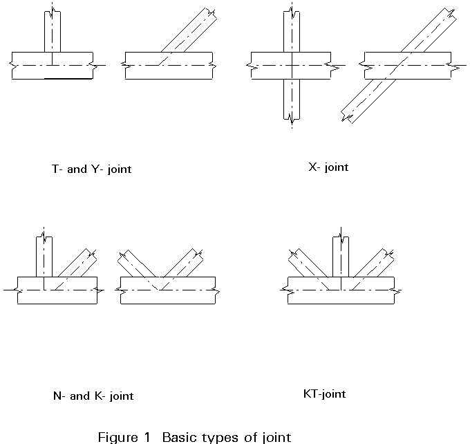
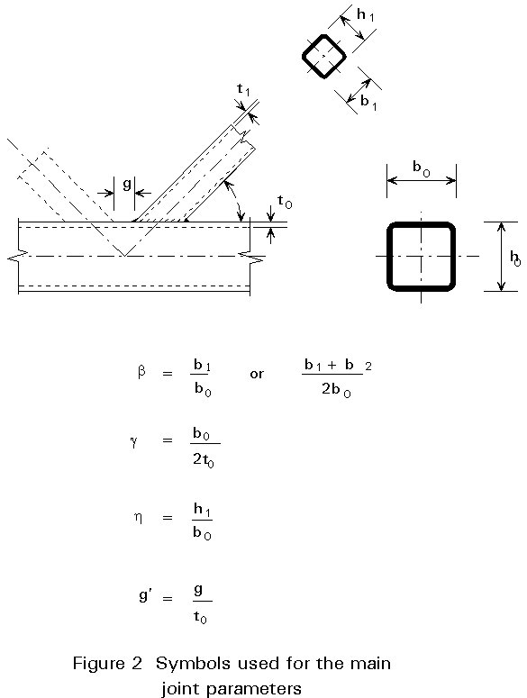
Figure 1 shows the most common types of joints. The geometry of the joints is described by the main parameters shown in Figure 2.
Due to the various geometrical parameters of rectangular hollow sections (rectangularity) and the variety in combination of sections, more failure modes have to be considered.
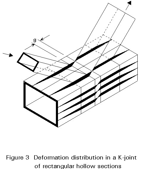
Due to the complex load transfer and deformation distribution (Figure 3), research programmes have been carried out to investigate the joint behaviour. Based on analytical models and experimental results, design rules and formulae have been established for the basic types of joints [3-6].
In general, the static strength can be characterized by the criteria shown in Figure 4, i.e.:
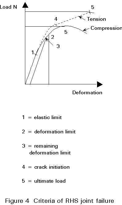
However, the ultimate load resistance is well defined for joints loaded in compression and chosen as the basis for the determination of the static strength. Because of the non-linear load deformation behaviour, there is no international agreement regarding the deformation criterion or the determination of the yield load for joints made of hollow sections. However, in those cases where the ultimate load is reached after excessive deformation (e.g. T, Y and X joints), the expressions for the joint strength take account indirectly of a deformation limit (about 0,01 bo at service load condition). This procedure is to avoid two checks, i.e. one for joint resistance and one for stiffness. To avoid too high deformations or, on the other hand, to include additional safety with a lower deformation capacity for joints loaded in tension, the same strength as for joints loaded in compression has been adopted.
Depending on the type of joint, the joint parameters and the loading conditions, several modes of failure can occur, as illustrated in Figure 5.
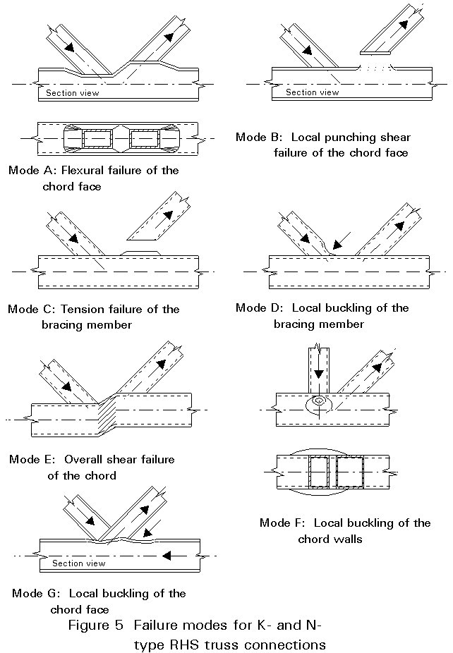
A. Plastic failure of the chord face or chord cross-section
B. Tearing in the chord by the rupture of the tension bracing from the chord (punching shear)
C. Rupture of the welds or in the tension bracing itself (termed as "effective width" failure)
D. Local buckling of the compression bracing (also termed as "effective width" failure)
E. Overall (entire chord section) shear failure of the chord
F. Chord wall bearing failure or local buckling of the chord under the compression bracing
G. Local buckling of the chord face behind the heel of the tension bracing
On many occasions, failure occurs by combinations of the basic types mentioned above. Plastic failure of the chord face is the most common failure mode (modeA) for gap joints with small to medium width ratios b between the bracing and chord members. For medium width ratios (b = 0,6 - 0,8), the failure generally occurs together with tearing in the chord (mode B) or in the tension bracing (mode C), although the latter only occurs in connections with relatively thin walled bracing members. The mode involving local buckling of the compression bracing (mode D) is the most common failure mode for overlap connections. Shear failure of the entire chord section (mode E) is observed in gap connections with b close to 1,0 or chords with low depth-to-width ratios ho/bo. Local buckling failures (modes F and G) occur occasionally for connections with high slenderness bo/to. Weld failures are avoided by making the welds stronger than the connected bracings.
Lamellar tearing (more probable for heavy wall thicknesses) can be avoided by choosing suitable material qualities (low sulphur content) and suitable welding procedures (restraint).
Analytical models serve to describe the joint behaviour and give information on the influencing parameters. Models which take account of all influencing parameters are, in general, too complicated. More simplified models are used to determine the governing joint parameters for the ultimate strength and to give insight into the joint behaviour. The results of this analysis in combination with experimental evidence lead to semi-empirical formulae for joint strength.
The yield line model is much more widely used for joints between square or rectangular hollow sections than for joints between circular hollow sections. For joints with a low to medium bracing-to-chord width ratio b, the joint strength can be conservatively estimated on the basis of a simplified yield line method. This method gives an upper bound of the yield strength; therefore, various yield line patterns have to be examined in order to find the lowest value acceptable as the failure load. Many studies, however, show that the simplified yield line pattern for estimation of the yield strength of a T-, Y- or X-joint with a width ratio b < 0,8, as shown in Figure 6, gives only a marginally higher strength than that using more complicated patterns. Due to the fact that the effects of membrane action and strain hardening are ignored in the simplified yield line models, these generally underestimate the actual ultimate strength. For, T-, Y- and X-joints, the yield strength is used to avoid large deformations in actual design. For K- and N-joints, the membrane action is included in a semi-empirical way [4,5,6].
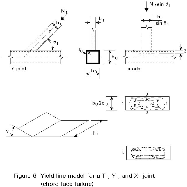
The general principle of the yield line method illustrated in Figure 6 for a Y-joint consists of equating the work of the external force N1 over a deflection d and the internal work by the plastic hinge system (length li and angle of rotation y i).
N1 . sin q1 . d = S li . yi . mpl
where mpl = ![]()
q1 is the angle between the chord and the brace member
The minimum for the load N1 can be achieved by differentiation of the above equation, resulting in:
N1 = ![]()
When the bracing is pulled away from the chord, failure can occur by cracking and possibly by rupture of the chord face as illustrated for a Y-joint in Figure 7.
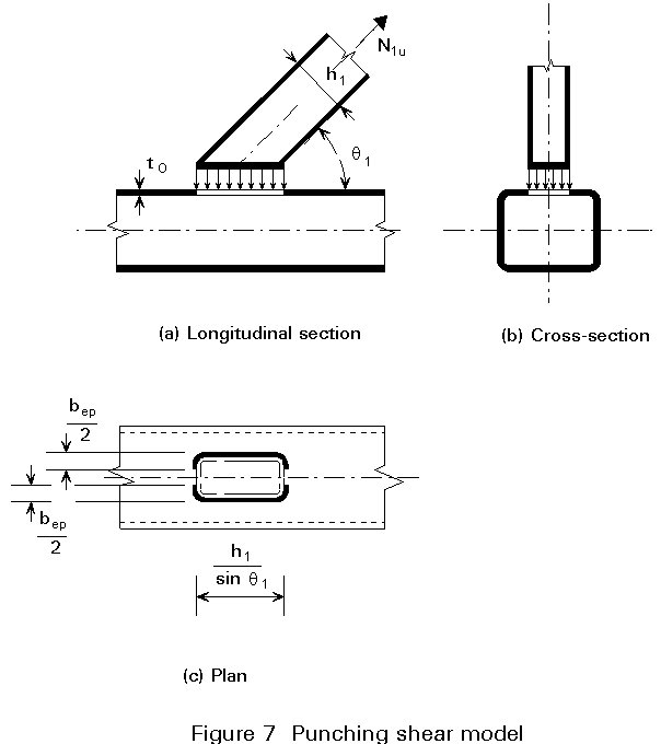
The associated punching shear strength for T-, Y- and X-joints can be expressed as:
N1 = ![]()
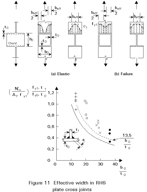
Due to the non-uniform stiffness along the section perimeter, the full perimeter cannot be fully effective. The value of the effective punching shear width bep is determined experimentally.
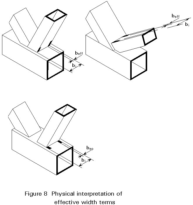
The previously described punching shear model may be governing for joints with relatively thick-walled bracings; for joints with thin-walled bracings, however, the effective width of the bracings may become critical. The strength can be expressed in a similar way to that for punching shear, but it is related to the bracing dimensions and bracing material properties.
For example, for a T-, Y- and X-joint:
N1 = fy1 . t1 (2h1 - 4t1 + 2beff)
The effective width beff (see Figure 8) is determined experimentally and becomes larger when bo/to and t1/to decrease, or when sufficient deformation can occur by yielding at the stiff parts of the intersection.
The chord shear strength of the joint can be analytically predicted using the basic formula for plastic design. The basic shear load resistance is given by:
Vp = ![]() . Av, (Figure 9).
. Av, (Figure 9).
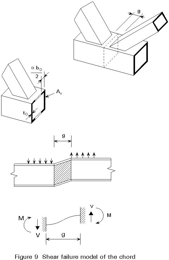
Although the chord webs would give Av = 2 ho× to, it has been confirmed by tests that for small gaps, a part of the top flange (Figure 9) is effective for shear transfer, resulting in:
Av = (2 ho + a.boto) to
where a is a function of g/to
The remaining chord cross-section area has to transmit the axial force. In general, the Hubert Hencky-von Mises criterion can be used resulting in the following interaction formula:
N0,gap.Sd £ (Ao - Av) fyo + Av . fyo 
T-, Y- and X-joints with a high b ratio may fail by yielding or buckling of the chord side walls, as shown in Figure 10. In principle, the same method is used as for beam-to-column connections between I-shaped sections (see Lecture 11.6)
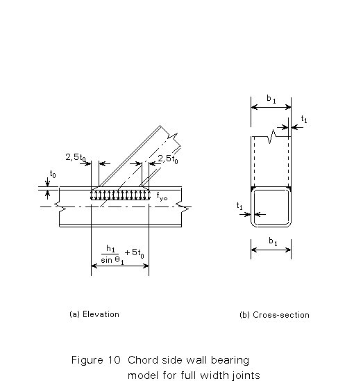
For equal width joints, the strength follows directly from the model shown in Figure 10:
N1 = 2 fyo . to ![]()
For slender walls and compression loads, fyo is replaced by a critical buckling stress fk, which is a function of the chord web slenderness ho/to.
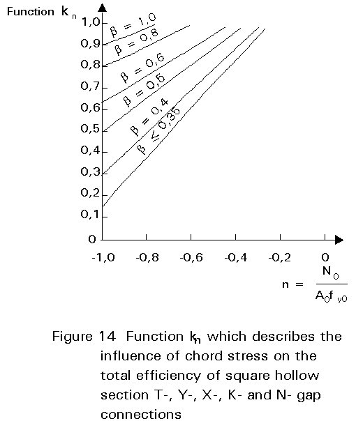
Extensive test programmes [4] have been carried out since the late 1950's to determine the ultimate strength of joints with varying parameters. The tests have been used especially to investigate the effects which cannot be determined analytically, e.g. the effective width, the influence of chord preloading, and to check the formulae derived by theoretical analysis. In those cases where the models do not predict the joint strength adequately due to, for example, membrane and strain hardening effects, the experiments are used in combination with theoretical analysis to establish semi-empirical formulae for joint strength. This procedure has been used, for example, for K-joints with gap. The effective width, shown in Figure 8, has been determined experimentally. First tests were carried out on plate to RHS chord connections (Figure 11), the results of which were used as a basis for T- X-, K-gap and K-overlap joints. The influence of prestressing of the chord (function kn) has also been determined experimentally, since the analytical expressions are too complicated to be used in practice. However, the functions obtained by experiments have been compared with analytical expressions and set so that they do not deviate too much from the analytical results.
The best available design formulae are semi-empirical (see Tables 1-4). This means that the influencing parameters have been determined with simplified analytical models, whereas the final formulae have been obtained by modification using a statistical analysis of the test results. Care has been taken that the available test evidence represents joints with various possible parameters. In order to avoid an additional check for joint deflection, the yield line model was adopted for joint geometries which show excessive deformations at ultimate loading, i.e. T-, Y- and X-joints.
Other types of joints are treated in a similar way to those discussed above.
These joints have nearly the same joint efficiency as joints of square bracings, where the joint efficiency is defined as the ratio of joint strength to the squash load Ai× fyi of the connected bracing. This implies that the same strength functions can be used as for square hollow section joints, but multiplied by ![]() (see Table 3-4).
(see Table 3-4).
The strength of plate-to-RHS chord connections (see Table 5) is governed by the same failure criteria as described above. However, a comparison of the various failure criteria shows that the effective width, the punching shear and wall bearing are the prevailing failure modes. The strength of an I-section loaded in bending and connected to an RHS chord can be directly related to that for a plate-to-RHS chord connection.
The design resistance formulae for RHS joints loaded by bending moments are derived in a similar way as for axially loaded joints (see Table 6). In order to avoid checking all failure modes, the validity have been limited to ranges where the joint strength is governed by one or two failure criteria.
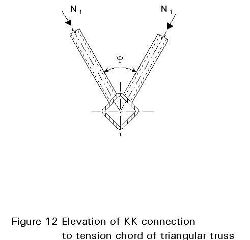
Based on analytical and experimental work on KK-connections with low to medium width ratios b between the bracing members and chord, following has been suggested: where the angle between bracing member planes y is less than 90° leading to an increase in the effective value of b at the chord face, and when the bracing members are attached to the chord face off-centre (see Figure 12), the yield strength of a triangular truss tension chord face will be greater than that of a planar truss chord face with the same size members. As further failure modes may exist over a wider range of connection parameters than those studied, and as uniplanar, K-gap connection strength is assessed on the basis of ultimate strength rather than predicted by the yield strength, a reduction factor of 0,9 is currently used in the uniplanar K-connection design formulae. Additionally, a check of chord shear has always to be performed for gap KK-connections, even for square RHS members.
For RHS 90° TT-connections, it has been found theoretically that little difference exists between the design strengths of uniplanar and multiplanar connections.
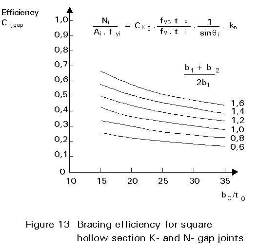
In practice, a designer needs a quick evaluation of the joint strength in order to judge whether the joint strength is sufficient for the selected members. This evaluation can be made by means of a set of consistent design charts for the preliminary design of K, N, T, Y and X connections which are based on Eurocode 3 recommendations [1]. In these design charts, the joint resistance is described in terms of an efficiency coefficient Ce, which is defined as the joint factored resistance divided by the yield load of the full section of the particular bracing member Ai× fyi for a joint with wall thickness ratio ![]() = 1, angle of bracing inclination q = 90° and the function for prestress in chord kn = 1.
= 1, angle of bracing inclination q = 90° and the function for prestress in chord kn = 1.
In general, the joint efficiency can be calculated using the following equation:
![]()
As an example, Figure 13 shows the efficiency diagram for K-joints with gap of square hollow sections, while Figure 14 describes the prestress function kn.
These diagrams show that a designer should try to attain the following design parameters:
![]() ³ 2,0 for q » 45°
³ 2,0 for q » 45°
In this manner, a joint efficiency close to 1,0 can be obtained.
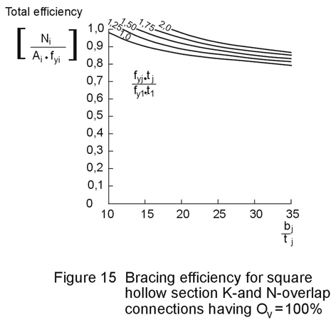
For 100% overlap joints of square hollow sections, the total efficiency is given by the curves in Figure 15. This efficiency can be achieved since the joint resistance is only dependent on the effective width failure criterion of the bracing.
For joints of rectangular hollow sections, however, too many failure criteria have to be checked in order to establish simple design charts. For designing these joints, it is possible to use the design charts for square hollow section joints to get the first indications.
A series of design charts for T, Y, X, K-gap, N-gap, K-partial overlap, N-partial overlap, K-100% overlap and N-100% overlap joints of square hollow sections is shown in [8].
The design procedure for the design of lattice girders is given in Lecture 13.1.
[1] Eurocode 3: "Design of Steel Structures": ENV 1993-1-1: Part 1.1: General Rules and Rules for Buildings, CEN, 1992.
[2] Eurocode 3: ENV 1993-1-1: Annex K: Hollow Section Lattice Girder Connections, CEN, 1992.
[3] Wardenier, J.: Hollow section joints, ISBN 90-6275-084-2, Delft University Press, Delft, 1982.
[4] Wardenier, J., Giddings, T.W.: The strength and behaviour of statically loaded welded connections in structural hollow sections, CIDECT Monograph No.6, 1986
[5] Wardenier, J., Stark, J.W.B.: The static strength of welded lattice girder joints in structural, hollow sections, ECSC Report EUR 6428C MF 1980.
[6] Packer, J. A. and Henderson, J. E.: Design guide for hollow structural section connections, Canadian Institute of Steel Construction, 1992.
[7] Packer, J. A.: Theoretical behaviour and analysis of welded steel joints with RHS chords, CIDECT, Final Report 5U-78/19.
[8] Packer, J.A., Wardenier, J., Kurobane, Y., Dutta, D., Yeomans, N.: Design guide for rectangular hollow section (RHS) joints under predominantly static loading, edited by CIDECT, Verlag TÜV Rheinland.
|
TYPE OF JOINT |
DESIGN RESISTANCE (i = 1,2) |
|
T-, Y- and X- joints |
CHORD FACE YIELDING b £ 0,85 |
|
|
|
|
K- and N- gap joints |
CHORD FACE YIELDING b £ 1,00 |
|
|
|
Table 1 Design resistance of welded joints between square or circular bracing members and a square chord section
|
K- and N- overlap joints*) |
EFFECTIVE WIDTH 25% £ l ov £ 50% |
|
|
|
|
EFFECTIVE WIDTH 50% < l ov < 80% |
|
|
|
|
|
EFFECTIVE WIDTH l ov ³ 80% |
|
|
|
|
|
Circular bracings |
multiply given formulae by p /4 and replace bi and hi by di |
Table 1 Continued
|
FUNCTIONS |
|
|
kn = 1,0 for n ³ 0 (tension) kn = 1,3 + but kn £ 1,0 n = s o /fyo |
|
|
beff = but beff £ bi |
be,ov = but be.ov £ bi |
|
*) Only the overlapping bracing is to be checked. The bracing member efficiency (i.e. the design resistance of the joint divided by the plastic design resistance of the cross-section of the bracing member) for the overlapped brace is not to be taken higher than that of the overlapping bracing. |
|
Table 1 Continued
|
Type of joint |
Joint parameters [i = 1 or 2; j = overlapped brace] |
|||||
|
bi/bo di/bo |
bi/ti di/ti |
bo/to |
(b1 + b2)/2bi bi/bj ti/tj |
Gap or overlap |
||
|
Compression |
Tension |
|||||
|
T-, Y- or X- |
bi/bo ³ 0,25 but £ 0,85 |
bi/ti £ 1,25ÖE/fyi and bi/ti £ 35 |
bi/ti £ 35 |
bo/to ³ 10 but £ 35 |
||
|
K - gap N - gap |
bi/bo ³ 0,35 and ³ 0,1 + 0,01bo/to |
bo/to ³ 15 but £ 35 |
(b1+b2)/2b1 ³ 0,6 but £ 1,3 |
g/bo ³ 0,5 (1-b ) but £ 1,5 (1-b ) g ³ t1 + t2 |
||
|
K - overlap N - overlap |
bi/bo ³ 0,25 |
bi/ti £ 1,10ÖE/fyi |
bo/to £ 40 |
ti/tj £ 1,0 bi/bj ³ 0,75 |
l ov ³ 25%but £ 100% |
|
|
Circular bracing member |
di/bo ³ 0,40 but £ 0,8 |
di/ti £ 1,50 ÖE/fyi |
di/ti £ 50 |
As above but with di replacing bi |
||
|
q ³ 30° |
||||||
|
*) Outside these parameter ranges the resistance of the joint may be determined as for a joint with a rectangular chord section |
||||||
Table 2 Range of validity for Table 1
|
TYPE OF JOINT |
DESIGN RESISTANCE (i = 1,2) |
|
|
|
CHORD FACE YIELDING b £ 0,85 |
|
|
|
||
|
CHORD SIDE WALL BUCKLING1) b = 1,0 |
0,85 £ b £ 1,0 linear interpolation of chord face yielding and chord side wall criteria |
|
|
|
||
|
EFFECTIVE WIDTH b ³ 0,85 |
||
|
PUNCHING SHEAR 0,85 £ b £ 1 - 1/g |
||
|
|
||
Table 3 Design resistance of welded joints of rectangular, square or circular bracing members and a rectangular or square chord section
|
K- and N- gap joints |
CHORD FACE YIELDING |
|
|
|
|
CHORD SHEAR |
|
|
|
|
|
EFFECTIVE WIDTH |
|
|
|
|
|
PUNCHING SHEAR b £ 1 - 1/g |
|
|
|
|
|
K- and N- overlap joints |
SIMILAR TO JOINTS OF SQUARE HOLLOW SECTIONS (TABLE 1) |
|
Circular braces |
multiply given formulae with p /4 and replace bi and hi by di |
Table 3 Continued
|
FUNCTIONS |
|
|
tension: fk = fyo compression: fk = c .fyo (T- and Y-joints) fk = 0,8 c fyo sin q 1 (X-joints) c = f() use buckling curve a with: |
kn = 1,0 for n ³ 0 (tension) kn = 1,3 + but kn £ 1,0 |
|
Av = (2 ho + a bo) to for rectangular brace: a = for circular brace: a = 0 |
|
|
beff = but beff £ bi |
bep = but bep £ bi |
|
1) For X-joints with angles q < 90° the chord side walls must be checked for shear |
|
Table 3 Continued
|
Type of joint |
Joint parameters [i = 1 or 2; j = overlapped brace] |
|||||
|
bi /bo hi /bo |
bi /ti hi /ti di /to |
hi/bi |
bo /to ho /to |
Gap or overlap bi/bj ti /tj |
||
|
Compression |
Tension |
|||||
|
T-, Y- or X- |
³ 0,25 |
£ 1,25£ 35 |
£ 35 |
hi /bi ³ 0,5 but £ 2,0 |
£ 35 |
|
|
K - gap N - gap |
b ³ 0,35and ³ 0,1 + 0,01 bo /to |
£ 35 |
g/bo ³ 0,5 (1-b ) but £ 1,5 (1-b ) g ³ t1 + t2 |
|||
|
K - overlap N - overlap |
bi /bo ³ 0,25 |
£ 1,10 |
£ 40 |
l ov ³ 25%but £ 100% ti /tj £ 1,0 bi /bj ³ 0,75 |
||
|
Circular bracing member |
di /bo ³ 0,40 but £ 0,8 |
£ 1,50 |
£ 50 |
As above but with di replacing bi |
||
|
q ³ 30° |
||||||
Table 4 Range of validity for Table 3
|
TYPE OF JOINT |
DESIGN AXIAL RESISTANCE Ni.Rd |
DESIGN IN PLANE MOMENT RESISTANCE Mip.Rd |
|
|
EFFECTIVE WIDTH General check |
- |
|
fy1 t1 beff |
||
|
CHORD SIDE WALL BEARING only when b1 ³ bo - 2to |
- |
|
|
fyo to (2 t1 + 10to) |
||
|
PUNCHING SHEAR Only when b1 £ bo - 2 to |
- |
|
|
0,58 fyo to (2t1 + 2bep) |
||
|
Range of validity see Table 4 except 0,5 £ b £ 1,0; bo /to £ 30 Special functions see Table 3 |
||
Table 5 Design resistance of welded joints with gusset plates or sections
|
TYPE OF JOINT |
DESIGN RESISTANCE (i = 1,2) |
|
T- and X- Joints under in-plane bending q = ~ 90°
|
CHORD FACE YIELDING b £ 0,85 |
|
|
|
|
CHORD SIDE WALL BEARING 0,85 £ b £ 1,0 |
|
|
fk = 0,8 fyo For X-Joints |
|
|
EFFECTIVE WIDTH 0,85 £ b £ 1,00 |
|
|
|
|
|
T- and X- Joints under out-of-plane bending q = 90°
|
CHORD SIDE WALL BEARING 0,85 £ b £ 1,00 |
|
fk = 0,8 fyo For X-Joints |
|
|
EFFECTIVE WIDTH 0,85 £ b £ 1,00 |
|
|
|
Table 6 Design resistance of welded joints between rectangular hollow sections loaded by bending moments
|
TYPE OF JOINT |
CORRECTION FACTOR TO UNIPLANAR JOINTS |
|
60 ° £ y £ 90° TT-Joint |
0,9 |
|
60 ° £ y £ 90° |
0,9 in addition: check design resistance of cross-section 1-1 (gap joints only)
|
|
Range of validity see Table 4 |
|
Table 7 Correction factors for multi-planar joints


 Also: general interaction between V = Ni sin q i and No,Rd


 fk = fyo For T-Joints
 fk = fyo For T joints