ESDEP WG 12
FATIGUE
To give information for the design of hollow section joints with guidelines for an optimal design.
Lecture 12.1: Basic Introduction to Fatigue
Lecture 12.3: Effect of Workmanship on Fatigue Strength of Longitudinal and Transverse Welds
Lecture 13.1: Application of Hollow Sections in Steel Structures
Lecture 13.2: The Behaviour and Design of Welded Connections Between Circular Hollow Sections under Predominantly Static Loading
Lecture 13.3: The Behaviour and Design of Welded Connections Between Rectangular Hollow Sections under Predominantly Static Loading
Lecture 12.4.1:Fatigue Behaviour of Hollow Section Joints I
The geometric stress concept and the classification method used for the fatigue design of hollow section joints are discussed in more detail and illustrated by design examples. Guidelines and simplified design graphs are given to give insight into the stress concentration factors to stimulate optimal design.
The limitations and the validity of various approaches are also discussed.
The notation of Eurocode 3 has been adopted.
In Lecture 12.4.1, the fatigue behaviour of hollow section joints and methods of analyses are discussed. In Eurocode 3, two methods are adopted for the design of hollow section joints [1].
The geometric stress method (sometimes called the hot spot stress method) can generally be used for all types of connections between hollow sections. However, sufficient data regarding stress concentration factors for various types of joints and loadings are required.
The classification method also given in Eurocode 3 for K- and N-type joints with wall thicknesses up to 12,5 mm is a simplified method, only valid for a particular range of geometrical parameters.
In this lecture these two methods are discussed in more detail and the method of design is given.
For fatigue design, the stress ranges in the members have to be known. The stresses determined depend directly on the idealization of the structure.
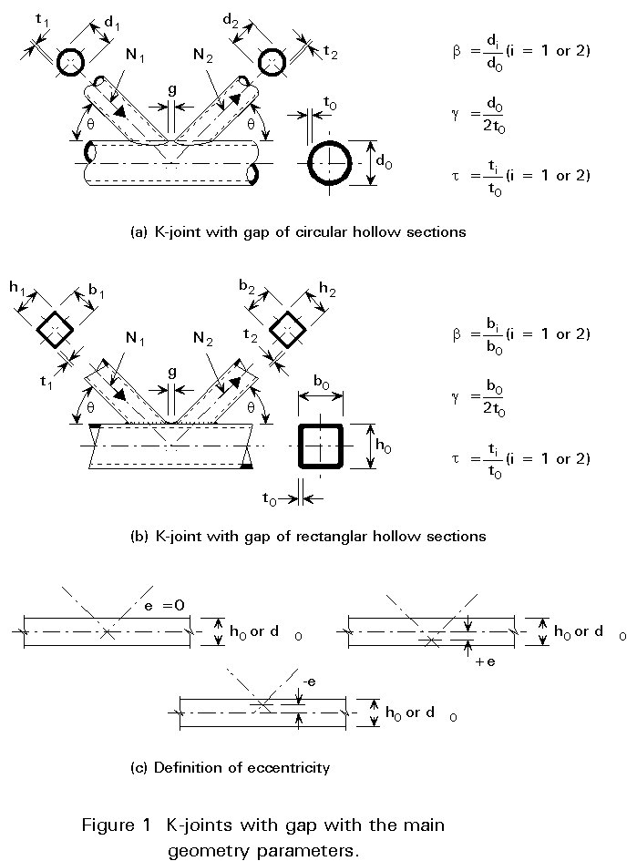
Trusses made of hollow sections generally have welded connections with continuous chords. For ease of fabrication the diagonals are sometimes connected with a certain noding eccentricity e, see Figure 1.
To obtain the correct load and stress distribution in the members, there are various methods of modelling [2].
a. The best method is to model the connections as substructures, as shown in Fig. 11 of Lecture 12.4.1. In this way, the influence of the geometry of the connections is directly taken into account. Even the governing extrapolated geometric stresses at the weld toes can be determined directly. However, this method requires excellent pre- and post-processors for the finite element modelling and sufficient computer capacity. Only specialized research institutes and companies can handle this method at present. Furthermore, the designer who is modelling should be a specialist in the use of the correct elements and the correct meshes.
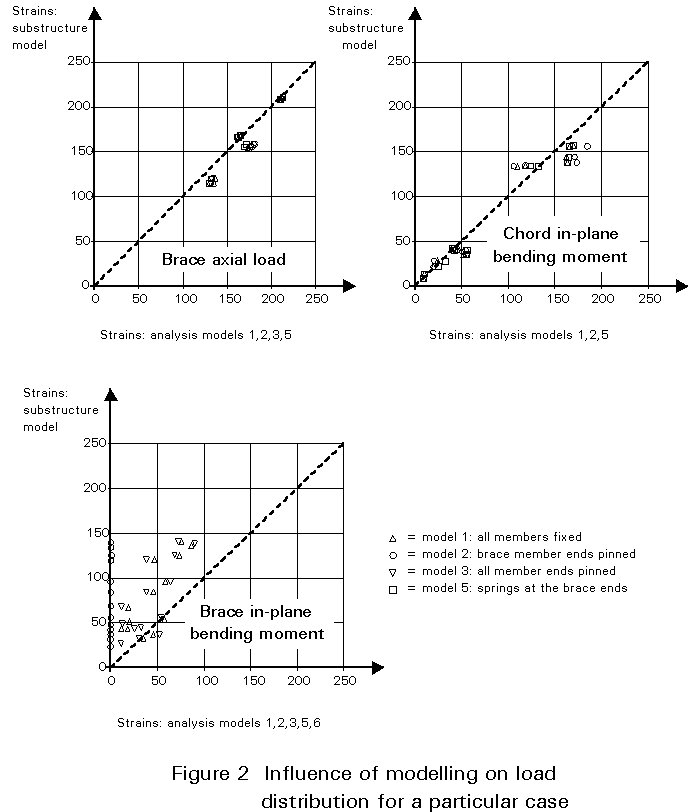
b. Another method is to use parametric formulae to determine the connection stiffness. The truss is then modelled with continuous chords and the diagonals are connected by springs representing the connection stiffness to the chord. Eccentricities should be incorporated in the model. In this way the proper bending moments in the members can be determined. The axial load distribution in the members is hardly influenced by the modelling, e.g. pin, spring or rigidly connected diagonals, see Figure 2. For bending moments, however, considerable differences may occur, since the actual bending stiffness is influenced by the axial loads present (interaction). In offshore engineering it is common practice to assume rigidly connected members. However, the value of the bending moments is reduced by taking not the moments at the noding points but those at the chord face. Due to a lack of evidence of the stiffness characteristics and for simplicity this simplification is used.
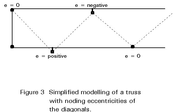
c. The simplest method of modelling is to use continuous chords with the diagonals connected with pins to the chord. Eccentricities exceeding 0,55 (do or ho) £ e £ 0,25 (do or ho) should be incorporated as shown in Figure 3.
The effect of secondary bending moments should be included by multiplying the stress ranges due to axial forces by the factors given in Tables 1a and 1b of Lecture 12.4.1.
This simplified modelling assumes indirectly that the stress concentration factors for bending are similar as those for axial forces, which is not generally valid. The stress concentration factors for bending in-plane are generally lower than those for axial force.
There are of course other methods of modelling, but those mentioned above represent the most commonly used ones.
End-to-end connections and connections with plates and hollow sections with attachments are classified in the normal way, i.e. a fatigue class is given for 2 ´ 106 cycles as shown in Table 1. Here a slope constant of m = 3 is adopted for N £ 5 ´ 106. For spectrum loading, a slope constant of m = 5 is adopted for 5 ´ 106 to the cut off limit 108. It should be noticed that for end-to-end connections an opposite "thickness effect" is included. In these connections no or only small geometrical effects are present, causing the crack to initiate from the root of the weld. Since these welds are made from one side (not counter welded) the root effect is more severe for smaller thicknesses. Here the limit is taken at 8 mm. For thicknesses larger than 25 mm the normal thickness effect should be applied, i.e.
Dst = Dst=25[t/25]-0,25 (1)
The basic reference curves for 16 mm wall thickness, according to Eurocode 3 [1] are given in Figure 4. The equations for the reference curves and the thickness effects to be adopted are also given.
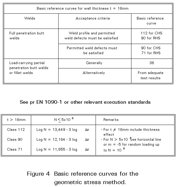
As discussed in Lecture 12.4.1, for hollow section joints with partial penetration welds or fillet welds, sufficient evidence is now available to use the same curves as for full penetration butt welds.
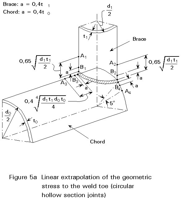
The geometric stress should be determined by extrapolation of the geometric stress outside the influence region of the weld to the weld toe. For most connections of circular hollow sections the geometric stress has a linear part and a linear extrapolation can be used as shown in Figure 5a.
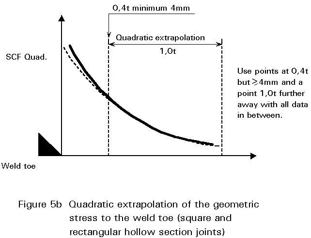
For square or rectangular hollow section joints the geometric stress is non-linear and a quadratic extrapolation gives a better accuracy and lower scatter in test results, Figure 5b. This extrapolation is more consistent with the mode of failure (location of the crack).
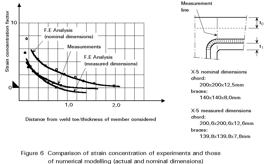
Determination of the geometric stresses by F.E. modelling requires proper modelling (type of elements, mesh), preferably by methods which have been calibrated by tests [2]. Due to the difference between actual dimensions and nominal dimensions, the calibration should be done with care using the actual dimensions, see Figure 6.
The geometric stress can also be obtained by multiplying the nominal stresses by the relevant stress concentration factors. Many parametric formulae are now available for circular hollow section joints. The most extensive set which gives good agreement with measurements is given by Efthymiou [3]. For square hollow section joints, a set of parametric formulae for T- and X-joints is given by Van Wingerde [4]. For K- and N-joints of square hollow sections, formulae are available, however only for a particular combination of axial loads and bending moments [5]. Thus, they are not generally applicable. Currently, new parametric formulae are being developed in the framework of a CIDECT programme. These formulae will become available in 1994.
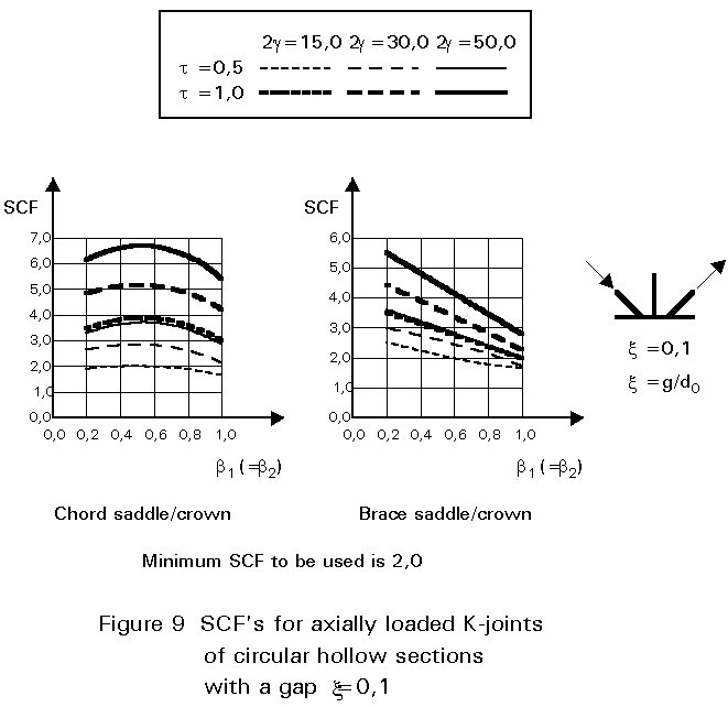
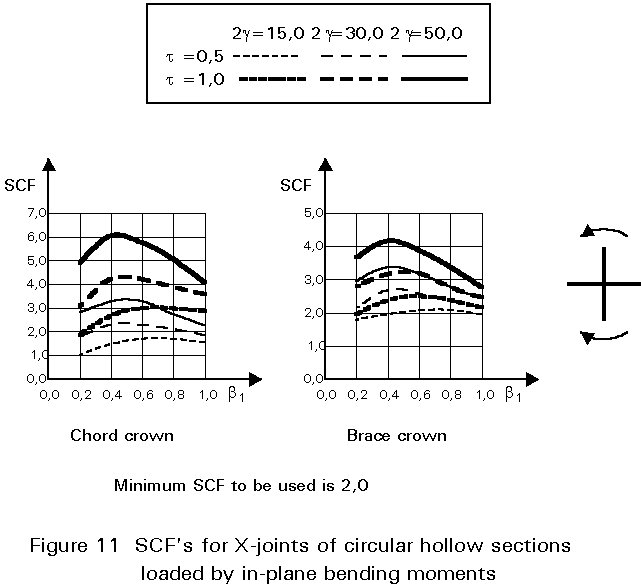
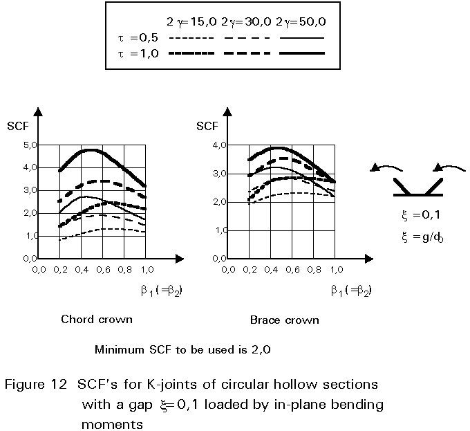
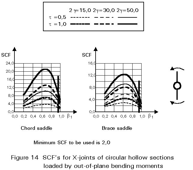
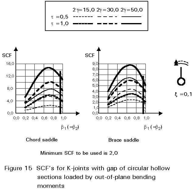
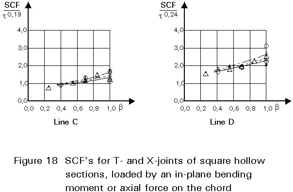
To give formulae for all types of joints, for various locations and for various loadings is beyond the scope of this lecture. However, some graphical presentations are given in Figures 7 - 15 for circular hollow section joints and in Figures 16 - 18 for T- and X-joints of square hollow sections. If the effect of the stiffness distribution along the intersection perimeter is clearly understood, then the tendency of the graphs will be clear. All graphs show that the SCF for the saddle location achieves a maximum for medium ß ratios. For T- and X-joints minimum values are obtained for ß = 1,0. Here, the SCF changes very rapidly for small variations of ß. For this reason, for X-joints of circular hollow sections, lower values than those for ß = 0,95 are not taken, because for ß= 1,0 the weld might cause an eccentricity.
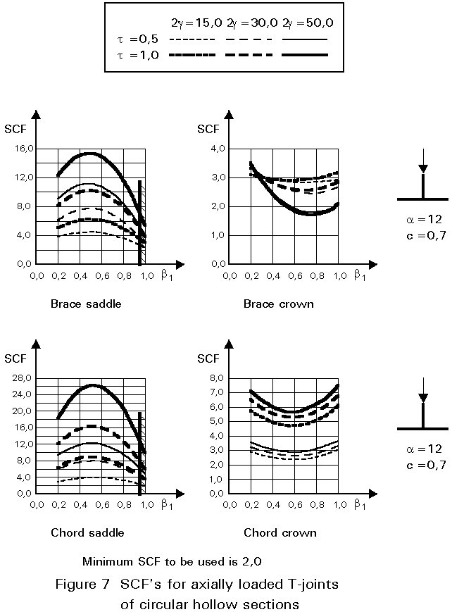
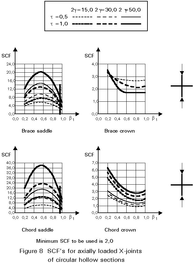
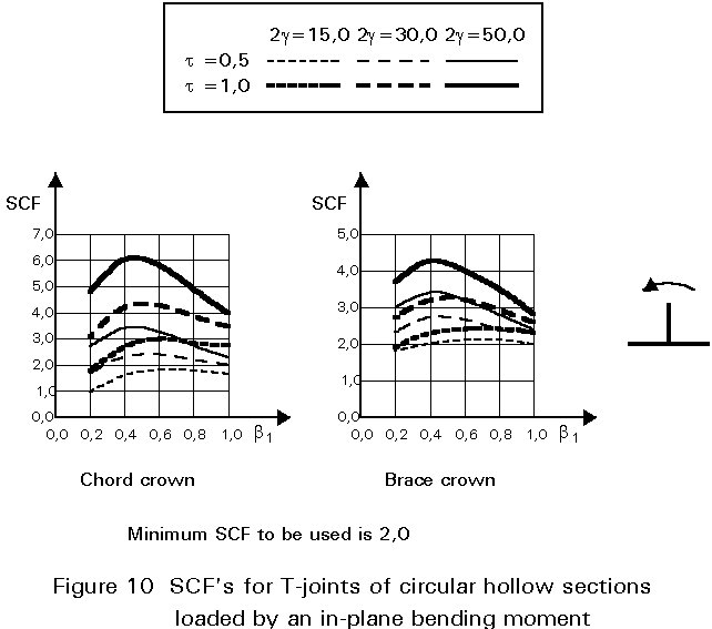
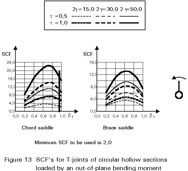
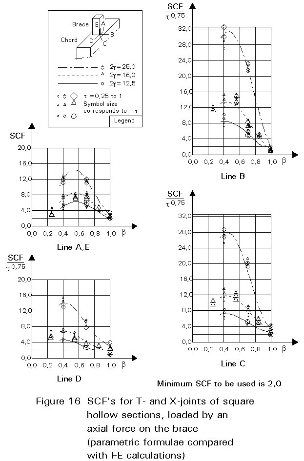
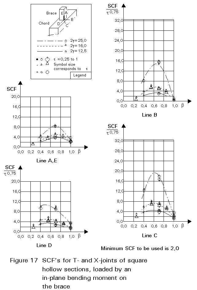
Note that the effect of the bending moment in the chord in a T-joint is included in the SCF's for T-joints of circular hollow sections, whereas for T-joints of square hollow sections it has been excluded, allowing the same presentation as for X-joints.
It is recommended that a minimum stress concentration factor of 2 is adopted to cover cracking from the root of the weld. Furthermore, the SCF's should be multiplied by the following correction factors for square hollow section joints if fillet welded connections are used:
Brace: 1,4 (for lines A and E)
Chord: 1,0 (no correction factors)
These factors cover the effect of brace wall bending. For the chord, the weld toe is located further away from the brace, resulting in a lower SCF. However, insufficient evidence is available yet to quantify this in general. Therefore, a factor 1,0 is adopted for the time being.
For an optimal design the geometric stress concentration factors should be low, i.e. low t and g values and low ß or high ß values.
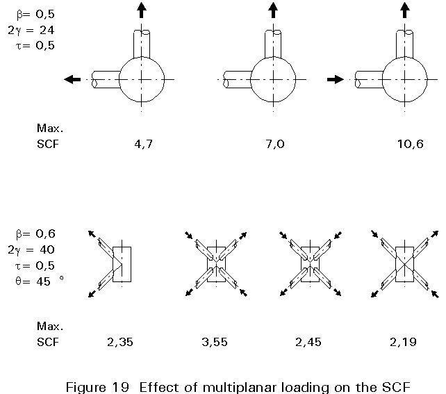
As indicated in Lecture 12.4.1, the geometric stress range can be obtained by multiplying the relevant stress concentration factor (location and loading) by the nominal stress range, which causes the stress peak.
Care has to be taken that the stress concentration factors are only used within the range of validity. Figure 19 shows, for example, that the effect of multiplanar loading can be considerable.
The fatigue life is determined by checking the highest geometric stress for the chord as well as for the brace multiplied by the appropriate gM factor with the basic Ds-N curve using the appropriate thickness.
The classification method is only used for axially loaded K- and N-type joints of circular and rectangular hollow sections, since the variation in SCF is too large for other types of joints.
In principle, the classes should be a lower bound, defined by the basic reference curve for the geometric stress range divided by the SCF's which can be obtained within the range of validity. The classification is based on an analysis of relevant test results, taking account of the parameter t and using a lower bound. In this approach, the effects of other influencing parameters and the thickness effects are combined to some extent.
Multiplication of the class by a minimum SCF of 2,0 gives values far exceeding those of the basic reference curve for geometric stress, even if the thickness effect is incorporated. On the other hand, the two approaches cannot be compared directly, since the slopes are different, i.e. for the classification method a fixed slope constant of m = 5 is adopted.
Although Eurocode 3 [1] gives the range of validity shown in Table 1, it would be better to change some of the limits, i.e.
4 £ to or t1 £ 8 mm instead of to or t1 £ 12,5 mm
bo/to × t1 or do/to × t1 £ 100 instead of bo/to or do/to £ 25
These limits are in better agreement with the test results on which this classification method has been based.
In view of these comments, one could ask: "Why has the classification method been adopted?" At the time of drafting Eurocode 3, insufficient evidence was available for SCF's of hollow section joints. Further, many designers are not familiar with the geometric stress concept. Therefore the classification method was favoured by many countries.
The design is very simple, since the designer determines the nominal stress ranges in the brace with one of the methods described in Section 2 considering the factors for secondary bending moments and the relevant gM factor. The design class gives the Ds-N curve and the fatigue life can be determined.
The connections at the welded joints should be made over the entire perimeter of the hollow sections by means of a full penetration weld, partial penetration weld, fillet weld, or a combination. Full penetration welds should be used if:
Attention should be paid to the proper selection of materials and the welding procedure. To avoid failure of the weld under static loading, the throat thickness of the fillet weld for steel up to S355 is equal to or greater than the wall thickness of the brace (a ³ t1).
Welding should start at the middle of the sides. If welding of joints commences at the corners of the brace, the fatigue strength deteriorates. This may result in a decrease by a factor 2 on stress range.
For the geometric stress method and the classification method:
[1] Eurocode 3: "Design of Steel Structures": ENV 1993-1-1: Part 1, General rules and rules for buildings, CEN, 1992.
[2] Romeijn, A., Puthli, R.S., Wardenier, J.: "Finite element modelling of multiplanar joint flexibility in tubular structures", Proceedings ISOPE '92, San Francisco, U.S.A.
[3] Efthymiou, M.: "Development of SCF formulae and generalised influence functions for use in fatigue analysis", Offshore Tubular Joints Conference (OTJ '88), UEG Offshore Research, Englefield Green Near Egham, U.K., 1988.
[4] Van Wingerde, A.M.: "The fatigue behaviour of T- and X-joints made of square hollow sections", Ph.D. thesis, Delft University of Technology.
[5] Mang, F., Herion, S., Bucak, Ö., Dutta, D.: "Fatigue behaviour of K-joints with gap and with overlap made of rectangular hollow sections", p. 297-310 of Proceedings "Tubular Structures", edited by E. Niemi and P. Mäkeläinen.
Table 1 Detail category: Hollow sections and simple connections
|
Details loaded by nominal normal stresses |
||
|
Detail category m = 3 |
Constructional detail |
Description |
|
160 |
See Fig T1-1
|
Rolled and extruded products Non-welded elements. Sharp edges and surface flaws to be improved by grinding |
|
140 |
See Fig T1-2
|
Continuous longitudinal welds Automatic longitudinal welds with no stop-start positions; proven free of detectable discontinuities |
|
71 |
See Fig T1-3
|
Transverse butt welds Butt welded end-to-end connection of circular hollow sections Requirements - Height of the weld reinforcement less than 10% of weld width; smooth transitions to the flat surface - Welds made in flat position and proven free of detectable discontinuities - Details with wall thicknesses greater than 8 mm may be classified two detail categories higher, i.e. > 90 |
|
56 |
See Fig T1-4
|
Transverse butt welds Butt welded end-to-end connection of rectangular hollow sections Requirements - Height of the weld reinforcement less than 10% of weld width; smooth transitions to the flat surface - Welds made in flat position and proven free of detectable discontinuities - Details with wall thicknesses greater than 8 mm may be classified two detail categories higher, i.e. > 71 |
|
71 |
See Fig T1-5
|
Welded attachments (non load-carrying welds) Circular or rectangular section, fillet welded to another section. Section width parallel to stress direction £ 100 mm |
|
50 |
See Fig T1-6
|
Welded connections (load-carrying welds) Circular hollow sections, end-to-end butt welded with an intermediate plate Requirements - Welds proven free of detectable discontinuities - Details with wall thicknesses greater than 8 mm may be classified one detail category higher, i.e > 56 |
|
45 |
See Fig T1-7
|
Welded connections (load-carrying welds) Rectangular hollow sections, end-to-end butt welded with an intermediate plate Requirements - Welds proven free of detectable discontinuities - Details with wall thicknesses greater than 8 mm may be classified one detail category higher, i.e. > 50 |
![]()
![]()
![]()
![]()
![]()
Table 1 (continued) Hollow sections and simple connections
|
Details loaded by nominal normal stress (continued) |
|||
|
Detail category m = 3 |
Constructional detail |
Description |
|
|
40 |
See Fig T1-8
|
Welded connections (load-carrying welds) Circular hollow sections, end-to-end fillet welded with an intermediate plate Requirements - Wall thickness less than 8 mm |
|
|
36 |
See Fig T1-9
|
Welded connections (load-carrying welds) Rectangular hollow sections, end-to-end fillet welded with an intermediate plate Requirements - Wall thickness less than 8 mm |
|
|
80 |
l £ 50 mm |
See Fig T1-10
|
Longitudinal attachments (non-load-carrying welds) The detail category varies according to the length of the attachment l |
|
71 |
50 < l £ 100 mm |
||
|
50 |
l > 100 mm |
||
|
80 |
t £ 12 mm |
See Fig T1-11
|
Transverse attachments The end of the weld more than 10 mm from the edge of the plate |
|
71 |
t > 12 mm |
||
|
80 |
t £ 12 mm |
See Fig T1-12
|
Transverse attachments Diaphragms of rectangular girders welded to the flange or web |
|
71 |
t > 12 mm |
||
|
80 |
See Fig T1-13 |
Transverse attachments The effect of welded shear connectors on base material |
|
|
71 |
See Fig T1-14
|
Cruciform joints (load-carrying welds) Full penetration weld, inspected free of detectable discontinuities Requirements - The maximum misalignment of the load-carrying plates should be less than 15% of the thickness of the intermediate plate |
|
|
36 |
See Fig T1-15
|
Cruciform joints (load-carrying welds) Fillet welded connection. Two fatigue assessments are required Firstly root cracking is evaluated by determining the stress range in the weld throat area, Category 36 Secondly toe cracking is evaluated by determining the stress range in the load-carrying plates, Category 71 Requirements - The maximum misalignment of the load-carrying plates should be less than 15% of the thickness of the intermediate plate |
|
|
50 |
t and tc £ 20 mm |
See Fig T1-16
|
Cover plates (load-carrying welds) End zones of single or multiple welded cover plates, with or without frontal weld. When the reinforcing plate is wider than the flange a frontal weld, carefully ground to remove undercut, is necessary |
|
36 |
t and tc £ 20 mm |
||

Table 2: Classes for classification method
|
Detail categories for lattice girder joints |
|||
|
Detail category m = 5 |
Construction Details |
Description |
|
|
90 |
to/ti ³ 2,0 |
See Fig T2-1 |
Joints with gap Circular hollow sections, K and N joints |
|
45 |
to/ti ³ 1,0 |
||
|
71 |
to/ti ³ 2,0 |
See Fig T2-2 |
Joints with gap Rectangular hollow sections, K and N joints Requirements × 0,5(bo-bi) £ g £ 1,1(bo-bi) × g ³ 2to |
|
36 |
to/ti ³ 1,0 |
||
|
71 |
to/ti ³ 1,4 |
See Fig T2-3 |
Joints with overlap K joints Requirements × overlap between 30% and 100% |
|
56 |
to/ti ³ 1,0 |
||
|
71 |
to/ti ³ 1,4 |
See Fig T2-4 |
Joints with overlap N joints |
|
50 |
to/ti ³ 1,0 |
||
|
General Requirements to, ti £ 12,5 mm 35° £ Q £ 50° bo/to £ 25 0,4 £ bi/bo £ 1,0 0,25 £ di/do £ 1,0 bo/to £ 25 bo £ 200 mm do £ 300 mm -0,5do £ e £ 0,25do -0,5ho £ e £ 0,25ho Out-of-plane eccentricity: £ 0,02bo or £ 0,02do Fillet welds are permitted in braces with wall thicknesses £ 8 mm |
|||
Table 2: Classes for classification method
Note regarding General Requirements:
Preferably use 4 £ to or t1 £ 8 mm instead of £ 12,5 mm
Preferably use bo/to × t1 or do/to × t1 £ 100 mm instead of bo/to or do/to £ 25