
ESDEP WG 12
FATIGUE
Identification of factors influencing the fatigue strength of welded joints and of the consequences for design, fabrication and inspection.
Lecture 12.1: Basic Introduction to Fatigue
Lecture 12.6: Fatigue Behaviour of Bolted Connections
Lecture 3.4: Welding Processes
Lecture 3.6: Inspection/QA Assurance
The data on fatigue strength given in Eurocode 3 [1] are briefly reviewed. The strengths of longitudinal and transverse welds are related to the quality of workmanship. The need for inspection and the limitations of non-destructive testing are examined. The implications for economic design, detailing and specification are set out.
Any joint in a structure or in any part of it is a potential point of weakness, both in static strength and in fatigue.
For fatigue the potential weakness is evident from the fatigue strength data given in Eurocode 3 [1] (Figure 1). There the perfect plate is in detail category 160, which is the fatigue strength at 2.106 cycles, whilst the joint detail with the worst geometry and hence stress concentration, is in category 36.
In a welded joint potential sites for initiation of a fatigue crack are:
(i) the end of the weld
(ii) a weld toe
(iii) a change of direction of the weld.
(i) the weld root
(ii) the weld surface
(iii) an internal flaw.
Even one type of joint, the longitudinal fillet or butt weld, can fall into any one of four categories, from 140 to 100, depending on workmanship, see Figure 2.
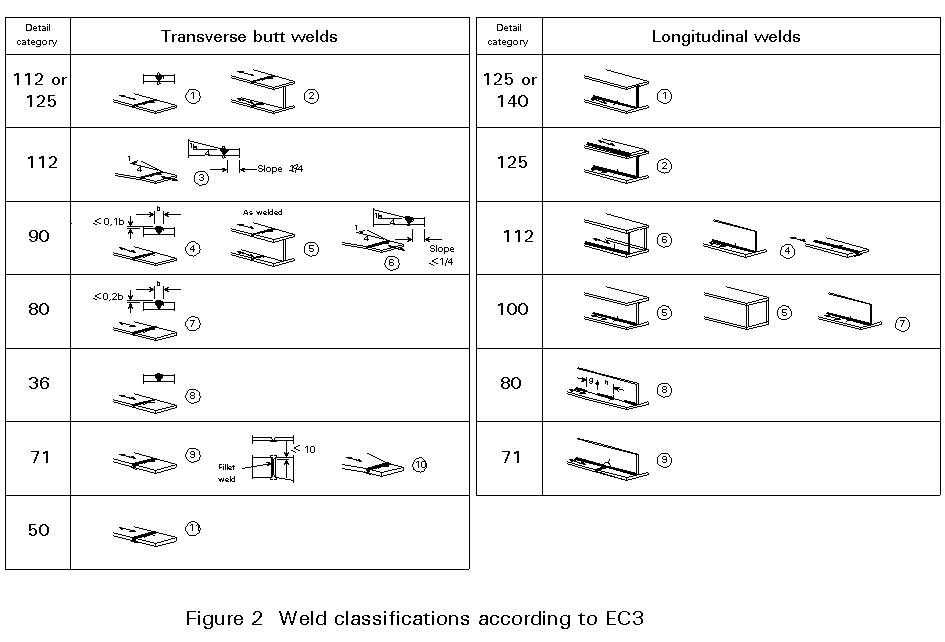
Transverse butt welds can have an even wider range of strengths (Figure 2) - from category 125 to category 36, 7 categories in all. If one excludes butt welds made from one side only, with and without backing strips, i.e. detail categories 71, 50 and 36, four categories are left for "good" butt welds. Here the category depends on both weld geometry and workmanship.
Other welds (transverse fillets, welds to attachments, etc.) also show wide variations in strength depending on geometry and workmanship.
It is important to note that a number of other (usually accidental) results of poor workmanship can reduce the performance of a detail to below what its category would indicate:
(a) weld spatter
(b) accidental arc strikes
(c) unauthorised attachments
(d) corrosion pitting
(e) weld flaws, particularly in transverse butt welds
(f) poor fit-up
(g) eccentricity and misalignment.
Most of these are largely unquantifiable and must be controlled by adequate inspection and repair.
It is the purpose of this lecture to describe in greater detail welded joints and the matters to be considered by the designer before deciding the fatigue strength that will be used in calculations.
The highest category for longitudinal welds, 140, applies only where there are "no significant flaws". This implies automatic welding, no stop/start positions, no slag inclusions or blow holes - near perfection "demonstrated by specialist inspection".
The next category down, 125, requires automatic welding and expert repair, followed by inspection, of any accidental stop/start positions. Leaving stop/start positions brings the category of longitudinal fillet welds down to 112 and that of longitudinal butt welds down to 100.
Manual fillet or butt welds and one-sided butt welds are all in category 100, as are "repaired" welds.
There is experimental evidence that small slag inclusions can bring the strength of a longitudinal fillet weld down to category 90.
A lower limit to the strength of defective longitudinal fillet welds is probably that of an intermittent weld, category 80, or even the end of such a weld at a cope hole, category 71.
Transverse butt welds can reach category 125 when "high quality welding" is obtained and proved to have been achieved by later inspection. Amongst other requirements, the proposed welding standard limits solid inclusions in such welds to a width of 2mm and a length of 6mm, thus acknowledging the importance of internal defects.
Lower quality welds fall into category 112 provided the welds are ground flush. Otherwise they are in category 90, or 80 for splices in rolled sections or girders. Here the category depends on the weld profile and the likely quality of workmanship; internal defects are not mentioned.
In fact, internal defects have at least as great an influence on the fatigue strength of transverse butt welds as does the weld profile.
Another factor which affects the strength of splices in girders, and which is not mentioned explicitly in the description of the detail categories, is the order in which the welds are made. This can affect the level of residual stress.
The test results shown in Figure 3 illustrate these points. They are all results of tests on transverse butt welds shown against the grid of lines representing the fatigue strengths given in Eurocode 3 [1] for the various detail categories. The short thick lines represent test results on small plate specimens, 40mm wide and 10mm thick. All other points represent results from tests of complete beams.
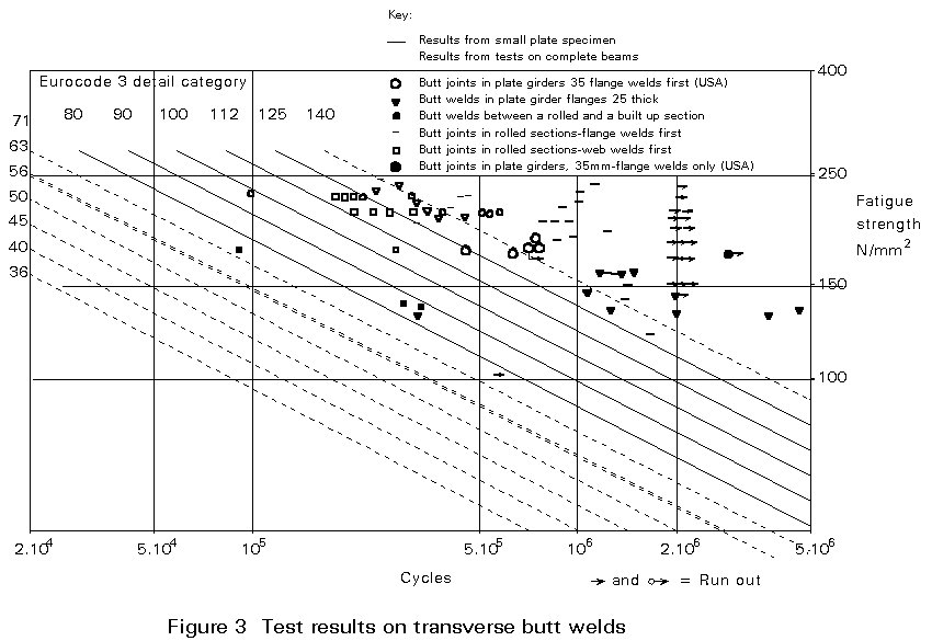
The results range from category 112 for the plate specimens down to category 63 or so for a butt joint in a rolled I beam.
The reasons for this spread of results are partly weld quality and partly residual stresses caused by different welding procedures.
It is likely that the plate specimens were reasonably free from internal defects. The butt welds in the plate girder flanges, shown as large circles, contained various small defects, in the range of 3mm2 to 30mm2 from which the cracks leading to failure originated. Allowing for the fact that the plate girder flanges were 35mm thick, all results would fit into category 112. So would the results from tests on small girders with 25mm thick flanges, shown as triangles.
The results shown as small dots were obtained for a butt weld between a rolled and a built-up I section. The failure was due to a large "lack of fusion" defect in the 30mm thick flange directly above the web to which it was joined by 24mm radii. The defect had an area of about 80mm2 and is sketched in Figure 4 and was attributed to faulty weld preparation. It must be pointed out, however, that it was the work of experienced fabricators, who clearly had not appreciated the difficulty of achieving full penetration at this point.

Even allowing for size effect, one would put this result into category 63. There is no information on the strength of such welds in Eurocode 3 - they should not be used. A British Standard, BS5400: Part 10 puts such welds in a class which corresponds, as regards strength, to category 63 [2]. This classification fits the test results.
These few test results suffice to indicate that internal weld defects occur and that they have a decisive influence on the fatigue strength of a welded joint.
To determine this effect quantitatively, a fracture mechanics study has been undertaken, based on fatigue test results from butt welds containing known defects. The results were used to obtain basic fracture mechanics data. These results showed the scatter typical of all fatigue test results. A lower bound of the values was then used to calculate the fatigue strength of butt welds of various thicknesses containing defects of various sizes. The defect size was expressed as an area; a reasonable approximation which avoided the need to give two dimensions for every defect and to investigate various shapes.
The figures shown in Figure 5 are approximate and were obtained by interpolation, and some extrapolation, from the results produced by the investigation.
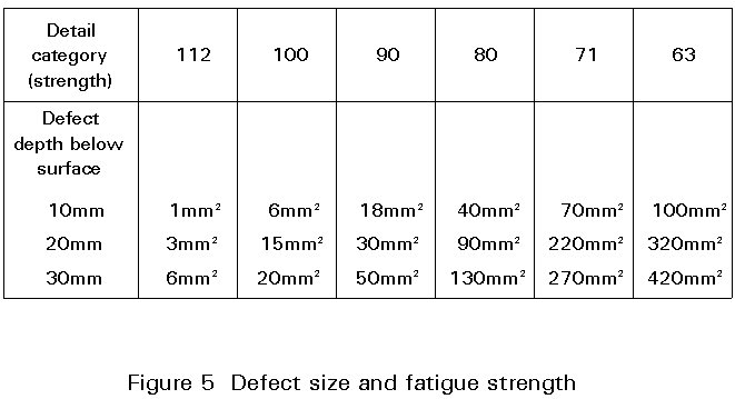
The agreement between these figures and the few large beam results is quite good.
It will be noted that near surface defects cause a greater loss of fatigue strength than deep ones and that a 12mm2 defect, such as suggested in the draft welding standard [1], would bring a butt weld strength down to category 100, or even 90 if near the surface.
It is clear, therefore, that high fatigue strength in a butt weld requires nearly perfect welds.
The results in Figure 3 showing the effect of different welding procedures and, hence, residual stress are the two groups of squares.
They were obtained from tests on butt joints through rolled I sections. The higher set, full squares, were from specimens in which the flange butt welds were made before the web butt welds. The lower set, open squares, were obtained from specimens in which the reverse procedure had been used - web butt weld first, then flange butt welds so that their contraction was resisted by the web.
One set fits category 100, the other category 80 - a considerable loss of strength through using the wrong weld sequence.
These results do not stand alone; similar ones have been obtained in the United States and they are confirmed by the results shown by the circles on the figure.
These results were obtained from plate girder specimens with 35mm thick flanges. The full circles show results from specimens in which only the flange plates were butt welded, and that before they were welded to the webs. Allowing for size effect, they fit category 112 or, possibly, 125. The open circles are results from butt welds right through similar plate girders. They are little, if any, worse than those shown by full circles.
However, the welding procedure, shown in Figure 6, was designed to minimise residual stresses in the flange welds. Initially, the webs were not welded to the flange for some 110mm either side of the joint, the flange butt welds were made first, then the web butt weld and, finally, the web was welded to the flanges. This weld also served to close the small slot which had been left under the flange butt weld to allow radiography of these welds. Cope holes were neither needed nor provided.
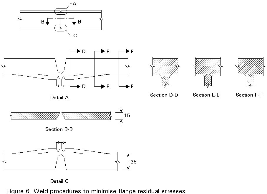
It is clear from these results that butt joints right through a girder can have the same fatigue strength as a butt weld through a plate provided that the right welding procedure is specified by the designer and followed in the fabrication shops. Otherwise there is a loss of fatigue strength of the order of 25%.
The results were obtained from tests on plate girders, but the conclusions have a wider application. They apply, for example, to joints in portal frames at or near the corners and any situation where there is a risk of high restraint of butt welds.
There is some evidence that similar considerations apply to welding attachments to girders. In one test, plates welded to the compression flange of a plate girder caused early cracks, as was expected. When similar attachments were welded to the flange plate before it was welded to the girder, no cracks were observed at about double the endurance; again an improvement of about 25% in the fatigue strength.
Given the effect welding procedure can have on the fatigue strength of a joint, it must be considered at the design stage and be specified; it cannot be left to the fabricator.
So far discussion has been limited to those types of weld (longitudinal butt and fillet welds, and transverse butt welds) whose fatigue strength can be very significantly affected by embedded, or usually more importantly, surface breaking defects. Many other types of weld can be and have been used which, even if carried out perfectly, result in a considerable loss of fatigue strength. This loss is normally a result of the welds forming geometrical discontinuities, or causing stress raisers; frequently workmanship faults, unless gross, have little further degrading effect.
Three specific types of weld will be considered in this section:
a. Transverse fillet welds
b. Welds connecting load-carrying and non load-carrying attachments.
It is sometimes difficult to differentiate between the reduction of strength which results from poor detailed design, and that which results from poor workmanship, since there can be a correlation between the two; however, the main considerations are described below.
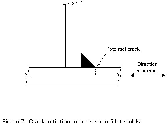
Transverse fillet welds may be used for connecting transverse stiffeners to a plate (e.g. web stiffeners, or transverse stiffeners on a wide flange plate in compression, or diaphragms in box girders); they always reduce the fatigue strength of the parent plate. Eurocode 3 Part 1 [1] shows that the best that can normally be achieved is category 80 if the thickness of the stiffener or diaphragm is 12 mm or less, or category 71 if it is more than 12 mm. As is discussed later, it may be desirable or possible in some circumstances to dispense with such stiffeners by thickening the parent plate.
As fatigue failure resulting from a transverse fillet weld is usually initiated by a crack growing into the parent plate from the toe of the weld (Figure 7), faults in the weld itself (e.g. slag inclusions or porosity) are unlikely to reduce the strength further. However, any faults in workmanship which damage the parent plate can be serious; in particular any residual faults which take the form of planar cracking in the heat affected zone of the plate must be strictly forbidden, and inspection must be specified to ensure that any such faults can be detected and rectified.
Undercut in the parent plate at the weld toe, if excessive, can also degrade the fatigue strength although a small amount can generally be tolerated without reducing the category below the figures given above. It is generally considered that undercut of not more than 0,5 mm is permissible, provide that the total undercut does not reduce the cross-section by more than 5%.
One area where design and workmanship tend to overlap is where a transverse fillet weld ends near the edge of the parent plate. For example, in the case of a web stiffener attached also to the flange of a joist, what happens to that portion attached near to the edge of the flange? Where the stiffener is terminated within 10 mm of the edge of the flange, the category is reduced to 50 at that point; where it is terminated 10 mm or more from the edge, the "full" category of 71 or 80 as appropriate may be used.
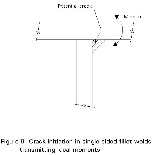
Other applications of transverse fillet welds where the workmanship can affect the strength arise where the weld is subject to bending about its longitudinal axis; such conditions can arise where the traffic loads on a steel deck plate of a bridge are transferred to stiffeners or girders through fillet welds between the plate and the stiffener web (Figure 8). In this case the quality of the weld is all important; in particular the fit-up between the plate and the web should be very good otherwise the flexural stresses will be increased and the root of the weld will be likely to be of very rough profile. In such circumstances many instances have arisen of a crack initiating at the root under the flexural stresses induced, and propagating through the throat of the weld. A failure such as this is extremely difficult to detect until the whole flexural cross-section area of the weld has been lost; furthermore attempts to use analytical methods to anticipate such an occurrence are almost impossible because of the extreme sensitivity of the weld to such problems of workmanship.
As a final example of transverse fillet welds, and as an introduction to load-carrying attachments, consider the attachment of a doubling plate as shown in Figure 9. Such doubling plates have frequently been used in the past to increase the static strength of (for example) the flange plate of a steel girder. At the end of such a doubling plate there will be a transverse fillet weld, but because it is having to transfer load into the plate its function is significantly different from those discussed earlier.
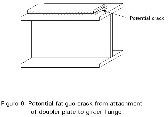
Firstly, because of the load transfer the stress concentration factor is high and hence the "basic" category of the weld is 50* when neither the flange plate nor the doubling plate is greater than 20 mm thick. If either exceeds 20 mm in thickness the category is reduced to 36*.
Secondly, not only will damage to the plate reduce the fatigue strength in a similar manner to that described above, but faults in the weld itself will reduce the strength since it is actually transferring load. An interesting development of this detail, which largely overcomes the problems described, is to omit the welding at the ends of the doubling plate and instead connect it to the flange plate in this region using high strength friction grip bolts, only beginning the welding (as a longitudinal fillet) after most of the load has been transferred. This weld will then behave as described for longitudinal fillets in Section 2.
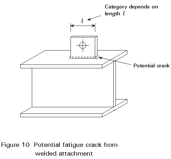
As can be inferred from Section 4.2 above, a load-carrying attachment is likely to have a lower category than a non load-carrying one. This statement must be treated with care, however, since sometimes an attachment intended to be non load-carrying may carry load; a typical case is a lug welded on, for example, to aid lifting during erection (see Figure 10). The lug is not intended to carry load in service but will, of course, tend to attract some. This circumstance is recognised in Eurocode 3 by varying the category depending on the length of the attachment in the direction of stress in the parent plate (the longer it is, the more load it will attract and hence the greater the stress concentration and the lower the category). Thus, even if it is nominally non load-carrying, it comes into the following categories (even lower categories would apply if the attachments were within 20mm of the edge of a plate):
length £ 50 mm: category 80
50 mm < length £ 100 mm: category 71
length > 100 mm: category 50*
If such attachments come in a fatigue sensitive area, a designer will normally require them to be removed and ground flush after use for erection; however, sometimes they are required in the final structure (e.g. batten plates, connection of bracing, etc.). In such cases care should be taken to detail them in such a way as to minimise the load transfer and hence the stress concentration. This is usually done by making them as short as possible and keeping them away from the extreme edge of members.
True load-carrying attachments (such as the doubling plate of Section 4.2, or load-carrying cruciform joints), are usually of very low detail category and are sensitive to weld defects in the same way as transverse butt welds. Furthermore, cruciform and similar connections can be very sensitive to lamellar faults in the plates, thus leading to lamellar tearing after welding. Such faults would have to be repaired - they cannot be quantified or allowed for by simply reducing the category of the weld.
Since the fatigue strength of welded joints is greatly influenced by the quality of the welds, the designer's first consideration in choosing a fatigue strength for design calculations must be the quality which can be achieved at economically justifiable cost and which can be shown to have been achieved by reasonably possible supervision of the welding process and inspection of the finished product.
Consider first longitudinal welds. The requirements for high fatigue strength are severe.
Any breakdown of an automatic welding process would drop a potential category 140 weld to category 125, or to category 112 unless the accidental stop/start position is repaired, and seen to be repaired, by a specialist.
To use a design strength of 140, therefore, requires faultless automatic welding under continuous supervision and rejection of any component with an accidental stop/start position at a highly stressed point.
Even category 125 requires a high degree of supervision to ensure identification and proper repair of any stop/start. The choice of lower categories reduces the need for supervision.
Inspection of longitudinal welds is difficult. For a start, a 30m long plate girder has 120m of longitudinal weld, some 30m of which would be stressed within about 10%of the maximum. Secondly, practicable methods of inspection are limited to visual - just looking at the weld - and magnetic particle methods to detect cracks.
Considerations of time and cost limit anything other than visual inspection to sample lengths, say a number of 1m lengths, making up a total of some 5% to 10% of the total length of weld. In addition, the ends of welds should be checked for cracks.
If such sample inspection reveals defects, the sampling rate must be increased to determine whether there is something wrong with the welding process.
The suggested sampling rate applies where the only function of the longitudinal welds is to hold web and flange together. In certain applications, such as crane girders or box girders, longitudinal welds may be subject to bending about their longitudinal axis or to concentrated vertical loads applied to the flange.
Eurocode 3 [1] gives categories for welds in such bending; category 71 for longitudinal butt welds and 50 for such partial penetration butt welds and fillet welds.
There is experimental evidence that welds at box girder corners can reach strengths corresponding to categories 80 or even 90, if butt welds, 125 if a pair of fillet welds, but only 50, as in Eurocode 3, if one-sided fillet welds. The stresses are taken as the greater of those in the weld or the parent metal.
This suggests that the strengths required for design in accordance with Eurocode 3 can be achieved with "ordinary" quality welds. Sample inspection, as for other longitudinal welds, should be sufficient but the sample size should be increased, probably doubled.
In relating strength requirements to inspection and quality criteria it should be considered that at least part of the partial factor in Eurocode 3 is intended to deal with variations in workmanship. For example, a factor of about 1,12 would cover the difference between a "perfectly" repaired stop/start position and a reasonably good one. If the repair led to slag inclusion, it would need a factor of 1,40 to cover the resulting loss in strength.
The total length of transverse butt weld in a girder is much less than that of longitudinal welds, say of the order of 4m. For this, and other reasons, they are more easily inspected than longitudinal welds. Even so, it is not possible to be sure of finding small internal defects and to size accurately those found.
In addition to visual inspection, two methods of non-destructive testing can be used - radiography and ultrasonics.
Essentially radiography records the intensity with which X-rays are transmitted through the weld onto photographic film. Porosity, for example, shows as dark grey spots on a grey background.
Radiography is costly, requires safety precautions difficult to arrange where there is 24 hour use of a workshop, and will not show thin defects such as lack of fusion, see Figure 11.
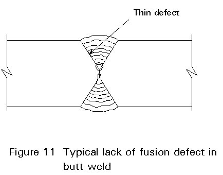
Ultrasonic testing can find such defects but is operator dependent. Even careful ultrasonic examination will, in most cases, miss defects of the order of 2mm2 in area - the sort of defect which may bring fatigue strength down to category 112.
The effect of defect size on fatigue strength was discussed earlier. The use of a given strength in design therefore implies a corresponding limit on defect size. Hence there is a need to measure the size of detected defects by ultrasonics.
In ultrasonic examination (Figure 12) defects are detected by the ultrasonic beam they reflect. The reflection is indicated on a display against a time base. The distance from the probe sending the beam is determined by the location of the echo mark. The height of the mark above the base measures the intensity of the reflected beam relative to that from some standard reflector.
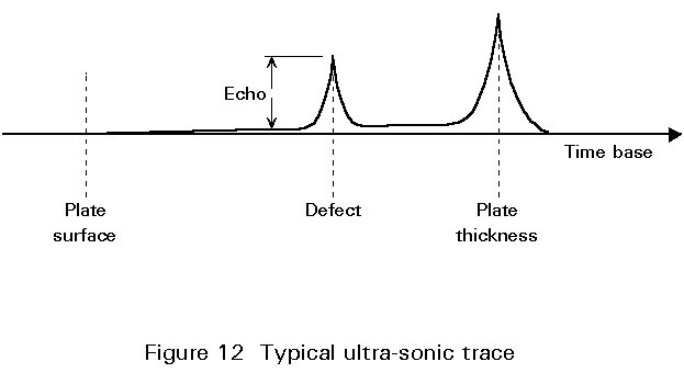
The boundaries of a defect are established by moving the probe until the mark of the defect echo has disappeared. The boundary is usually taken to be the centre of the probe at the position where the defect echo height is halved. This is not a precise measurement. Errors are of the order of 5mm on a defect dimension.
This method cannot be used when the dimension to be measured is less than the diameter of the probe - some 10mm in diameter or 79mm2 in area. The area of such small but significant defects can be determined by the proportion of the ultrasonic beam they reflect, i.e. the echo height. The strength of this reflection depends not only on the size of the defect but also on the efficiency of its surface as a reflector. Again, this is not a precise measurement. The same measurement of echo height can be produced by defects which differ in area by a factor of 2 if small, and a factor of 4 if large.
Defects which are acceptable for reasonable fatigue strength are small. The errors in determining their size by non-destructive testing are such that safe limits have to be set. This means that welds containing only acceptable defects will have to be rejected to be reasonably sure of not accepting welds with unacceptable defects.
Limits on defect size can be relaxed if part of the partial factor is taken to cover faults in workmanship. A factor of 1,25, for example, applied to category 112 strength would cover the sort of defects which can occur in good quality work.
As was shown in Section 4, the performance of transverse fillet welds and welds to attachments is less dependent on the quality of the welding than is the performance of butt welds or longitudinal fillets. Hence inspection of such welds is frequently confined to:
(a) visual inspection to ensure that the weld is of the right size, of a good profile, and does not suffer from excessive undercut.
(b) non-destructive testing (e.g. magnetic particle or dye penetrant) to ensure that there are no cracks in the weld or in the parent plate at the weld toe.
In certain applications, such as cruciform joints, it may be necessary to check the welding, probably by ultrasonic methods, to ensure that it has not caused lamellar tearing of the plate.
Where temporary gussets, etc. have been removed and ground, it is usual to check the surface of the ground plate for cracks.
A designer must appreciate that high quality is associated with considerable cost.
The costs arise from increased care in welding and supervision, inspection and repeated repair of rejected work. Repeated repair occurs because the quality of a repaired weld is often worse than that of the rejected weld. Added to this cost is the major cost of the delay caused to fabrication.
It is, therefore, important not to specify a higher quality than is justified on economic grounds or necessary on engineering grounds.
For economy must be balanced the cost of achieving a given quality against that of the extra material which would have to be used to reduce stresses to a level for which a lower quality would be acceptable.
Two considerations can limit the necessary quality.
Firstly, a part of a structure designed for the ultimate limit state may only be lightly stressed under fatigue loading, or may not be subject to many cycles of stress so that a detail category with a low fatigue strength is adequate. This situation applies, for example, to certain railway bridge girders above 40m span.
Secondly, the welded joint considered may not determine the fatigue strength of the component. For example, a stiffener or shear connector attached to the flange of a plate girder would bring the fatigue strength down to category 80 or even 71; in such a case there is no need to specify a quality of transverse butt weld in that flange which would give a fatigue strength corresponding to category 112. The same applies to the longitudinal welds attaching that flange to the web.
The best way of avoiding the consequences of joints with low fatigue strength is not to have such joints.
To show how to approach this desirable design, consider the plate girder shown in Figure 13, with cope holes, stiffeners, transverse butt welds in the flanges and longitudinal fillet welds.
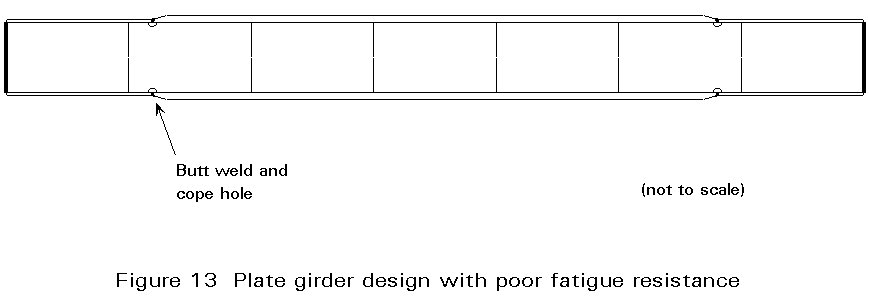
The cope holes limit the fatigue strength to category 71. Figure 6 showed that they are unnecessary and therefore they should not be there. Eliminating them is the first improvement.
The stiffeners, if more than 12mm thick, are in the same low category. They may be required to strengthen the web to resist shear forces or concentrated loads applied to the top flange, to resist lateral loads, e.g. wind forces, or to stabilise the top flange against lateral buckling.
If the stiffeners are only required to strengthen the web, they can be avoided if the web is made thicker. This improves the fatigue strength of the girder and will often be more economical than providing stiffeners, except in deep girders.
If the stiffeners are deleted, the fatigue strength of the girder is now limited by the transverse butt welds and the longitudinal fillet welds.
The transverse butt welds can and should be avoided if plates for the length of the girder can be obtained in one piece. This is on the basis that the butt welds are likely to cost more than the material which can be saved by using them. If butt welds must be used, they can and should be placed at a point where the fatigue strength of a reasonable quality weld does not limit the fatigue strength of the component. In short, they should not be placed at points of maximum stress.
If butt welds are made "harmless" as suggested, the longitudinal fillet welds remain. Here the choice of quality may be a matter of economics if the fatigue loading is such that it determines the design.
In short built-up girders where severe fatigue loading is the main design criterion, even longitudinal welds can be moved from highly stressed areas by using T sections for the flanges. This is not cheap, but may, in some cases, be economical.
Finally, if the required girder is short enough, it should be possible to find a rolled section which can be used without any welded joints, at least in highly stressed areas. This would achieve the objective of "no joints".
This short example does not, of course, represent all design problems. It does, however, show that it is often possible to reduce or eliminate the effect of joints on the fatigue strength of a component of a structure.
It must be remembered, however, that eliminating joints is not the primary objective in design. If joints are required they must be provided. Their design must be based on realistic assumptions as to their quality and fatigue strength.
[1] Eurocode 3 "Design of Steel Structures" ENV 1993-1-1:Part 1.1 General Rules and Rules for Buildings, CEN, 1992.
[2] British Standard BS5400: Part 10: 1980, Code of Practice for Fatigue, British Standards Institution, London
published by the European Rail Research Institute (ERRI), formerly ORE, Oudenoord 500, NL-3513 EX, Utrecht, The Netherlands.