ESDEP WG 12
FATIGUE
To introduce the more commonly used weld improvement techniques and their effects on the fatigue performance of welded joints.
Lecture 12.1: Basic Introduction to Fatigue
Lecture 12.2: Advanced Introduction to Fatigue
Lecture 12.3: Effect of Workmanship on Fatigue Strength of Longitudinal and Transverse Welds
This lecture introduces improvement techniques primarily as remedial measures for welded structures. Initial analyses of the reasons for the poor fatigue performance of welded joints leads to a classification system for improvement methods. The various methods used in practice are then described and evaluated. The methods described are:
The AWS improved profile
The use of special electrodes
Grinding
Weld toe remelting
TIG dressing
Plasma dressing
Hammer peening
Shot peening
Guidance on current design rules is summarised; the need for improvement to design standards and guidance is highlighted.
Any weld in a structure usually represents a weakness both with regard to brittle fracture and fatigue strength. The low fatigue strength of welded joints is a limiting factor for the design of more efficient structures, in particular since the fatigue strength normally does not increase with static strength. Upgrading the fatigue performance of a welded structure can be achieved in several ways such as:
Improvement methods are usually employed as remedial measures to extend the fatigue life of welds that have failed prematurely and have been repaired. They are also used to extend the life of welds which, through service load monitoring, have been shown to be more severely loaded than assumed during the design phase.
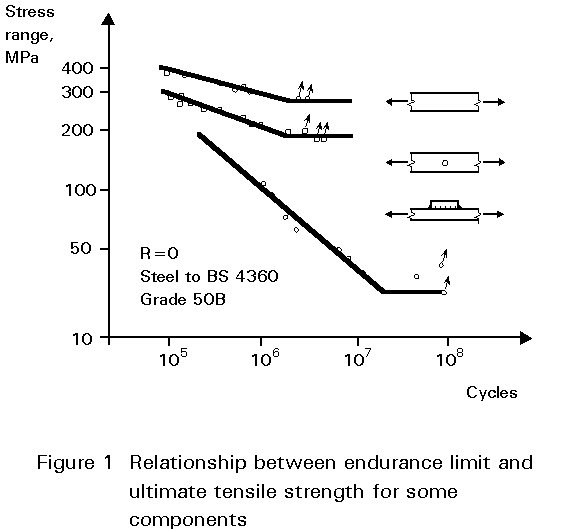
The incentive for applying improvement methods is to make an improved welded joint behave like a mildly notched component, as shown in Figure 1.
The use of higher allowable stresses for welded joints in higher strength steels entails other benefits as well: the thickness effect in fatigue is reduced, bringing about a further reduction in weight as compared with a lower strength steel joint with the same load bearing resistance. A reduced size of section in general also improves the brittle fracture properties of the joint. The lower welding, handling and erection costs may partially offset the higher fabrication expenses incurred by the improvement methods.
In this lecture the emphasis is on the degree of improvement in fatigue strength which it is possible to obtain using the various improvement techniques. However, from a practical point of view, other considerations such as cost and reliability of the treatment (quality assurance) may be important. Various aspects of quality control and cost are discussed briefly at the end of the lecture.
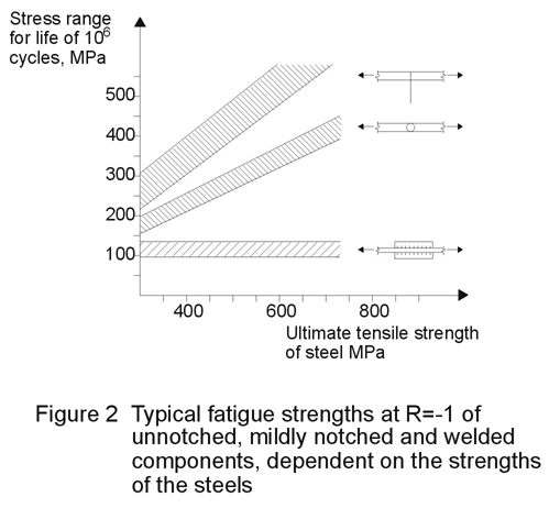
To understand the full potential of improvement methods for fatigue life, it is useful to look at the reasons for the poor fatigue performance of welded joints. The low fatigue strength of welded joints as compared with other notched components is illustrated in Figure 2. Welded joints differ from other notched components in several ways even if the elastic stress concentration factors Kt are similar. It is important to identify the main factors that tend to reduce fatigue life in order to choose efficacious methods for improving the fatigue performance. The main differences between welded and unwelded, notched components are:
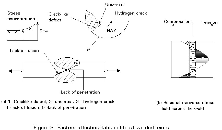
(a) Notch shape and defects: The geometrical notch of the weld toe region, which normally is the most fatigue critical area, is generally less uniform than notches in a machined component, see Figure 3. Moreover, welded joints contain an assortment of defects, most of which are so sharp that they start growing as fatigue cracks when the structure is subjected to dynamic loads, thus reducing or eliminating the crack initiation stage of the fatigue life.
(b) Metallurgical changes in the base material: The material in the heat affected zone (HAZ), in which the fatigue crack is likely to initiate and propagate, undergoes metallurgical changes that may affect the local fatigue properties. Thus the softened material in the HAZ of a higher grade steel, whose high strength has been obtained by thermo-mechanical treatment, may limit the fatigue strength that is possible to obtain by improvement techniques.
(c) Residual stresses are set up in and near the weld due to the contraction of the weld metal as it cools to ambient temperature. These local residual stresses due to welding, which may reach the yield stress in magnitude, affect the fatigue properties in a similar manner to externally imposed mean loads, i.e. a tensile residual stress reduces fatigue life while a compressive stress increases life. The distribution of transverse residual stresses in a welded plate of simple shape is shown in Figure 3(b).
Residual stresses do not arise only from the thermal strains associated with the welding process and subsequent cooling. Global or long range residual stresses are introduced in a structure whenever members are forced together, due to misfit, uneven thermal expansion or when restraint is being used. Long range stresses act over large areas and are therefore not relaxed by peak loads at stress concentration or by local treatment. They are generally of smaller magnitude than welding stresses.
(d) Environmental effects: A corrosive environment may have a strong adverse effect on fatigue life. The fatigue lives of common welded joints are typically reduced by a factor of two or four under free corrosion in seawater. However, the prevention of corrosion by either cathodic protection or protective coatings, which may restore the air fatigue properties of a welded joint, are not regarded as improvement methods per se because corrosion protection is part of normal practice for the construction and operation of offshore structures.
The low fatigue strength of welded connections is generally attributed to the very short crack initiation period which is generally found to be in the range of about 10 to 30% of the total life, depending on the method of observation and definition of the initial crack. Comparing this with a crack initiation period of more than 90% typically observed for smooth specimens tested at low stresses, there is obviously scope for a substantial life increase by delaying crack initiation. The principal ways of achieving this increase are by:
(a) Reducing the stress concentration factor of the weld.
(b) Removing the crack-like defects at the weld toe.
(c) Removing the harmful tensile welding residual stresses or introducing compressive stresses.
Since both (a) and (b) both involve altering the local geometry, weld improvement methods can be placed in two broad categories:
(1) Weld geometry modification methods
(2) Residual stress methods.
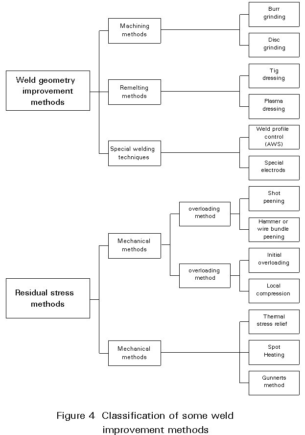
Various methods which have been investigated [1,2] are listed in Figure 4. Table 1 presents an evaluation of the improvement methods that are currently used in practise, together with some information on relative costs where available. In addition, two other methods have been tried in the last few years; water gouging and laser remelting. However, the two methods are still very much experimental in nature and have, as far as is known, not been employed in industry. The following methods have reached a more mature stage in the sense that they are used in industrial applications:
(1) Weld toe grinding, using either a disk grinder or a rotary burr tool.
(2) Tungsten inert gas (TIG) remelting of the weld toe region.
(3) Weld profile control, i.e. performing the welding such that the overall weld shape gives a low stress concentration and the weld metal blends smoothly with the plate.
(4) Special electrodes with good wetting characteristics to give a favourable weld toe geometry.
(5) Hammer peening of the weld toe region.
(6) Shot peening.
Grinding and TIG remelting methods may be classed as weld toe geometry modification methods, whereas hammer preening and shot preening are residual stress techniques.
Particularly large improvements may be obtained when techniques from the two groups are combined.
Weld profiling and the use of special electrodes are methods that are integral parts of the welding process itself. These methods are attractive from a production point of view since there is no need to come back with a different type of equipment for a final treatment of the weld, which would increase costs and make quality control more difficult.
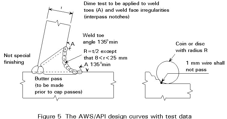
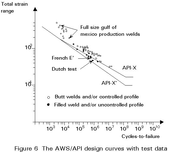
In the Structural Welding Code [3] of the American Welding Society (AWS), a low stress concentration factor is sought by controlling the overall shape of the weld to obtain a concave profile and requiring a gradual transition at the weld toe. The "disc test" or "dime test" shown in Figure 5, as specified by AWS, is used to ensure an acceptable weld. If the weld does not pass the disc test, remedial grinding at the weld toe or at the interbead notches has to be carried out. If profile control is carried out the designer can use the X curve in Figure 6, if not the lower X¢ curve must be used.
Specially developed electrodes with coatings that have good wetting and flow characteristics have been used in Japanese test programs aimed at improving the fatigue performance of high strength steels of 500 to 800 MPa yield strength [4]. These electrodes are understood to have been widely used in the construction of high strength steel bridges. The electrodes give a smooth transition at the weld toe and a reduction of the calculated stress concentration factors, typically from around 3 to 1,2-1,5 for fillet welds. The improvements reported in the Japanese tests were from 50 to 85%, the largest increases in fatigue life being reported for the highest strength steels. However, other tests on T-joints made recently in Norway gave improvements of approximately 25%. The main doubts about special electrodes concern their use in positional welding where the easy flow of the filler material may be a disadvantage.
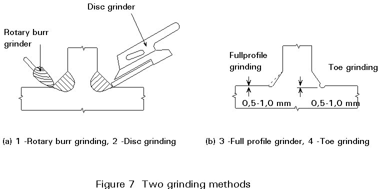
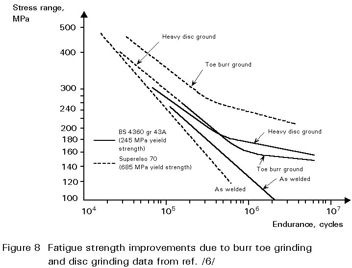
Grinding (Figure 7) can be carried out with a rotary burr grinder or disc grinder, the former requiring much more time and therefore incurring higher costs. To ensure the removal of slag intrusions, grinding has to be extended to a minimum depth of 0,5mm below the bottom of any visible undercut [5]. The lower stress concentration factor and the removal of crack-like defects at the weld toe generally give large increases in fatigue life, typically from 25 to 100% at long lives (N > 1 million cycles), see Figure 8 [6]. However, the scatter is large, particularly for disc grinding which may be difficult to perform in confined areas; also an inexperienced operator may inadvertently remove too much material.
Grinding is currently the only improvement method allowed in European codes for offshore structures [5,7]. However, the higher fatigue strength is not intended for use in initial design, instead grinding may be used as a remedial measure if the design life is shown to be inadequate at a late stage during design or construction.
Remelting of the weld toe using either TIG or plasma welding equipment generally results in large gains in fatigue strength, for several reasons. Firstly, the smoother weld toe transition reduces the stress concentration factor; secondly, slag inclusions and undercuts are removed; and thirdly, according to some Japanese publications, the higher hardness in the heat affected zone is claimed to contribute to the higher fatigue strength.
Plasma dressing generally tends to give better results than TIG dressing. This with plasma dressing.
Standard TIG dressing equipment is used, usually without any filler material. For the older type C-Mn steels (e.g. St 52) with a relatively high carbon content, a second TIG round was necessary to temper the first run at the toe [8], see Figure 9. The second run also contributes to a better weld toe geometry. The hardness problem associated with TIG dressing of C-Mn steel is eliminated with the use of modern low carbon steels. TIG dressing is somewhat sensitive to operator skill, the weld and plate must be clean to avoid pores.
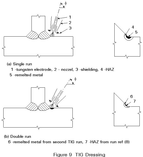
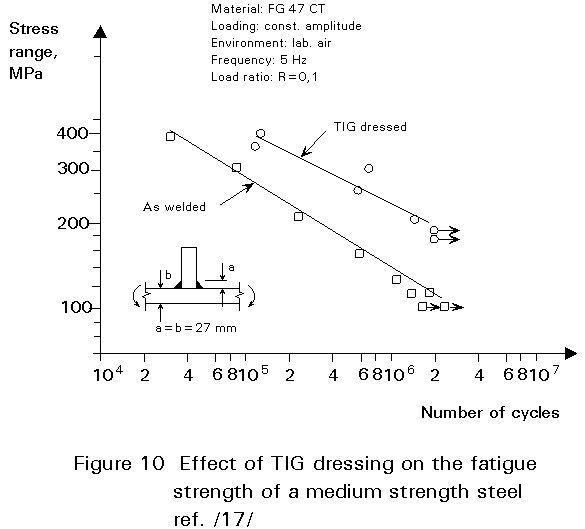
The magnitude of the improvement depends as for most improvement techniques, primarily on the joint severity and base material strength. Improvements ranging from about 10% for butt welds in mild steel plates to about 100% for fillet welded high strength steels have been reported. Figure 10 shows typical results in the latter case [8].
Plasma dressing is similar to TIG dressing, the main difference being the higher heat input (about twice that used in TIG dressing), and a wider weld pool. The latter tends to make plasma dressing less sensitive to electrode position relative to the weld toe, and the resulting improvements in fatigue strength are generally larger than for TIG dressing.
Some improvement in fatigue behaviour is obtained by removing residual welding stresses by postweld heat treatment, especially if the applied load cycle is wholly or partly in compression. However, the largest benefits are obtained if compressive residual stresses are introduced. The more commonly used residual stress methods are hammer peening and shot peening.
Hammer peening is carried out with a solid tool with a rounded tip of 6-14mm radius. A similar technique consists of using a wire bundle instead of a solid tool. Both types of tool are normally pneumatically operated. The solid tool gives a far more severe deformation and gives better improvements than either wire bundle or shot peening [6].
Optimum results for hammer peening are obtained after four passes, giving a severely deformed weld toe, with an indentation depth of about 0,6mm, providing a simple inspection criterion [6].
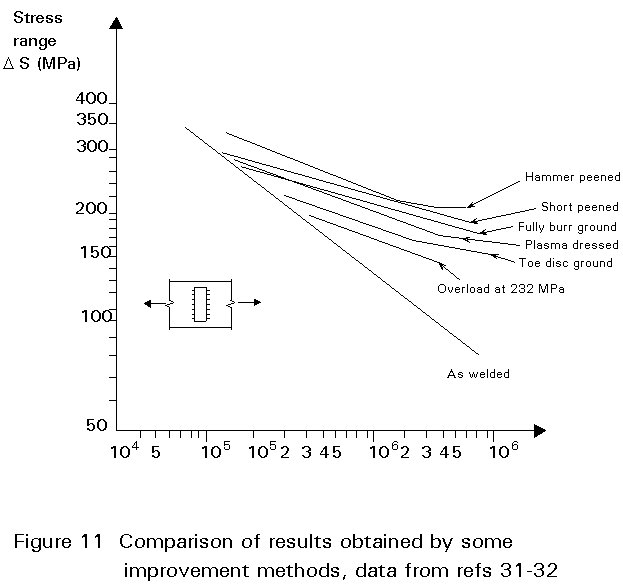
Like burr toe grinding, hammer peening is a noisy and tedious operation and has perhaps, for this reason, not attained widespread use. The improvements are among the highest reported, see Figure 11. Most test results show larger improvements for higher strength steels [6].
In the shot peening process the surface is blasted with small steel or cast iron shots in a high velocity air stream, producing compressive residual surface stresses of about 70 to 80% of the yield stress. Assessing the quality of the treatment entails time consuming residual stress measurements. In practice, the intensity or the degree of surface plastic deformation is determined by Almen strips, which are small steel strips attached to the surface of the component. The curvature developed in the strip is a measure of the peening intensity. A second parameter is area coverage. 100% coverage is obtained when visual examination at 10X magnification of the surface shows that all dimples just overlap. The time required to obtain 100% is doubled to obtain 200% as normally specified. A major advantage of shot peening is that it covers large areas at low cost.
Results from fatigue tests on shot peened welded joints show substantial improvements for all types of joints, the magnitude of the improvements varying with type of joint and static strength of the steel. Typical results are 30 to 100% increase in fatigue in fatigue lives in the long life region; however, at shorter lives (N < 105 cycles) the improvements tend to disappear. Tests in sea water show that the improvements are retained even under freely corroding conditions [9].
High peak loads in variable amplitude loads sequences may be assumed to relax the residual stresses and reduce the efficacy of such methods, but German results have shown no such adverse effects [9].
The combination of two improvement methods, particularly a weld geometry method and a residual stress method, are likely to give large improvements. One example is full profile grinding and hammer peening which resulted in the fatigue strength of fillet welds in mild steel being restored to that of the base material [10]. More common combinations are grinding and shot peening and AWS weld profile control and shot peening [11]. In such cases the resulting improvement may be double that of a single method.
Most current knowledge on improvement methods has been gained from tests on small scale planar specimens. When considering the application of weld improvement methods to actual structures, the differences in fatigue behaviour has to be evaluated. One important factor is size. In a large structure long range residual stresses due to forcing the members together are present and influence fatigue life. Another consideration is the existence of alternative failure sites. Obviously no improvement can be expected for a joint with load-carrying fillet welds whose toe regions are ground or TIG dressed if the untreated joint is as likely to fail from the root as from the toe; the failure would only be shifted to the root.
In contrast to small joints where the peak stress is limited to the weld toe, the peak stress region in a large multi-pass joint may include several weld beads. Cracks may initiate anywhere in this highly stressed area.
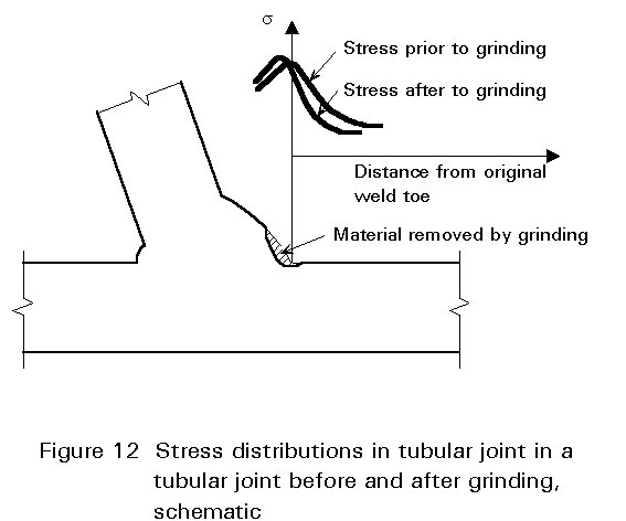
In some welds, e.g. in tubular joints with low beta ratios, there is a very steep stress gradient at the weld toe which is caused partly by the global geometry. If the weld leg length is reduced, e.g. by grinding as indicated in Figure 12, the resulting peak stress may well be higher and the resulting improvement could be marginal or non-existent.
As noted in Section 3.1 the weld profile improvement method is included in the AWS/API design rules in terms of the X curve that may be used generally if profile control is carried out, otherwise the lower X must be used. The two curves intersect at a life that is somewhat less than 104 cycles, i.e. the improvement is lost at this life.
In the UK Department of Energy rules, S-N the curves for all types of joints can be moved by a factor of 1,3 on strength (2,2 on life) if grinding is carried out [5]. Thus the two curves are parallel, and the improvement applies also in the low life/high stress region, contradicting most test data which tend to show very small or no improvements at all in this region, i.e. giving intersecting as-welded and improved S-N curves, as exemplified by Figure 11.
The Swedish design code [12] for welded structures consists of 10 S-N curves, each of which is identified by its Kx factor, see Figure 13. The code also includes a weld quality system containing four basic classes plus an additional class designated U for improved fatigue strength. Use of the improved class requires that:
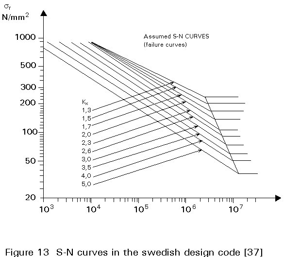
The use of improvement techniques such as grinding, TIG dressing and hammer peening is permitted to obtain the highest quality class. The combination of weld geometry, probability of survival level, and weld quality thus determines the S-N curve to be used. The Swedish system of S-N curves is similar to the British rules insofar that employing an improvement method leads to a parallel shift of the S-N curve.
Size effects in notched components are generally attributed to three origins [13], i.e. a technological size effect, a statistical size effect or a geometrical or stress gradient size effect.
Technological size effects result from differences in production parameters, generally leading to lower mechanical strength for the thicker parts. Also residual stresses and surface quality may vary with thickness.
Statistical size effects arise from the higher probability of encountering a large defect in a large volume of material compared with a smaller volume.
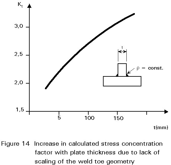
Geometric size effects arise from the stress gradient at the notch root. Even if geometric scaling is maintained the stress gradient is steeper for the thicker part and a crack will grow in a higher stress field. If geometric scaling is not maintained which is usually the case for welded joints, the stress magnification factor increases with thickness, see Figure 14.
Fracture mechanics calculations [14] have shown that the influence of thickness increases with the SCF of the joint. A statistical analysis of published data on size effects in welded joints gave a size exponent of n=0,33 for as-welded joints and n=0,20 for improved joints, where n is the size exponent in the thickness correction equation
S/So=(to/t)n (1)
This tendency to get a smaller influence of size for unnotched or mildly notched parts has been shown to exist for mechanical components and the following relation between n and the SCF has been proposed [13]
n=0,1 + 0,14logKt (2)
The current status of improvement methods is not satisfactory as several methods with proven ability to improve the fatigue strength of a large variety of small scale specimens as well as large structural components are not included in design rules. Moreover, the European rules [5, 7, 13] which give the same improvement at all lives, are not consistent with test data which indicate that the largest improvements are obtained in the high-cycle region, and very small or no improvements occur in the low-cycle region (N < 104 cycles).
Secondly, both theoretical and experimental results indicate that size effects are less severe for mildly notched parts than for the more severe joints with very short crack initiation lives. Thus a size exponent of 0,2 would probably be adequate for low SCF joints like simple butt welds or T-joints with small attachment thicknesses. For the higher SCF joints, e.g. Class F and lower, a size exponent of n=0,33 would be more suitable [13]. For improved welds an exponent n=0,2 for all weld classes would probably be adequate.
Life predictions that include a crack initiation stage using local stress strain concepts plus fracture mechanics methods for the crack growth stage have given reasonably accurate life estimates for improved welds [6], and support the experimental observation that the fatigue lives of improved welds generally increase with base material strength. Thus a third, and perhaps more controversial modification to the design rules, would be to allow higher fatigue strength for higher strength steels. However more data has to be collected before specific recommendations regarding the degree of improvement can be made.
An effort is now being made within the International Institute of Welding's Commission: Fatigue Behaviour of Welded Components and Structure, to collect data on improvement methods with the aim of developing recommended shop practices and design guidance for improvement methods.
[1] Haagensen, P.J.: "Improving the Fatigue Strength of Welded Joints", Fatigue Handbook. Offshore Steel Structures. Ed. A. Almar Naess, Tapir 1985.
[2] Bignonnet, A.: "Improving the Fatigue Strength of Welded Steel Structures", PS4, Steel in Marine Structures, Int. Conf. Delft, Elsevier, June 1987.
[3] Structural Welding Code - Steel, ANSI/AWS D1.1-86, American Welding Society, Feb. 1986.
[4] Kobyashi, K. et al.: "Improvements in the Fatigue Strength of Fillet Welded Joint by Use of the New Welding Electrode", IIW doc. XIII-828-77.
[5] Department of Energy, "Offshore Installations: Guidance on Design and Construction". HMSO, London 1984.
[6] Knight, J.W.: "Improving the Fatigue Strength of Fillet Welded Joints by Grinding and Peening", Welded Res. Int. Vol. 8(6), 1978.
[7] "Fatigue Strength Analysis for Mobile Offshore Units", Det Norske Veritas Classification Note 30.2, Aug. 1984.
[8] Haagensen, P.J.: "Effect of TIG Dressing on Fatigue Performance and Hardness of Steel Weldments", ASTM STP 648, 1978.
[9] Grimme D. et al.: "Untersuchungen zur Betriebsfestigkeit von geschweissten Offshore-Konstruktionen in Seewasser", ECSC Agreement 7210 KG/101 Final Report 1984.
[10] Gurney, T.R.: "Effect of Grinding and Peening on the Fatigue Strength of Fillet Welded Joints", British Welding Journal, December 1968.
[11] Haagensen et al.: "Prediction of the Improvement in Fatigue Life of Welded Joints due to Grinding, TIG Dressing, Weld Shape Control and Shot Peening", TS35, Steel in Marine Structures, Int Conf. Delft, Elsevier, June 1987.
[12] Swedish Regulations for Welded Steel Structures 74 StBk-N2, National Swedish Committee on Regulations for Steel Structures, 1974.
[13] Haagensen, P.J. et al.: "Size Effects in Machine Components and Welded Joints", Paper 1017, Houston, Texas, 1988.
[14] Maddox, S.J. "The Effect of Plate Thickness on the Fatigue Strength of Fillet Welded Joints", The Welding Institute, 1987.
Table 1 Evaluation of Improvement Methods
|
GROUP |
METHOD |
ADVANTAGE |
DISADVANTAGE |
COST COMPARATOR |
|
GEOMETRY IMPROVEMENT METHODS
|
GRINDING METHODS General |
Relatively simple and easy to perform. Give large improvement |
Applicably mainly to planar joints that can be expected to fail from the toe. All grinding techniques give a poor working environment regarding noise and dust. Access to weld may be a limiting factor. |
|
|
Relatively simple to perform, inexpensive. Simple in section criterion (depth min. 0,5 mm below plate surface or undercut). |
Marginal increase can be expected for large size welds tubular joints due to stress concentration effect of groove. |
|||
|
Full profile burr grinding |
Very slow. Expensive due to high labour costs and high tool wear rate. |
Large improvements to be expected for all types of welds. |
20 |
|
|
Disc grinding |
Very fast compared with burr grinding. Can cover large areas. |
Score marks give lower improvements than burr grinding. Improper use may introduce serious defects. |
2 |
|
|
REMELTING METHODS General |
Large improvements are possible. Suitable for mechanisation. |
Operator needs special training |
||
|
TIG dressing |
Small physical effort required. Inexpensive |
Careful cleaning of weld and plate necessary. High hardness may result in C-Mn steels due to low heat input. |
1 |
|
|
Plasma dressing |
Easy to perform due to large weld pool |
Lower hardness than TIG dressing |
N/A |
|
| Somewhat large improvement than TIG dressing |
Heavy, cumbersome equipment. Accessibility may limit use |
|||
|
WELD PROFILING METHODS General |
The improvement is introduced in the welding process itself. |
Defects at weld toe not removed. |
||
|
AWS improved profile |
Well defined inspection criterion (the "dime test") Suitable for large welds and tubular joints |
Very large scatter in test results due to variation in microgeometry at weld toe. Consistent improvements only possible if method is combined with others, e.g. toe grinding, hammer peening or shot peening. |
N/A |
|
|
Special electrodes |
Easy to perform. Suitable for small joints. Inexpensive. |
Improvement smaller than, e.g. grinding or TIG dressing. |
N/A |
Table 1 (Continued)
|
GROUP |
METHOD |
ADVANTAGE |
DISADVANTAGE |
COST COMPARATOR |
|
RESIDUAL STRESS METHODS
|
General |
Large improvements possible. |
Not suitable for low cycle fatigue applications. Beneficial effects may disappear under variable amplitude loading involving peak compressive loads. |
|
|
Hammer peening |
Very large improvements possible for poor quality welds. |
Limited to toe treatment only. |
2 |
|
|
Simple inspection criterion (depth of groove > 0,6mm). |
Excessive peening may cause cracking. |
|||
|
Shot peening |
Well developed procedures for small parts. Covers large areas. |
Practicable application to large scale structures not demonstrated. |
N/A |
|
|
Simple methods for quality control. |
Best suited for mild notches. |
|||
|
Improves resistance to stress corrosion cracking. |
Very thin surface layer deformed; corrosion may quickly remove beneficial effects. |