
ESDEP WG 9
THIN WALLED CONSTRUCTION
To provide general information on problems related to the design of connections when thin-walled members or elements are used.
Lecture 3.4: Welding Processes
Lecture 11.1.2: Introduction to Connection Design
Lecture 11.3.1: Connections with Non-Preloaded Bolts
Lecture 11.5: Simple Connections for Buildings
Lectures 14.1.1: Single Storey Buildings: Introduction and Primary Structure
Lecture 14.1.2: Single Storey Buildings: Envelope and Secondary Structure
Practical treatment of the main aspects of connection design in thin-walled steel sections is given, including: Types of fasteners and connections, structural and non-structural requirements, factors affecting the forces on the connection as well as the distribution of forces in the connection, and failure modes of fasteners.
Connections play an important role in structural design. They influence significantly the performance of the structure as well as its cost. A proper selection and design of frame connections may make a substantial contribution to the competitiveness of steelwork. This fact was recently recognised by Eurocodes 3 [1] which introduced realistic connection models and gave basic specifications to account for connection response in design. With reference to lightweight structures comprising cold-formed steel sections, the connections may play a substantial role in the behaviour of certain typical forms of construction, such as for example, in systems designed by the stressed skin design method presented in Lecture 9.5.
A variety of joining methods between cold-formed sections is available; most of them are specific to thin steel, though fasteners generally used for hot rolled sections, i.e. for thicker plates, may also be used provided that differences in behaviour are taken into account.
This lecture has the main purpose of:
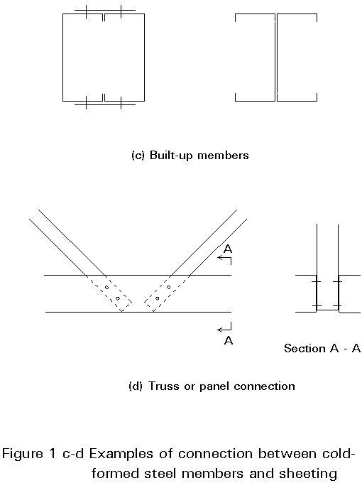
A relatively large number of connections of different types are needed in building construction using cold-formed steel sections. An attempt to identify the main connection types encountered in these structural systems is illustrated in Figure 1. Connections between sheeting and members are of great importance for frames designed by the stressed skin design method, while connections using sleeved or overlapping purlins are typical of lightweight roofing. Increasingly, thin steel sections are used in building frames and beam to column and beam to beam connections have to be designed.
The important aspects of joining cold-formed sections and/or sheeting are:
Two main categories of fastening may be identified:
Both categories will be reviewed briefly in the following sections.
Different types of mechanical fasteners as well as their general field of application are presented in Table 1. The guidelines of the manufacturers of the fasteners will provide information concerning how to treat attachments to "thin" and "thick" steel sections.
General information about the use of each type of fastener is given below, in order to provide background for proper selection and use.
Bolts with nuts
Bolts with nuts are threaded fasteners which are assembled in preformed holes through the elements to be joined. Thin members will necessitate the use of fully threaded bolts.
For thin-walled sections the bolt diameter range is usually from 5 to 16mm: the preferred bolt Classes are 8.8 or 10.9. High strength slip resistance bolts are not recommended for total thicknesses less than 8mm due to loss of preload in the bolts due to the creep of the zinc layer.
Screws
Two main types of screws can be distinguished:
a. self tapping screws: thread forming screws and thread cutting screws;
b. self drilling screws.
Most of the screws will be combined with washers to improve the load-bearing resistance of the fastening and/or to make the fastening self-sealing.
Some types are available with plastic heads or plastic caps for additional corrosion resistance and colour matching.
Figure 2 shows the thread-types for thread forming screws: type A is used for fastening thin to thin sheets, type B for fixings to steel elements of a thickness greater than 2mm, type C for fixings to thin steel elements of a thickness up to 4mm.

Thread forming screws normally are fabricated from carbon steel (plated with zinc for corrosion protection and lubrication) or stainless steel (plated with zinc only for lubrication).
Figure 3 shows some examples of thread and point-of-thread cutting screws. Thread cutting screws have threads of machine screw diameter-pitch combinations with a blunt point, and tapered entering threads have one or more cutting edges and chip cavities.

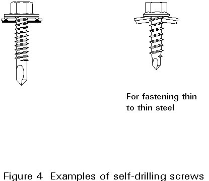
Thread cutting screws are used for fastening to thicker metal elements. Resistance to loosening is normally not so high for thread cutting screws as for thread forming screws. Thread cutting screws are fabricated from carbon steel case hardened and normally plated with zinc for corrosion and lubrication. Self drilling screws drill their own hole and form their mating thread in one operation. Figure 4 shows two examples of self-drilling screws. Self drilling screws are normally fabricated with carbon steel heat treated (plated with zinc) or with stainless steel (with carbon steel drill point).
Blind rivets
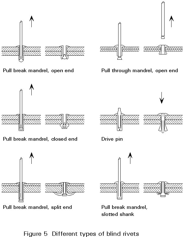
A blind rivet is a mechanical fastener capable of joining work-pieces together where access to the assembly is limited to one side only. They are installed in pre-drilled holes and are used for thin to thin fastenings. Blind rivets are available in aluminium alloys, monel (nickel-copper alloy), carbon steel, stainless steel and copper alloy.
Figure 5 shows different types of blind rivets.
Shot fired pins
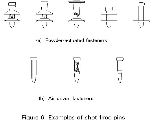
Shot fired pins are fasteners driven through the element to be fastened into the base metal structure. Depending on the type of driving energy they can be grouped as:
Figure 6 shows examples of shot fired pins.
Seam locking
Seam locking (see Table 1) in structural application will be mainly used as longitudinal connection between adjacent roof sheets.
In lightweight construction resistance welding is generally used besides more conventional arc welding techniques (Electrode, Gas Metal Arc, Tungsten Inert Gas Welding).
Main types of resistance welding are:
These techniques are illustrated in Figure 7.
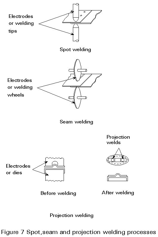
Basically resistance welding involves a co-ordinated application of electric current and mechanical pressure of the proper magnitude and duration and a proper surface of the steel sheet. Resistance welding is also possible for zinc coated material, but the welding parameters differ from those for uncoated material.
Both types of welding (arc and resistance welding) can be used for connecting either thin to thin elements or thin to thick elements.
Structural and non-structural requirements should be considered for an effective and reliable design of connections. The former will mainly be accounted for in sizing and checking the connection, as well as when defining the most appropriate details, whilst the latter should be referred to when selecting the most appropriate fastening type for the specific case. A list of the most important non-structural requirements is provided in Table 2.
Structural requirements can be summarised by the main features the connection behaviour must fulfil, i.e. stiffness, strength and deformation capacity (see Figure 8), described as follows:
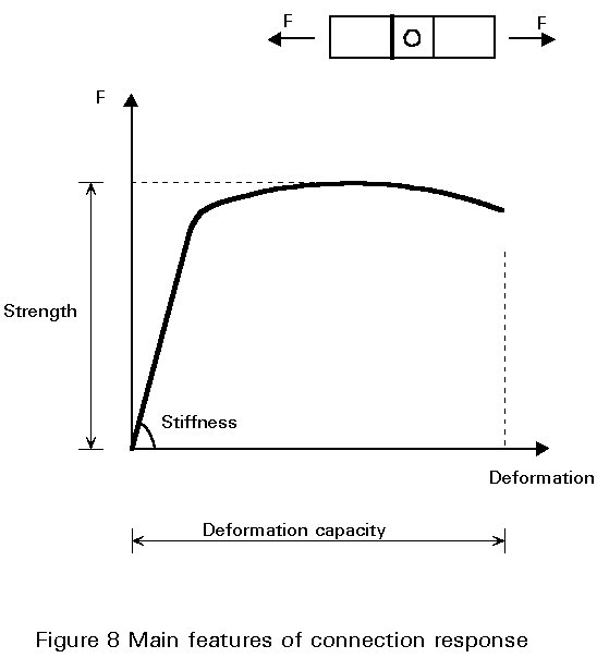
a. Stiffness
The stiffness of a connection is important because it determines the stiffness and hence deflection of the whole structure or of its components. Moreover the stiffness of the connections will influence the force distribution within the structure. Especially when the connection is a part of a bracing structure, then the stiffer the connection the lower the bracing force will be.
Special systems are available where cold-formed sections interlock to form a connection with a good bending and shear stiffness.
b. Strength
Connection strength ensures the capability of resisting forces and moments determined by the analysis of the structure subject to the combinations of actions related to the ultimate limit state condition.
The strength of the connection mainly depends on:
1. the type of fasteners, and
2. the properties of the connected elements (thickness, yield stress).
A reliable assessment of the strength can be achieved in many cases only by testing. However, Eurocode 3: Part 1.3 [1] provides formulae to determine shear and tension resistance of most common fastener types, together with the range of applicability.
Connections between thin elements, e.g. trapezoidal sheeting, are sensitive to repeated loads when they are working in tension. Eurocode 3: Part 1.3 covers this case also by increasing the gM factor in presence of dynamic loads comparable to wind load.
c. Deformation capacity
Deformation capacity is required in order to allow local redistribution of forces without detrimental effects. Otherwise brittle fracture might be caused by local overloading. A proper detailing and fastener selection is vital in order to ensure sufficient deformation capacity to the connection.
The main modes of failure for different types of fasteners are presented briefly in Section 4.3.
Forces and moments, due to the response of the whole structure to design loads, are resisted by the connection through shear and tension forces induced by the individual fasteners.
Basically each fastener will be subject to forces which depend on:
It is useful also to distinguish between:
Two types of connections are now considered in more detail, in order to highlight several aspects related to the force distribution between connected members.
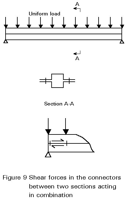
a. Connections in thin-walled sections
× Consider two similar sections attached together so that, in order to develop their combined strength, the connections are loaded in shear (see Figure 9): The maximum shear force in the fastenings occurs at the ends of the span and is calculated from the formula:
SA =
where
SA is the sum of shear forces in both fastenings in a cross-section A.
a is the distance between the fasteners in the span direction.
A is the area of one section.
V is the vertical shear force at the support.
y is the distance of the centroid of the area of one section to the neutral axis of the composite beam.
I is the moment of inertia of the combined sections.
The calculation method shown gives an upper limit to the shear force in the fasteners. In reality some slip in the fasteners will occur. This causes a smaller section modulus and moment of inertia of the composite beam leading to slight increase in deflections.
Consider next an I-beam made from single C-sections as shown in Figure 10. Because each C-section would twist if not connected, tension forces occur between the C-sections when connected. The tension force T in the upper bolts can be determined knowing the shear centre of the C-sections.

Secondary forces in connections: Care should be taken, by suitable detailing, that second order effects caused by deformation of thin-walled sections will not generate extra forces in the fastenings.
b. Connections in profiled sheeting
It is convenient to discuss these connections by referring to types of forces they should resist:
Shear forces:
× The dead weight of steel sheets in wall or facade elements.
× Diaphragm action, when the diaphragm is used deliberately in the absence of a wind bracing, or to provide lateral support for beams or columns.
× Variation of the temperature of the steel sheets; with sufficient deformation capacity the shear forces will be small and may be neglected.
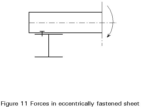
× Rotation of the eccentric fastened sheet ends and the membrane-action of the sheet (see Figure 11), in the presence of sufficient deformation capacity the fastening will not fail.
× Diaphragm action which is not used structurally. It may occur when a sheeting or cladding is only used as an outer skin; it is then necessary for the cladding to follow the deformations of the sub-structure; this is possible when the diaphragm (especially the fastenings) possesses sufficient deformation capacity.
Tension forces:
Tension forces will be caused mainly by loads perpendicular to the plane of the steel sheets. For the determination of the required resistance and stiffness of the sheets a simply supported static system is assumed. In reality the sheets are to some extent restrained at the supports; but for the design of the sheets it is safe to neglect the restraining effect.
Overstress can arise in fasteners due to bending of the steel sheet over the supports as in Figure 11. The bending causes an accidental restraining moment of the steel sheets, which generates an extra tension force in the fastener which is known as a prying-force. The magnitude of the prying force depends on:
× the stiffness of the sheets in relation to the span.
× the flexibility of the sheets near the fastener.
× the diameter of the head of the fastener or the diameter and stiffness of the washer.
× the distance between the fastener and the contact points A or B.
× the torsional rigidity of the support.
When sufficient deformation capacity is available the required rotation can take place and design can be based on the reaction ignoring these effects.
Strength and deformation capacity of connections depend substantially on the failure mode of the fastenings. These modes are reviewed below.
a. Fasteners Loaded in Shear
Several failure modes can occur which are illustrated in Figure 12.
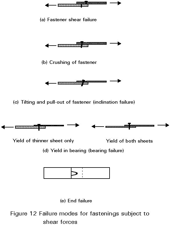
× Shear Failure (Figure 12a)
Shear failure may occur when the sheet is thick with reference to the fastener diameter, or when an unsuitable fastener is used. This is a relatively brittle form of failure and is not preferred.
× Crushing of the Fastener (Figure 12b)
Crushing may occur with hollow fasteners, and in combination with tilting and yield in bearing.
× Tilting and Pull-out of Fasteners: inclination failure (Figure 12c)
It is the normal mode of failure in thin sheet to thin sheet fastening in which the threads or the site formed rivet heads pull out of the lower sheet. It may occur in combination with yield of both sheets in bearing, and in conjunction with considerable sheet distortion.
× Yield in Bearing: bearing failure (Figure 12d)
Two cases may be encountered: yield may occur only in the thinner sheet or in both the connected sheets. It is the most ductile mode of failure.
× End Failure (Figure 12e)
This failure may occur only when recommended end distances are not achieved.
× Failure at the Net Cross-Section
Failure by fracture of the net cross-section may occur if the tensile resistance of the steel sheet is less than the shear resistance of the fastener.
b. Fasteners Loaded in Tension
Several failure modes can occur which are illustrated in Figure 13.

× Tension failure of the fastener (Figure 13a)
Tension failure may occur when the sheet is thick with reference to the fastener, or when an unsuitable fastener is used.
× Pull Out (Figure 13b)
It may occur when the support member is insufficiently thick, or when there is insufficient anchorage of fastener.
× Pull Over (Figure 13c)
It may occur when the head of the fastener is too small.
× Pull Through (Figure 13d)
This mode of failure involves bending of the sheet locally and can be accompanied by washer distortion.
× Gross Distortion of Sheeting (Figure 13e)
Permanent and gross distortion of the sheeting profile may be considered a failure mode, and occurs when the fastener is attached to wide unstiffened sheets.
In thin-walled structures the welded fastenings (fillet and spot welds) should be designed in such a way that the fastening will be loaded in shear.
For fillet welds the weld cross-section should be such that the strength of the fastening is governed by the thickness of the sheet. The failure modes can then be:
For spot welds the following failure modes can appear:
Figure 14 shows the detailing of a typical wall cladding. A diagonal pattern of the blind rivets, is chosen because a horizontal pattern would mean that only a few cassettes were loaded. This pattern would lead to over-loading of the fasteners of the relevant cassettes compared to the bearing resistance of the fastenings.

Furthermore the fastener force at B in the cassettes at distance r2 will become negligible in comparison with the fastener force at A at distance r1. This force differences is caused by the differences in deformations. This means that during design only the resistance of fastener A has to be taken into account.
Figure 15 shows the principle of the build-up of a wall comprising two skins of profiled with Z-sections in between. As a result of relatively high stiffness of the Z-sections prying forces will occur in the structure as shown by forces k1 and k2. They will lead to high forces in the fasteners (forces N1 and N2). The strength of fastenings between Z-section and sheeting (see Section 4.1.b) will often be much lower than the forces N1 or N2.
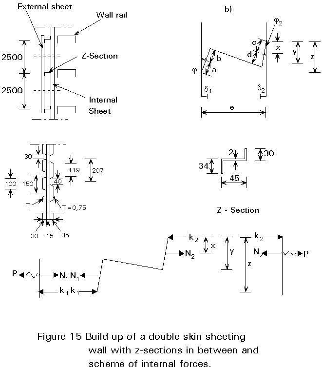
A symmetric loaded connection (by choosing a hat-section instead of a Z-section) will prevent prying forces occurring.
[1] Eurocode 3: Part 1.3: "Cold-Formed Thin Gauge Members and Sheeting" (in preparation).
|
TABLE 1 Global survey of application field for mechanical fasteners |
||||
|
Thin to Thick Steel |
Steel to Wood |
Thin to Thin Steel |
Fastener |
Remark |
|
X |
X |
Bolts M5 - M16 diameter |
||
|
X |
Self tapping screw 6,3 diameter with washer ³ 16mm diameter and 1mm thick with elastomer. |
|||
|
X |
X |
Hexagon head screw 6,3 diameter or 6,5 with washer ³ 16mm diameter and 1mm thick with elastomer. |
||
|
X |
|
X |
Self drilling screw with diameters: 4,22 or 4,8mm 5,5mm 6,3mm |
|
|
X |
Thread cutting screw 8mm diameter with washer ³ 16mm diameter and 1mm thick with or without elastomer |
|||
|
X |
Blind rivets with diameters: 4,0mm, 4,8mm, 6,4mm |
|||
|
X |
Shot fired pins |
|||
|
X |
Seam locking |
|||
|
TABLE 2 Requirements for connections in thin-walled structures |
|
Structural requirements: 1. Strength 2. Stiffness 3. Deformation capacity |
|
Non-structural requirements: 1. Economic aspects, such as:
2. Durability, which depends on:
3. Watertightness 4. Aesthetics |