ESDEP WG 16
STRUCTURAL SYSTEMS: REFURBISHMENT
To present new methods for the inspection and assessment of old steel bridges.
Lecture 12.10: Basics of Fracture Mechanics
Lecture 12.11: Stress Analysis of Cracked Bodies
Lecture 12.12: Determination of Stress Intensity Factors
Lecture 16.1: General Introduction to Refurbishment
A majority of existing steel bridges for road and rail are riveted structures built in the last century.
Many of these old bridges have been repaired or strengthened several times following damage in the World Wars or due to changes of service requirements. The safety of these bridges for modern traffic loads throughout their remaining service life needs to be considered.
This paper presents new methods for the inspection and assessment of old steel bridges in relation to their material toughness. These methods provide an overall view of residual safety and service life. They include the assessment of strengthening to improve static strength and resistance to brittle fracture.
The fracture mechanics-based verification procedures have been simplified so that the assessment can be carried out as easily as conventional strength checks. The procedures are illustrated by a numerical example.
Guidelines for the design of strengthening measures are given.
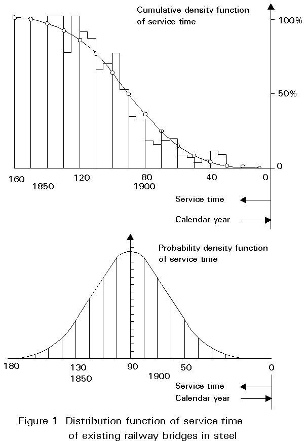
A majority of existing steel bridges for road and rail are riveted structures built in the last century. Figure 1 gives an example for the distribution of the service life of the railway bridges of the Deutsche Bundesbahn (German Federal Railway).
Many of these old bridges have been repaired or strengthened several times after damage in the World Wars or due to changes of service requirements. The safety of these bridges for modern traffic loads throughout their remaining service life needs to be considered.
This paper describes a procedure for determining the residual safety and service life of old steel bridges and presents a basis for economic decisions regarding further strengthening or replacement by a new bridge.
The procedure is illustrated by examples of bridges in Eastern Germany.
The questions to be answered for old steel bridges are as follows:
Studies of many bridges have shown that new methods of bridge and material inspection are necessary and that a quantitive assessment of safety is only possible when conventional strength checks are complemented by an assessment of material toughness based on fracture mechanics. These new methods are described below.
An assessment of old steel bridges includes a general conventional safety check of all structural parts and connections for modern load conditions to identify risks related to stability, strength or fatigue and any critical elements where, due to undetected cracks or damage, a failure could induce a complete collapse of the bridge.
These checks should normally be based on a complete set of drawings that give complete details of the structure and a static analysis that includes all information on material, cross-sections, dimensions, etc.
However, very often these documents are missing, incomplete or have not been updated and therefore need to be totally reproduced or amended.
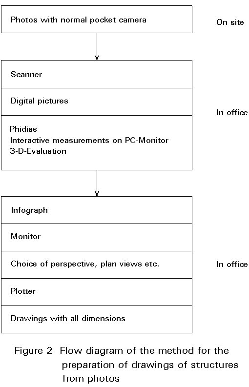
New methods based on the digital evaluation of photos have been developed for this purpose [1]. Figure 2 demonstrates the procedures for transferring expensive site measurements onto a PC in the office.
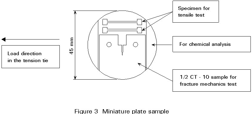
The process can also be used for checking the accuracy of existing drawings, recording damage, corrosion, etc. Local measurements, e.g. of residual plate thicknesses or other information, e.g. concerning the material, can be included. Material properties such as yield strength and tensile strength may be determined from miniature plate samples, which can be drilled from members adjacent to critical cross-sections without reducing their safety, Figure 3.
A structural member to be checked may, due to prior defects and undetected cracks, fail in different modes when subjected to tension loads, influencing the model for analysing the results. These failure modes may be best distinguished by the example of a plate in tension with a central crack, Figure 4, modelling a member with a hole with small cracks on both sides:
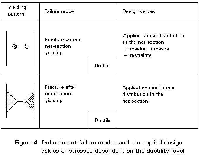
The failure mode is influenced mainly by the material, temperature, loading rate and shape of the structural member. For old steel bridges both failure modes 1 and 2 are relevant, as the assessment has to be carried out for design situations with low temperature, where the toughness values are low.
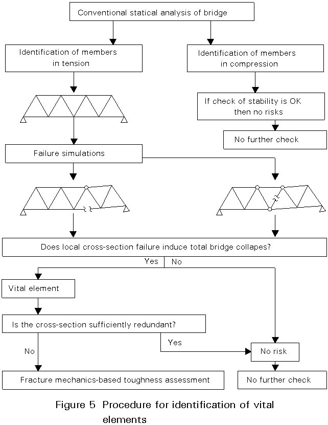
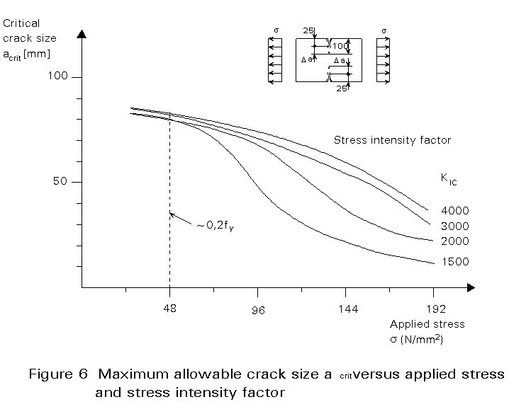
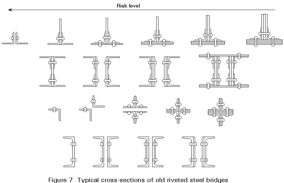
The toughness-related safety checks are restricted to risk areas with severe failure consequences. Therefore failure scenarios have to be established, where the consequences of failure of different bridge elements for different design situations are investigated, Figure 5. Vital elements are bridge elements whose failure would cause an immediate overall collapse. Vital elements loaded in tension have to be checked in view of toughness-controlled failure unless their cross-sections are so lightly stressed (s < 0,20 fy), see Figure 6, or are sufficiently redundant, see Figure 7, that they do not produce risks. Sufficient redundancy is assumed to be available when crack affected parts of the cross-section may fail without the yield strength being exceeded in the remaining parts of the cross-section.
The check should be based on several loading cases with combinations of selfweight, traffic loads (including dynamic impact) and temperature, which can be based on probabilistic approaches. Residual stresses and restraints may also need to be included depending on the expected failure mode.
The toughness assessment requires assumptions concerning existing structural defects expressed in terms of initial cracks.
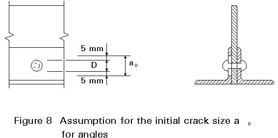
From fatigue tests on samples taken from old steel bridges it is known that cracks in old riveted bridges most probably initiate under the rivet heads propagating through the plate thickness and the widths of the outer plates [2].
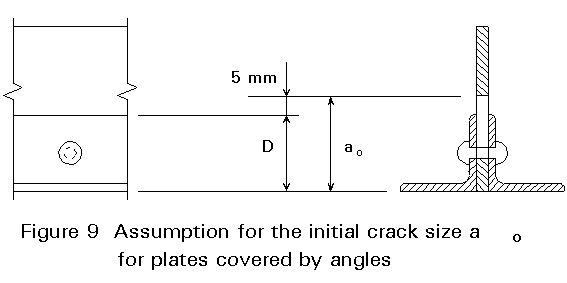
Hence it is assumed that on both sides of a rivet hole initial cracks may have formed that have just reached a sufficient size to be detectable. This limit is considered to be 5 mm beyond the rivet head, Figure 8. It has been proved by comparative studies that such a crack configuration may be modelled by a single crack with the initial size ao = D + 2 ´ 5 mm only. Where cracks are assumed to initiate in plates covered by angles, see Figure 9, the initial crack size is based on a detectable crack size of 5 mm beyond the flanges of the angle.
For a given loading case, true stress-strain curve and crack condition, e.g. for the initial crack size ao in a vital element, a fracture mechanics analysis based on a crack driving force Jappl may be calculated using handbooks or by FEM [4], see Figure 10. The curve Jappl-sappl determines whether the applied stresses lead to net section yielding (Jappl > Jyield) or not (Jappl < Jyield).
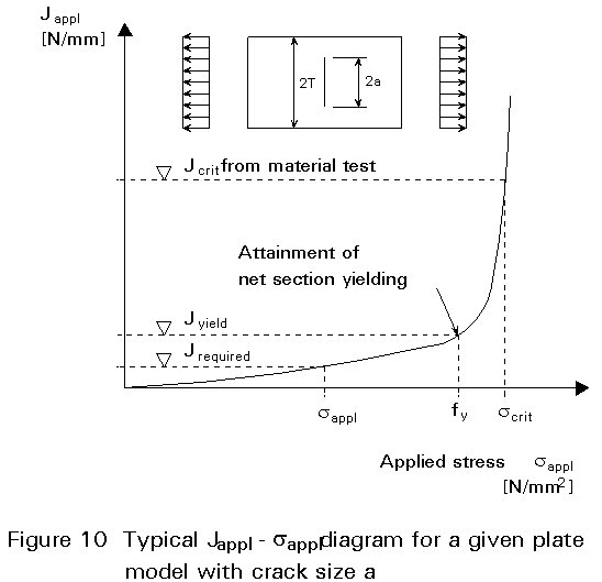
From the miniature plate samples, Figure 3, 1/2 CT-10 samples can be manufactured, from which the crack extension resistance Jcrit may be determined for a given temperature. This value may be compared with Jappl in the toughness safety verification:
Jappl £ Jcrit
see Figure 10.
If Jappl, calculated for the initial crack size ao, is smaller than Jcrit, it can be concluded that cracks with detectable sizes can be sustained without catastrophic consequences and no sudden collapse can be expected if the bridge is adequately inspected. If this check fails, the member has to be strengthened or replaced before the next cold season (because of loss of toughness at low temperatures).
The critical crack size acrit may be determined by iteration to satisfy the condition which, by definition, leads to failure, see Figure 11. From the position of Jyield in this diagram it can be established whether failure will occur before or after net section yielding and the design stresses to be included can hence be identified, see Figure 4.
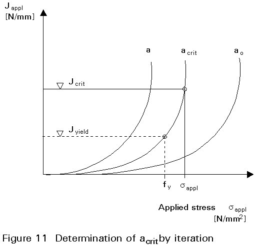
The different Da = acrit - ao is a measure of the minimum service time from the detection of cracks until failure. It should be at least as long as the time interval tinsp between two inspections.
To verify that this minimum service time is sufficient, the crack propagation time tp is calculated from the Paris equation using information on the magnitude and intensity of traffic, see Figure 12.

If
tinsp£ tp
no further actions are necessary. Otherwise either the inspection intervals must be reduced or the member must be strengthened to increase tp.
When the check tinsp £ tp is satisfied it may be concluded that, provided inspections are concluded at the critical locations of the vital elements at safe intervals:
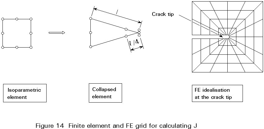
The J-Integral as a description of the material toughness [4,5] is defined by :
J = ![]() , see Figure 13.
, see Figure 13.
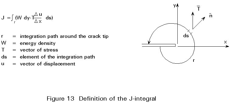
It provides a numerical measure of safety related to toughness and can be taken from handbooks or calculated by FEM with special grids of collapsed iso-parametric elements, Figure 14. The Jcrit-values may be determined by experiment in suitable laboratories.
The reliability of the J-Integral checking procedure for predicting failure loads of large scale members has been proved by large scale element tests [6,7].
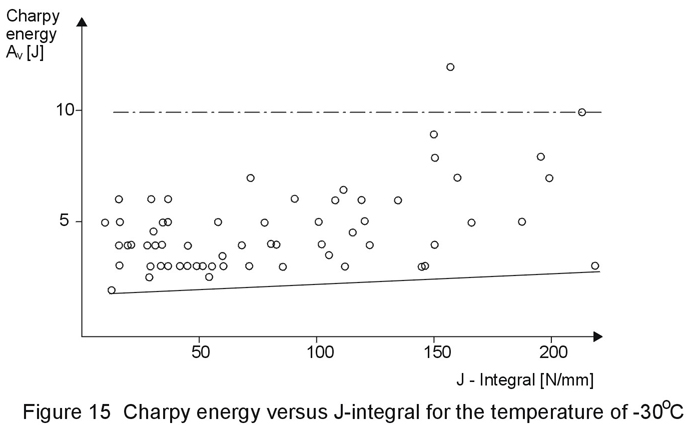
The results of the conventional Charpy test cannot be used for a quantitive safety assessment. Figure 15 shows the values of the Charpy-energy versus the values of the J-Integral for a temperature of -30ºC. It is evident that all values of the Charpy-energy are in the lower band, whereas the J-Integral values vary between low and high values. In view of the low costs of Charpy energy tests a correlation would be very useful but so far has not been found.
The iterative process needed for calculating acrit with the J-Integral concept as indicated in section 4 is rather time-consuming, expensive and appears suitable for fracture-mechanics experts only.
Therefore a simplified form of the method has been developed enabling toughness checks to be performed as easily as conventional strength checks.
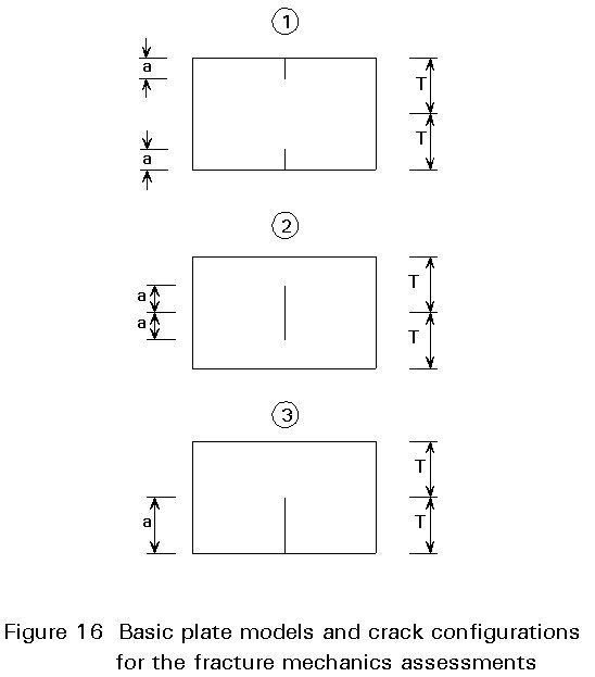
This simplified method has been developed in [8] by modifying the CEGB-R6 method for three basic plate models with initial crack configurations, see Figure16. By these modifications analytical expressions for acrit depending on the stress level d = s/fy, the plate width T, and the value of Jcrit can be found. By applying correction functions which give best fit approaches to the results of FEM calculations for typical situations, equations for acrit have been developed. These equations give conservative values of acrit which are sufficiently accurate and indicate whether failure is associated with net section yielding or not; Figure 17 gives graphical results for a basic model.

To explain how these basic plate models can be applied to actual structures, a guide has been developed based on FEM calculations as illustrated in Figure 18.

This figure also indicates the maximum crack that may limit acrit according to the results of fatigue tests.
As the basic plate models used for calculating acrit can also be used for calculating the number of cycles N(tp) in the minimum service time tp, design aids for determining N(tp) as a function of Ds, the plate width T and the difference Da = acrit - ao have also been developed. Figure 19 gives an example.
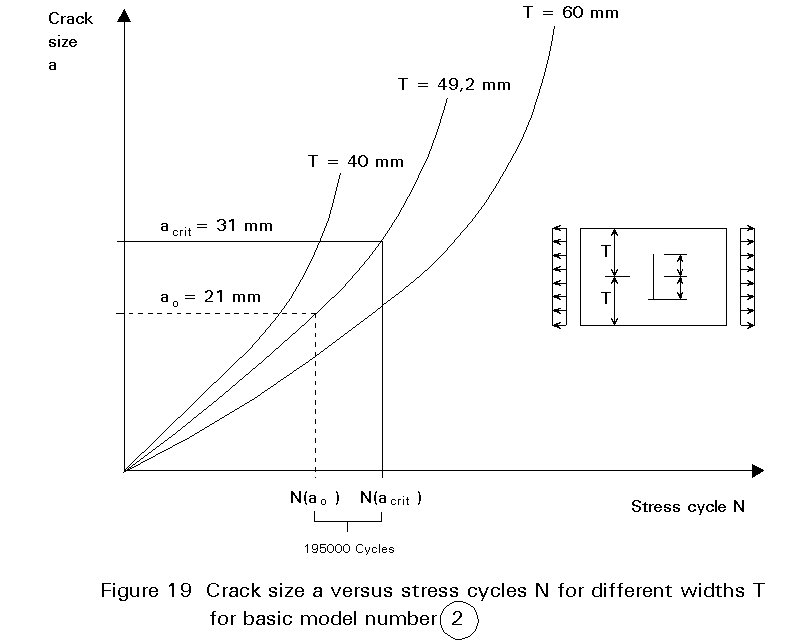
N(tp) can be found as
N(tp) = Nacrit - Nao
For the example in Figure 20 the following steps may be applied:
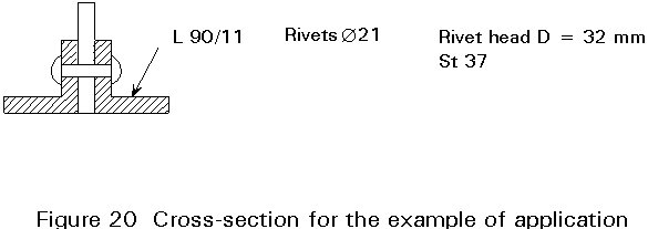
1.1 Material toughness (measured at -30°C) Jc = 10 N/mm
Yield strength fy = 240 N/mm2
1.2 Stresses s = sG+Q + sRes = 94 N/mm2
Stress ranges Ds = 47 N/mm2
1.3 Basic plate model (Figure 17) T = 1,1 ´ 90/2 = 49,2mmInitial crack size ao = (32 + 10)/2 = 21mm
Max a max a = 90/2 = 45mm
2. Determination of acrit2.1 Stress state d = 94/240 = 0,39
2.2 acrit (Figure 17) acrit = 27+(35 - 27)9,5/20 = 31 £ max a
3. Determination of the minimum service time
Figure 19 Nao = 4,256 ´ 106 cycles
Nacrit = 4,452 ´ 106 cycles
________________________________
N (tp) = 196000 cycles
Annual no. of cycles 51000 cycles
Minimum service time tp = 195000/51000 = 3,8a
Inspection interval tinsp = 3,0a
tinsp < tp fulfilled!
If the minimum service time N(tp) is less than the inspection interval Ninsp, the required additional cross-section DArequ can be determined by
where Anet is the available old cross-section area and m = 3.
An alternative is to assume the total old cross-section is susceptible to brittle failure and to supplement it by
D
A = max F / fywhich, in case of brittle failure, would take the total force. The minimum value DA may be applied.
A typical example of a strengthening detail is given in Figure 21.
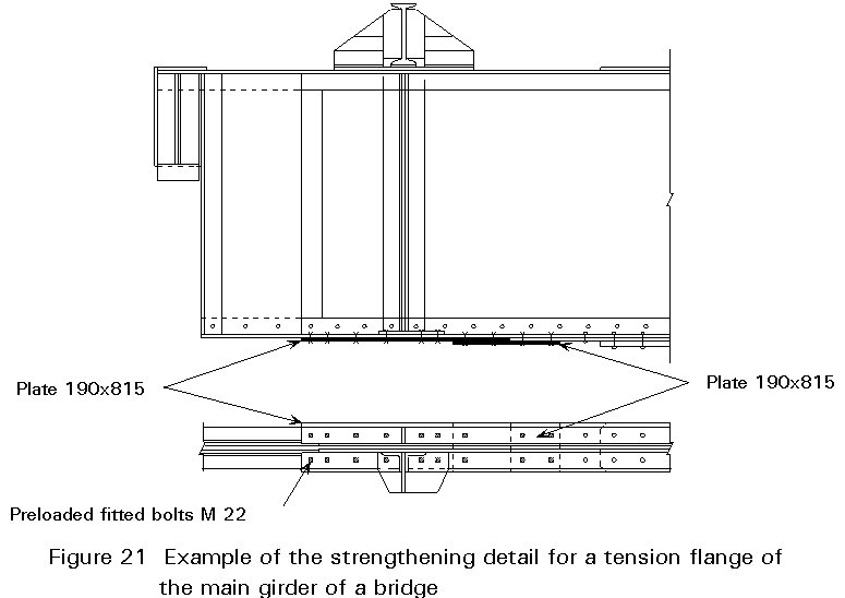
The fasteners for the connection of the strengthening plates should be fitted bolts (preferably preloaded to avoid the loosening of nuts and to improve the fatigue resistance), injection bolts [9] or coned bolts [10].
Previous experience of bridge checks suggests the following combination of minimum values for the material toughness and the yield strength of old riveted steel bridges.
Jc = 10 N/mm
fy = 280 N/mm2
A toughness assessment of an old bridge with these material values has proved to be conservative. If all checks are positive, no additional sampling is necessary. If not, sampling can be restricted to those critical members in tension where the conservative safety check is not satisfied.
[1] Benning, W., Effkemann, Ch., PHIDIAS - ein photogrammetrisch interaktives digitales Auswertesystem für den Nahbereich. ZPF-Zeitschrift für Photogrammetrie und Fernerkennung 3/1991.
[2] Brühweiler, E., Essais de Fatigue sur des Poutres a Tripplis Double en per Puddle. Publication ICOM 159/1986.
[3] Bild, J., Beitrag zur Anwendung der Bruchmechanik bei der Lösung von Sicherheitsproblemen im Stahlbau, Diss. RWTH Aachen, 1988.
[4] Rice, J.R. and Tracey, D.M., J. Mech. Phys. Solids 17, pa. 201-217,1969.
[5] Cherepanov, G.P., Crack propagation in continuous media. PMM Vol. 31, Nor. 3/1967, pp. 476-488.
[6] Dahl, W., Dormagen, D., Ehrhardt, H., Hesse, W., Twickler, R., Anwendung bruchmechanischer Konzepte auf das Versagensverhalten von Großplatten. Nucl. Eng. and Design, Vol. 87/1985, pp. 83-88.
[7] Ehrhardt, H., Untersuchungen zum Einfluß unterschiedlicher Fehlergeometrien auf das Versagensverhalten von Stahl auf der Grundlage von Großzugversuchen. Diss. RWTH Aachen, 1988.
[8] Hensen, W., Grundlagen für die Beurteilung der Weiterverwendung alter Stahlbrücken. Diss. RWTH Aachen, 1992.
[9] Gresnigt, A.M., Injection bolts in structural members. Researching 1991, Delft.
[10] Wuppertaler Stadtwerke AG, Patent für konische Bolzen mit metrischen Gewinden. Wuppertal 1990.