ESDEP WG 12
FATIGUE
To introduce the basic concepts of linear elastic fracture mechanics.
None.
Lecture 12.11: Stress Analysis of Cracked Bodies
Lecture 12.12: Determination of Stress Intensity Factors
Lecture 12.13: Fracture Mechanics Applied to Fatigue
Lecture 12.15: Fracture Mechanics Applied to Fitness for Purpose
The lecture describes the origins of fracture mechanics treatments based on strain energy concepts and the link to modern treatments based on crack tip stress analysis and the stress intensity factor. The effects of finite crack and component geometry are described together with the effects of small scale yielding and plasticity. The lecture concludes with a brief statement of the significance of the stress intensity factor.
Standard design methods for engineering structures and components under static loading are usually based on avoiding failure by yielding/plastic collapse or buckling. The derivation of loading resistance is based on conventional solid mechanics theories of stress analysis. Conventional design procedures against fatigue failure are based on experimental results for particular geometric details and materials. None of these procedures are capable of allowing for the effects of severe stress concentrations or crack-like flaws. The presence of such flaws is more or less inevitable to some extent in practical fabrications.
The modes of failure which are most affected by the presence of crack-like flaws are fracture and fatigue. The study of the effects of cracks on local stress and strain fields in the neighbourhood of the crack tip and the consequent effect on failure is the subject of fracture mechanics. The application of fracture mechanics methods allows analyses to be carried out to predict the effects of flaws on failure in a wide range of geometries to give complementary information to that obtained from experimental testing. For fatigue of welded structures the performance is significantly affected by the tiny flaws inherent to welding. Fracture mechanics analyses can be very helpful in predicting the effects of geometrical variations on basic fatigue behaviour.
Fracture mechanics methods are particularly useful in making fitness for purpose assessments of the effects of flaws, and for helping to decide on inspection procedures for fabricated structures and acceptance levels for any flaws which may be found during such inspections.
The origins of modern fracture mechanics go back to the work of A A Griffith [1] in 1920 investigating the strength of glass. Griffith used the linear elastic stress analysis solution for the stresses around an elliptical hole in a plate subject to uniform tension. He allowed the ellipse to degenerate to a crack and derived an expression for the energy released when an element of material at the end of the crack fractured to give incremental extension of the crack. He then suggested that, if the energy released was greater than the surface tension or cohesive force energy which had been holding the element together, then the situation was unstable, and continued unstable crack extension (i.e. fracture) would occur.
Griffith's expression for the change in strain energy from a plate with no crack to a plate with a crack length of 2a was:
U = -s2p2a2/E (1)
His expression for the strain energy release rate (now known as crack extension force), for a crack of length 2a in an infinite plate of unit thickness under uniform tension was given by:
![]() (2)
(2)
Griffith suggested that an existing crack would propagate unstably if the strain energy release rate, G, exceeded the energy required to create new fracture surfaces, 2g da, for crack growth da at each end of the crack, where g is the surface tension for glass. Hence he suggested that fracture would occur when:
s2pa/E ³ 2g (3)
i.e. at a critical value of the strain energy release rate Gc. Using this approach Griffith was able to explain that the reason that the observed strength of glass was much lower than theoretical estimates linked to the modulus was due to the presence of inherent tiny crack-like flaws in the material.
Irwin [2], and Orowan [3,4], extended original concepts of energy to create new surfaces, to include work of plastic deformation prior to fracture, provided the disturbance to the overall elastic stress field was small.
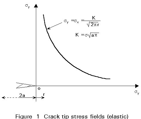
Irwin, used classical stress analysis methods (see Lecture 12.12) to investigate the detailed stress distributions near to the crack tip. Based on the complex stress function approach of Westergaard, Irwin showed that the elastic stress field in the neighbourhood of the crack tip (see Figure 1) was given by:
s
x =s
y =t
xy =It should be noted that these stress distributions are inversely proportional to the square root of distance from the crack tip. At the crack tip itself, (r = 0), the stress distributions predict infinite stresses, but this is an idealised situation, known as a stress singularity, resulting from the assumption of elastic behaviour without any limiting failure criterion. On the plane of the crack, (q = 0, y = 0) the shear stress is zero and the direct stress components are given by:
s
x = sy =The term s ![]() is dependent only on the applied stress and crack size, and defines the gradient of stress with inverse square root of distance away from the singularity at the crack tip. The term s
is dependent only on the applied stress and crack size, and defines the gradient of stress with inverse square root of distance away from the singularity at the crack tip. The term s ![]() was defined by Irwin as the stress intensity factor and given the symbol K. It should be noted that K is not a stress concentration factor, and that K has dimensions and units of stress x
was defined by Irwin as the stress intensity factor and given the symbol K. It should be noted that K is not a stress concentration factor, and that K has dimensions and units of stress x ![]() . Although the definition of stress intensity factor as K=s
. Although the definition of stress intensity factor as K=s ![]() is the one generally used for the case of a central crack in an infinite plate subject to remote tension, there are some papers in the literature where an alternative definition has been adopted without the p, namely K=s
is the one generally used for the case of a central crack in an infinite plate subject to remote tension, there are some papers in the literature where an alternative definition has been adopted without the p, namely K=s ![]() , and care must be taken to check which definition is being used in any particular case. In these notes the Irwin definition of K = s
, and care must be taken to check which definition is being used in any particular case. In these notes the Irwin definition of K = s ![]() is used throughout.
is used throughout.
It is very important to recognise that the stress singularity and stress intensity factor which dominate the stress field at the crack tip are features of tension loading which arise because tension forces cannot be transferred across the free surfaces of the crack and are redistributed around the ends of the crack in a non-uniform manner. When compression loading is applied to the cracked plate, if the crack surfaces are in contact, forces can be transmitted directly through the crack so that there is no requirement for redistribution and hence no stress singularity and the stress intensity factor is zero. This has important consequences when fatigue loading is applied to a cracked component.
Irwin showed that the stress intensity factor K was directly related to Griffith's crack extension force (or strain energy release rate) by the following expressions:
K2 = EG (plane stress) (8)
K2 = EG/(1 - n2) (plane strain) (9)
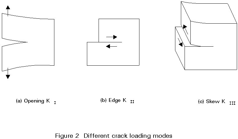
The description of the stress intensity factor given above is based on the simple case of an infinite plate with a central crack of length 2a subject to remote tension stress. This mode of loading is known as Mode 1 and the stress intensity factor resulting from this loading is strictly K1. There are two other forms of loading which produce a similar effect of a stress singularity because forces cannot be transmitted across the free surfaces of a crack. These forms are shear loadings parallel to the crack surfaces either in the plane of the plate, also known as edge sliding, (Mode II stress intensity factor KII), or perpendicular to the plane of the plate, also known as skew sliding or antiplane strain, (Mode III stress intensity factor KIII). These three different forms of loading are shown in Figure 2. In practice in structural components there may be combinations of the different modes to consider.
Another important case is that of a crack subject to internal pressure loading within the crack. For the notional case of a through-thickness crack in an infinite plate subject to internal pressure p, the stress intensity factor is given by:
K = p ![]() (10)
(10)
In the above considerations the crack has been a complete separation throughout the thickness of the plate and its geometry has been defined by the crack length 2a. In practice cracks in structural components may occur in a number of different forms. These forms are conveniently summarised for fracture mechanics analysis purposes in three categories, namely, through-thickness, part-thickness surface breaking, and part-thickness embedded cracks. A case of special importance is that of an elliptical crack embedded in an infinite body and subject to remote tension stress s as shown in Figure 3.
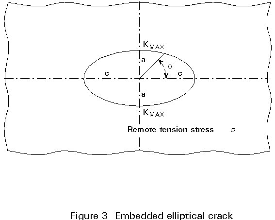
Irwin obtained an analytical solution for the stress distribution in the neighbourhood of the crack and found that a stress singularity occurred all round the perimeter of the crack front characterised by the stress intensity factor, but the magnitude of the stress intensity factor varied around the crack front. Irwin's solution for the variation of K around the crack was as follows:
 (11)
(11)
where a, c, f, are as shown in Figure 3, and E(f) is the elliptical integral:
E(f) =  (12)
(12)
The maximum value of the stress intensity factor occurs at the ends of the minor axis for this solution under uniform tension loading. The ratio of the height of the crack (2a) to the length of the crack (2c) is known as the aspect ratio. As this ratio decreases the solution for the elliptical embedded crack tends to a value K=s![]() , i.e. the same expression as for the central through-thickness crack of length 2a but with the elliptical crack having a height of 2a. Thus, for an embedded crack of this shape under tension loading, the dimension of the crack which has the greatest effect on the stress intensity factor in the height. Once the length is greater than about ten times the height, further increases in length make little or no difference to the K value unless they affect the cross-section area. For an embedded circular crack, the Irwin solution for the elliptical crack reduces to the same as the "penny shaped crack" case of Sneddon, i.e.
, i.e. the same expression as for the central through-thickness crack of length 2a but with the elliptical crack having a height of 2a. Thus, for an embedded crack of this shape under tension loading, the dimension of the crack which has the greatest effect on the stress intensity factor in the height. Once the length is greater than about ten times the height, further increases in length make little or no difference to the K value unless they affect the cross-section area. For an embedded circular crack, the Irwin solution for the elliptical crack reduces to the same as the "penny shaped crack" case of Sneddon, i.e.
K = ![]() (13)
(13)
Irwin applied similar arguments to derive the stress intensity factor for semi-elliptical surface cracks in a semi-infinite body with remote tension stress s as shown in Figure 4.
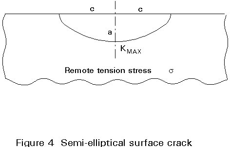
He suggested that this must be effectively one half of the elliptical embedded crack case divided on a plane of symmetry, but with a free surface correction factor. The result for the semi-elliptical surface crack is therefore:
 (14)
(14)
Again, as for the embedded elliptical crack case, it is the crack height which has the major effect on the maximum stress intensity factor. This maximum occurs at the end of the minor axis, i.e. the deepest point, for tension loading.
It should be noted that under applied bending stresses the variation of the stress intensity factor around the perimeter of the crack is different from the tension loading case. The maximum value can then occur at the ends of the crack depending on the aspect ratio.
The results described above for effects of crack shape are for the case of a body of infinite size. In practice there are also effects of finite size brought about by the proximity of boundaries or free surfaces. The effect has already been seen for the case of a semi-elliptical surface crack compared to the embedded elliptical crack where a free surface correction factor was included in Equation (14).
An important effect arises when the crack affects the net cross-section area either in the case of a through-thickness crack in a plate of finite width, or in the case of remaining ligaments between the crack front and a free surface for part-thickness cracks. The free surface and finite width corrections apply to all bodies of finite geometry. In general these correction factors can only be determined by numerical methods or experimental techniques as discussed in later lectures. There is also an effect of yielding in real materials leading to a further correction factor for small amounts of plasticity as discussed in the next section of this lecture.
The general form of the stress intensity factor for remote tension stresses s applied to part-thickness elliptical or semi-elliptical cracks can be written as:
K = ![]() (15)
(15)
where:
MD is the finite width and thickness correction factors
MS is the free surface correction factor
MP is a correction for local plasticity at the crack tip (discussed in Lecture 12.12)
MG is a correction for local stress concentration
E (f) is the elliptic integral dependant on crack shape aspect ratio.
The overall correction factors for finite geometry are dependent on the type of stressing. Solutions have been obtained by numerical methods for a range of part thickness elliptical crack shapes, subject to tension stresses sm and to bending stresses sb. It is usually possible to approximate actual stress fields by a combination of direct and bending stress components. The results can be presented as parametric equations or families of curves for coefficients Mm and Mb against a/t for different aspect ratios a/c or a/2c, where the expression for the stress intensity factor K value is given by:
K = (Mm sm - Mb sb) ![]() (16)
(16)
where Q is a crack shape parameter based on the elliptical integral E(f).
It should be noted that the Mm and Mb values vary around the perimeter of the crack, and the parametric equations include a term for position around the crack front. The most accurate results published openly at present appear to be those due to Newman and Raju in a series of papers, although there a number of stress intensity factor handbooks now available.
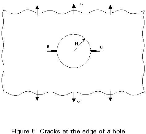
A further important effect is that of stress concentration regions at which a crack may lie. For example, fatigue cracks often develop from initial stress concentration regions and grow through a changing stress field. Two important examples of this kind are cracks at the edge of holes and cracks at the toe of welded joints. The case of cracks at the edge of a hole was solved by Bowie and is shown in Figure 5. For cracks which are small compared to the radius of the hole, the cracks behave as if they are surface cracks in a uniform stress field equal to three times the remote tension stress since the stress concentration factor at the edge of the hole in the absence of the crack is three. For cracks which are large compared to the radius of the hole, the two cracks behave as a single crack of total length equal to the sum of the two individual cracks plus the diameter of the hole.
In the case of cracks at the toe of welded joints, the stress intensity factor can be expressed by the use of a magnification factor Mx times the result which would be obtained for a crack of the same geometry subject to the same loading but without the stress concentration effect of the weld present. This case is discussed further in Lectures 12.13.
A convenient way to express the effects of all the coefficients/correction factors which can affect the stress intensity factor is to combine them all together into a single term generally know as the Y factor. This leads to the following overall expression for the stress intensity factor:
K = Y s ![]() (17)
(17)
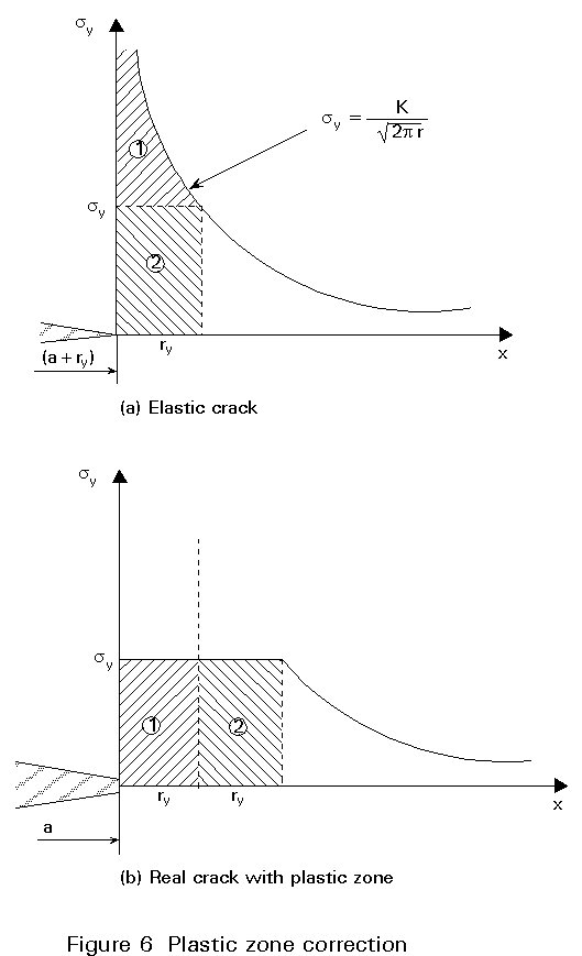
In real materials used for structural purposes, such as structural steels, the infinite stresses predicted by elastic theory at a crack tip are relieved by the occurrence of yielding. A first approximation to the size of the plastic zone at a crack tip is given by finding the distance ry from the crack tip at which the elastic stress level is equal to the yield strength. This distance is given by:
ry =  (18)
(18)
Limiting the stress at the crack tip to the yield strength means that the load bearing capacity on the crack plane is changed. This change leads to a redistribution of stresses locally. The effect of the redistribution is that for limited plasticity, (ry<<a), the real crack with plastic zone is equivalent to a crack in an elastic material of length 2(a + ry), as shown in Figure 6. The concept of 'plastic zone corrections' to elastic stress fields at cracks is useful as a limited extension to linear elastic fracture mechanics, but the effects of any more extensive plasticity have to be taken into account by different types of analysis such as crack tip opening displacement (CTOD) or J contour integral methods.
For the small scale yielding situation, substituting the modified equivalent crack length 2(a + ry) for 2a in the stress intensity factor formula for a central crack in an infinite plate gives the following plastic zone correction formula:
K =  (19)
(19)
It has been seen that, for components stressed in tension or bending, the stress field near to a crack tip under elastic conditions is predicted to be a singularity following an inverse square root relationship with distance from the crack tip, with the strength of this singularity described by the stress intensity factor. Furthermore in real materials the singularity is relieved by local yielding and the size of the plastic zone is directly related to the stress intensity factor. Since the whole of the stress and displacement field near to the crack tip is controlled by the stress intensity factor it would be reasonable to expect that any modes of failure which depend on reaching some critical stress, strain or displacement condition at the crack tip will be described by a critical level of the stress intensity factor. The two modes of failure most affected by the presence of cracks are fracture and fatigue. It will be seen in later lectures that the stress intensity factor is a most useful parameter for determining the effects of cracks on these modes of failure.
[1] Griffith, A.A. 'The phenomena of rupture and flow in solids', Phil. Trans. Roy. Soc. 1921 A221, 163.
[2] Irwin, G.R. 'Fracture dynamics', in Fracturing of metals ASM Cleveland, 1948.
[3] Orowan, E. 'Fracture and strength of solids', Rep. Prog. Phys. 1949 12, 185.
[4] Orowan, E. 'Energy criteria of fracture', Weld. J. Res. Suppl. 1955 20, 157s.