ESDEP WG 12
FATIGUE
To assist with an understanding of the proper detail category and of the importance of detail execution. To present an insight into the significance of details from the study of individual cases.
None.
Lecture 12.1: Basic Introduction to Fatigue
Lecture 12.8 Basic Fatigue Design Concepts in Eurocode 3
Based on Chapter 9 of Eurocode 3, Part 1, this Lecture presents an examination of typical structural details in an imaginary bridge structure. This enables a designer to compare various details when designing a structure, and to be aware of specific fabrication requirements. It also enables the designer to decide the proper category of details for calculations of fatigue strength.
In Lecture 12.1 the basic concept of classifying structural details into categories depending on their fatigue resistance is introduced. Each category is defined by the design constant stress range which can be endured with adequate reliability for 2 ´ 106 cycles (e.g. a category 112 detail would endure 2 ´ 106 cycles of 112 N/mm² with an adequate degree of reliability). For each such category, fatigue strength curves (commonly referred to as "S-N" curves) are presented in Figs. 9.6.1, 9.6.2, 9.6.3 and 9.7.1 of Eurocode 3 Part 1. These curves provide a complete relationship between the stress range and endurance for each category.
A large (but necessarily limited) selection of structural details is illustrated in Chapter 9 (Section 9.8, Tables 9.8.1 to 9.8.7) of Eurocode 3 Part 1, together with the categories (determined from a large number of test results ) into which the details fit. The first task facing a designer checking a structure for fatigue is therefore the determination of the appropriate categories for the details of the structure. This may appear a comparatively trivial task, but in practice a civil engineering structure will contain a large number of structural details which may be prone to fatigue cracking; problems in allocating appropriate categories can arise from several sources, the most important of which are:
a. The actual details may not correspond exactly to any of those described in Eurocode 3 Part 1.
b. The detailed geometry, stress distribution and direction, workmanship, etc. may alter the basic category.
In order to assist a designer in selecting the correct detail category, this lecture presents a case study of a particular civil engineering structure, and shows how the details can be classified.
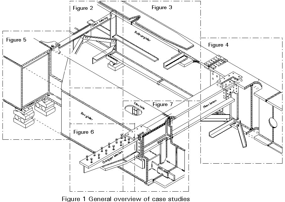
The case study comprises an imaginary steel bridge, as shown in an exploded isometric view in Figure 1. In order to illustrate as many different details as possible, two forms of construction are shown with a box girder on the left hand side and a braced plate girder on the right hand side. Furthermore, there are differences between the two sides in bearing arrangement, connection of cross girders, etc. It is not suggested that these arrangements, nor even some of the details, are necessarily representative of good design practice; they are presented for the purpose of illustrating a point of discussion.
This imaginary structure is then subdivided as shown in Figure 1 into several close-up details in Figures 2 - 7, which in some cases are further subdivided where necessary for clarity. The detailed figures indicate the direction of principal stress, and the potential crack location and direction; the category into which the detail should be classified is shown as a number in a circle beside the detail. Occasionally the slope of the S-N curve departs from the "standard" value of 3; this is indicated where "m=.." is noted beside the detail category.
In a number of instances, where indicated by a small letter inside a square, additional notes are required to enlarge on some important factors which may affect the classification. This may happen where some guidance is needed in respect of the calculation of the design stress or of the fabrication procedure or requirements. Sometimes more than one form of cracking may occur at a single site, or more than one factor may contribute to cracking. Such matters are also covered, where relevant, by notes.
Where a detail in the case study does not correspond closely to a specified detail in Chapter 9 of Eurocode 3 Part 1, the category quoted is based on that specified in other codes or derived from tests known to the authors of this lecture; when this knowledge has been used it is described in a note. It is also expected that the Tables of details will be extended or modified for steel bridges when Eurocode 3 Part 2 is published in due course, and in a few cases reference is made to what may appear there. Furthermore, even when a detail is ostensibly covered by Chapter 9, it is sometimes necessary to take into account particular design aspects or fabrication procedures when determining the category. Such considerations (many of which are outside the scope of this lecture, but are covered in other lectures) are:
a. Design Stress Evaluation
The importance of knowing the direction of the principal stress fluctuation cannot be over-emphasised; in most cases this is straightforward, but sometimes it is made more difficult by the uncertainty of prediction of exactly where the crack will occur and in what direction it may propagate. Since the stresses to be used must be based on elastic calculations, account must be taken of secondary stresses which in complex details may be difficult to quantify.
b. The Quality of the Preparation of a Joint
The fit-up of a joint, and the method of terminating a butt weld (extensions or run-off plates) can all affect the category, especially for site welds.
c. The Accessibility of a Location for Welding
Welds with difficult access are frequently of lesser quality and are more prone to defects and hence fatigue than those which are easily accessible.
d. Proper specification of parent metal and welding consumables.
e. Operating Procedure
For example, butt welds without backing flats are of a better category than those with, provided that full penetration can be obtained. There are differences between permanent and temporary backing flats.
f. The Profile and Surface Finish of the Weld
Welds with excessive "reinforcement" or rough surface generally perform less well in fatigue than if they are ground level and smooth.
g. The Acceptance Criteria for Weld Quality
In order to achieve the category in Chapter 9 of Eurocode 3 Part 1 certain minimum standards of quality in regard to defect shape, location, type and size must be attained.
h. Improvement Techniques for Welded Joints
These include grinding, peening, gas tungsten arc remelting, etc. They are intended to improve the category above that shown in Chapter 9, and are described in detail in Lecture 12.5.
j. Weld Defect Assessment and Repair
If the defects in a weld are greater than are permitted for a particular category, the weld may, rather than being rejected, either be downgraded (if the fluctuations in stresses are low) or repaired. Repair requires special care in specification and execution; not infrequently a repaired weld is worse than the original weld. Whatever repair procedure is used, the final category should be determined with caution.
FIGURE 2
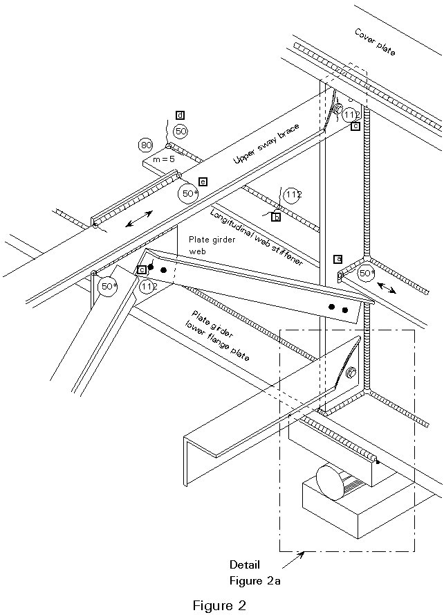
a. This detail is not given explicitly in Chapter 9; it should generally be avoided (it is usually better, and probably easier, to detail the longitudinal stiffeners passing through "mouseholes" in the transverse stiffeners). The nearest detail in Chapter 9 is shown under cruciform joints, where root cracking of the weld should be checked as category 36*, and of the plate from the weld toe as shown as category 71. The category shown of 50* results from other work.
b. The category of 112 shown is the "standard" one for automatic fillet welding carried out from both sides, but containing stop-start positions (Table 9.8.2 (3) or (4)). If it contained no stop-start positions it could be upgraded to category 125, or even 140 if a specialist inspection shows that the welds are free from significant flaws; conversely, if the fillet were placed manually, it would be downgraded to category 100. It is likely that Eurocode 3 Part 2 will exclude the higher categories of 125 and 140 for this detail since the necessary quality of workmanship is impractical for bridge structures.
c. Stresses should be calculated using the gross section for slip resistant connections, or the net section for all other connections (Table 9.8.1 (6) or (7)). The effects of eccentricity in the connection should be taken into account when calculating the stresses in a single-sided connection.
d. This detail (at the termination of a longitudinal stiffener) may be treated for cracking in the main plate as a long (>100m) longitudinal attachment within the width of a plate with a non-load carrying weld (Table 9.8.4 (1)). Eurocode 3 Part 2 will probably add the requirement that the weld should be carried round the end of the stiffener. Note that the weld may also require checking in shear, with the stress range calculated from the weld throat area.
e. The gusset plate attached as shown to the leg of the angle may be treated as a cover plate wider than the flange (with the leg of the angle representing the flange) (Table 9.8.5 (5)). Provided all plate thicknesses are 20mm or less, this is category 50* for cracking in the angle; this reduces to 36* if thicknesses exceed 20mm. The weld should be continued down the leg of the angle, and ground to remove undercut if necessary.
FIGURE 2a
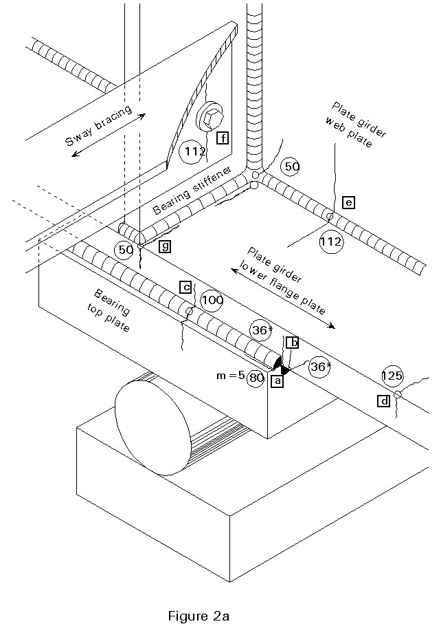
a & b These details show how cracks may grow in different directions in an area of complex geometry and stress distribution. Considerations are similar to Figure 2, note e, but the bearing plate > 20mm thick and so the category for plate cracking is reduced to 36* (Table 9.8.5 (5)).
c. See Figure 2, note b; as the weld to the bearing plate will almost certainly be placed manually, the lower category of 100 is used (Table 9.8.2 (5) or (6).
d. The category of the plate edge depends on the method of production; if it is a rolled flat the category could be increased to 160, or if machine flame cut with subsequent machining to 140. The indicated category of 125 is for a machine flame cut edge without subsequent machining, although Eurocode 3 Part 2 will probably specify the quality of the cut edges (Table 9.8.1 (5)). It should contain no repairs by weld infill.
e. As for Figure 2, note b.
f. As for Figure 2, note c.
g. The category of this weld has been reduced from the 71 or 80 shown for web stiffeners (Table 9.8.4 (4)) since the stiffener is shown flush with the edge of the plate.
FIGURE 3
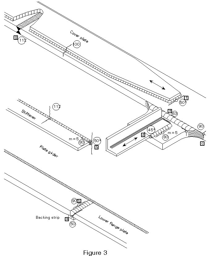
a. This is a rather poor detail, since because of the taper in the flange a good fit cannot be guaranteed above the backing flat; hence the low category of 50 (Table 9.8.3 (11)).
b. At the top of the butt weld, provided the "reinforcement" does not exceed 0.1 times the width of the weld bead, the category is 90 (Table 9.8.3 (4)); up to 0.2 it would be 80 (Table 9.8.3 (7)). Run off pieces should also be used. (If the weld is ground flush the category could be 125 or higher). Normally there would be little point in making the category of the top surface much higher than that of the bottom, unless the eccentricity arising from the change of plate thickness results in a higher stress range at the top.
c. The comparatively high category of this weld is only true for a gusset plate with a generous radius as drawn ( > 150mm, and also > (width of main plate)/3) (Table 9.8.4 (2)). The radius has to be formed by initial machining or gas cutting, with subsequent grinding of the weld area parallel to the direction of stress. If the radius < (width of main plate)/6 the category falls to 45*, and between the two limits above to 71.
d. This is a straightforward application of the detail of Table 9.8.5 (4). It should be noted that the weld should be held back 10mm from the end of the gusset. As it is a single sided connection, the effects of eccentricity should be considered.
e. This is again a straightforward application, this time of Table 9.8.5 (3). The calculation of the stress in the main plate requires care, and in a single sided application as shown may have to allow for eccentricity.
f. This is a standard "bad" detail for increasing the area of a plate and the category is given in Table 9.8.5 (5). The plates in the example are not thicker than 20mm so the category is 50*; above this thickness the category is reduced to 36*. Contrary to what may be thought, tapering the cover plate as shown, or rounding its end, does not, in itself, improve the detail; however, a special detail with tapering welds and chamfered cover plates, being developed by German Railways, may raise the category to 80. This may appear in Eurocode 3 Part 2.
g. This is a two sided butt weld, with the surface ground flush (Table 9.8.3 (1)). Significant quality control and inspection is required to permit the use of this high category.
h. As for Figure 2, note d.
FIGURE 4
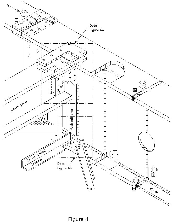
a. This is a butt weld, without backing flat and ground flush, between plates of different thickness (Table 9.8.3 (3)). Provided the difference in thickness is taken up by tapering the thicker member with a slope of not greater than 1:4, this still qualifies as a category 112 weld.
b. As Figure 3, note g.
c. As Figure 3, note g, but it is a single sided weld without backing flat and because very high quality of execution and inspection is specified, the category can be raised to 125 (Table 9.8.3 (1)).
d. As for Figure 2, note c, but as the connection is double sided no eccentricity occurs.
FIGURE 4a
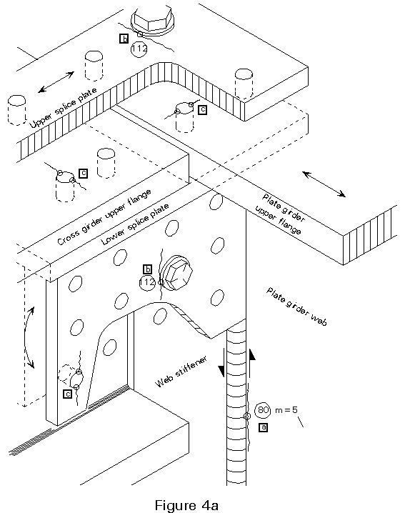
a. This is the standard detail for fillet welds in shear (Table 9.8.5 (6)). The stress range should be calculated from the weld throat area.
b. As for Figure 2, note c, but as the connection is double sided no eccentricity occurs. Note that crack begins from edge of washer.
c. As for Figure 2, note c, but as the connection is double sided no eccentricity occurs. Note carefully that direction of crack is related to direction of stress.
FIGURE 4b
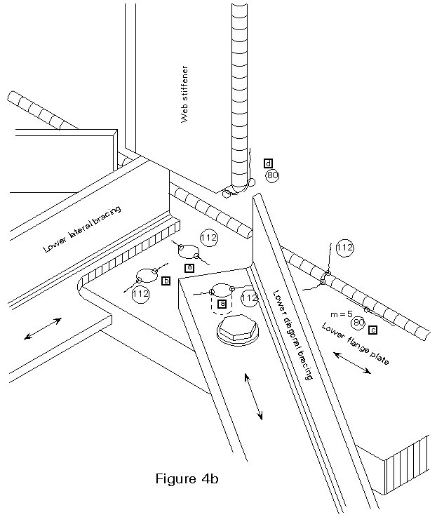
a & b Are both as for Figure 2, note c, but note that the direction of stress, and hence the direction of cracking, may differ from hole to hole.
c. As for Figure 4a, note a.
d. This is the standard detail of Table 9.8.4 (4) (left hand diagram), provided the thickness of the stiffener does not exceed 12mm. (If it does exceed 12mm, the category is reduced to 71). Note that the stiffener should terminate at least 10mm above the flange, and the weld should be returned round the bottom of the stiffener. Some recent evidence suggests that out-of-plane flexure of the web plate at the termination of the stiffener could degrade this detail, but research continues on it.
FIGURE 5
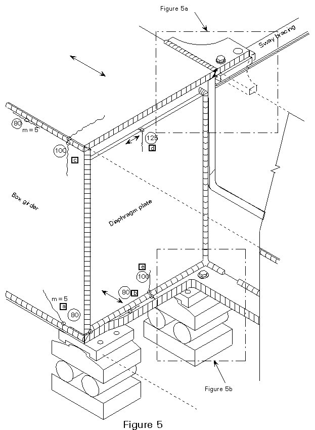
a. As for Figure 4a, note a. Note crack propagating across direction of principal tensile stress.
b. This is the standard detail for the welding of diaphragms in box girders to the webs and flanges, where the diaphragm thickness is not greater than 12 mm (Table 9.8.4 (5)). If the thickness were greater the category would be reduced to 71.
c. This is the standard detail for corner welds of box girders (Table 9.8.2(6)). Note that a good fit between flange and web is essential, so that a one sided weld can be placed without blow through. In certain forms of construction and loading this weld is also prone to bending about its longitudinal axis due either to local traffic loading or distortional effects in the box girder. It is virtually impossible to give a category for such effects, and considerable experience is necessary.
d. As for Figure 2a, note d.
e. See Figure 2, note b. As the weld will be placed manually, it is category 100 (Table 9.8.2 (5)).
FIGURE 5a
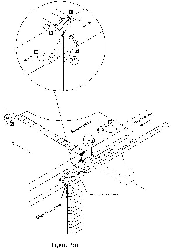
a. This weld is being stressed by flexure of the web plate and is not readily classifiable from the details in Eurocode 3 Part 1. It is similar, however, to the long attachment, Table 9.8.4 (1), and it is probably safe to use that category (50*).
b. As for Figure 2, note c.
c. See Figure 3, note c. Because the main plate (the flange of the box girder) is wide, the radius of the gusset plate is more severe than it appears and hence the weld falls into the lowest category, for this detail, of 45*.
d, e & f These welds are very difficult to categorise and are not covered explicitly in Eurocode 3 Part 1. Furthermore, although the direction of stress is shown by arrows on the detail, the welds may also be subjected to flexural effects in the web and flange. Considerable caution should therefore be used in attempting to classify them.
Detail d can be thought of as an incomplete penetration butt weld placed from one side only (Table 9.8.3(8)), and hence classified as category 36*.
Details e and f are analogous to the cruciform detail, Table 9.8.5 (2), and so are category 36* as far as cracking from the root is concerned. Cracking in the parent plate from the toe of the weld may be checked at the higher category of 71 in the gusset plate (detail e, Table 9.8.5 (1)) or 90 in the flange (detail f, Table 9.8.3 (4), provided the special requirements in the table are met).
FIGURE 5b
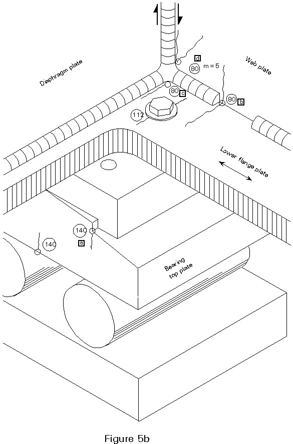
a. As this will be a machined plate, the high category of 140 may be used (Table 9.8.1 (4)). However, as there is a re-entrant corner, stress concentrations will occur and the magnified stresses should be used in making the check.
b. This is similar to the category at the end of lengths of intermittent fillet weld where the gap is less than 2.5 times the weld length (Table 9.8.2(8)). Hence the category may be taken as 80.
c. As for Figure 5, note b.
d. As for Figure 4a, note a. Note crack propagating across direction of principal tensile stress.
FIGURE 6
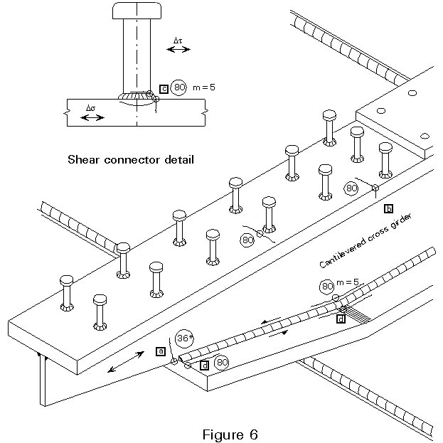
a. This detail is not classified in Eurocode 3 Part 1. It is clearly of a very low category and should not be used if the stress range is significant. It would appear appropriate to classify it as the lowest category available, 36*.
b. The effect of the shear connectors on the base plate is to cause a category 80 detail (Table 9,8.4 (6)).
c. The weld connecting the shear studs is classified in Table 9.8.5 (8) with the shear stress calculated on the nominal cross section of the stud. Further information on fatigue of studs is available in Eurocode 4.
d. As for Figure 4a, note a.
FIGURE 7
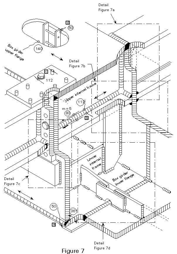
a. This detail represents a butt weld on a permanent backing flat, where the backing flat fillet weld terminates closer than 10mm from the plate edge (Table 9.8.3 (11)).
b. As for Figure 2, note b.
c. As for Figure 2, note c.
d. This connection is effectively a welded transverse attachment with a non-load carrying weld (Table 9.8.4(3)). However, the weld terminates at the plate edge, and so the detail is a worse category than in the table. Category 50 appears appropriate. It should be pointed out from this how an apparently minor, non-structural, detail can seriously degrade the fatigue capacity of the structure. If it has to be used, it should be positioned in an area of low stress fluctuation.
FIGURE 7a
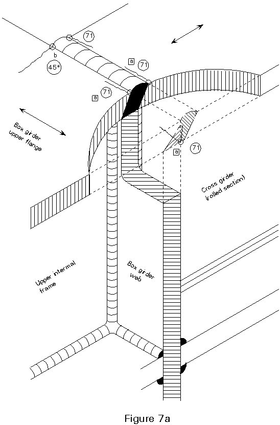
a. These welds are similar to those shown on Table 9.8.5 (1) for cracking in the parent plate from the toe of the weld in cruciform joints.
b. This detail is effectively a gusset with zero plan radius (Table 9.8.4 (2)) and so falls into category 45*.
FIGURE 7b
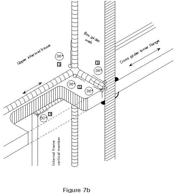
a. This is a detail which is not explicitly classified in Eurocode 3 Part 1. It is close to the cruciform detail (Table 9.8.5 (2)) but probably rather less severe. An appropriate category is 50*.
b. These welds are all effectively the worst possible cruciform details (Table 9.8.3 (2)). Note that if the welds are made of sufficiently large section to avoid root cracking there are other mechanisms which may govern.
FIGURE 7c
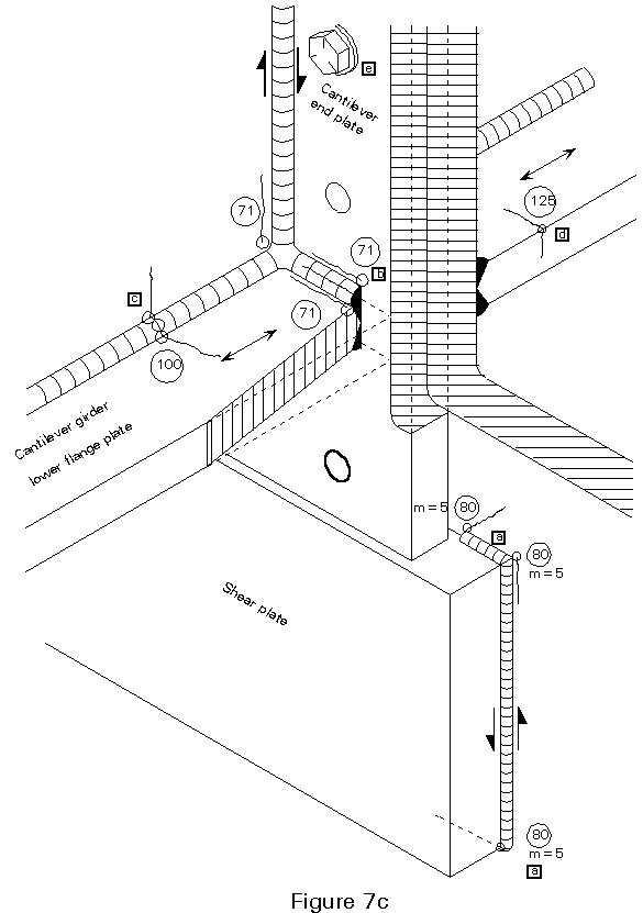
a. As for Figure 4a, note a. Note crack propagating across direction of principal tensile stress.
b. These welds are similar to those shown on Table 9.8.5 (1) for cracking in the parent plate from the toe of the weld in cruciform joints.
c. This weld is likely to be placed manually - see comments at note b for Figure 2.
d. As for Figure 2a, note d.
e. This detail is intended to represent what happens with a bolt in tension (Table 9.8.1 (8)) through an endplate. The category for the bolt itself is the low one of 36*, and the stress in tension in it should be calculated using its stress area. Account should also be taken of any prying action resulting from flexing of the endplate; it should be noted, however, that the stress range in the bolt may be reduced substantially by appropriate preloading. The crack position in the endplate shown on Figure 7c should also be checked under the flexural stresses resulting from prying action.
FIGURE 7d
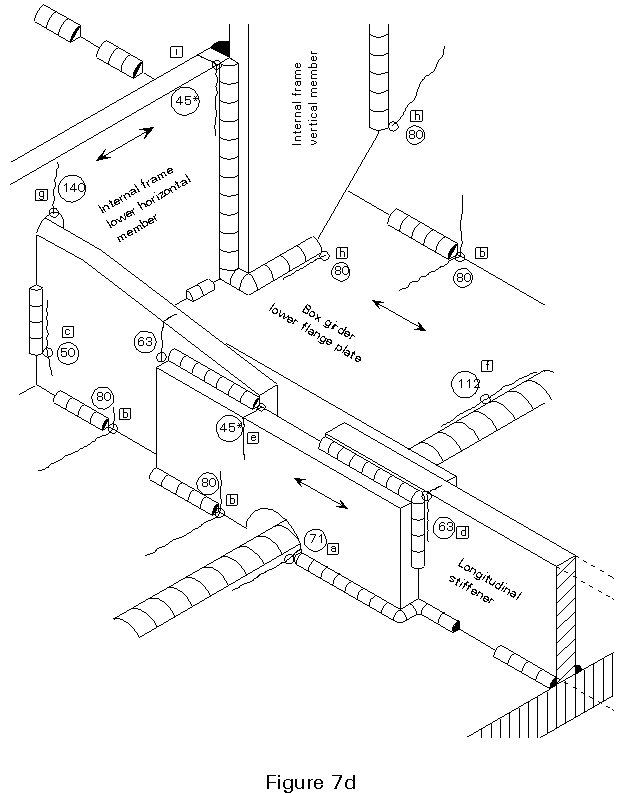
a. This is a straightforward instance of the detail for the ends of a continuous weld at a cope hole (Table 9.8.2 (9)).
b. This detail is a straightforward instance of the end of an intermittent fillet weld. Note that where it occurs close to (but not actually at) a cope hole, it permits use of the higher category of 80, compared with detail a above where terminating the weld actually at the cope hole requires use of category 71.
c. This detail is not explicitly covered in Eurocode 3 Part 1. The weld is non-load carrying, and hence there are some similarities with the detail shown in Table 9.8.4 (3). However, the "transverse attachment" is a load carrying plate, hence the detail is not fully appropriate. Tests have indicated a somewhat lower category (50) is reasonable.
d. This detail is equivalent to the standard one for cracking in the main plate at the end of a fillet welded lap joint (Table 9.8.5 (3)). Note the specified rule for the calculation of the stress in the main plate.
e. This detail is equivalent to the standard one for cracking in the lap plates in a fillet welded lap joint (Table 9.8.5 (4)). Note that the weld termination should be held back at least 10mm from the plate edge, and that shear cracking in the weld should also be checked according to Table 9.8.5 (7).
f. As for Figure 3, detail g.
g. Whilst this detail belongs in the relatively high category of 140 for a machine gas cut edge with all edge discontinuities removed (Table 9.8.1(4)), the stresses should be calculated using the appropriate stress concentration factor for the radius which is used.
h. This is the standard category for web stiffeners where the thickness of the stiffener does not exceed 12mm and the welds do not come within 10mm of a plate edge (Table 9.8.4 (4) and (5)).
i. Whilst this detail is not explicitly covered in Eurocode 3 Part 1, it shows a number of similarities to the "wide cover plate" detail of Table 9.8.5(5)). It is clear that a low category is appropriate, and 45* is proposed.