ESDEP WG 9
THIN-WALLED CONSTRUCTION
To introduce the different types of sheeting and to discuss test requirements and calculation methods for trapezoidal sheeting.
Lecture 9.1: Thin-Walled Members and Sheeting
Lecture 9.7: Application of Thin-Walled Construction
Worked Example 9.3: Trapezoidal Sheeting
Lecture 2.4: Steel Grades and Qualities
The lecture illustrates how the different types of sheeting are typically used in roof, floor and wall construction. Product development is discussed and the reasons for "design by testing" explained. Calculation procedures for design of trapezoidal sheeting are given involving checks on bending, shear, web crippling and bending/shear interaction at internal supports.
As discussed in Lecture 9.1, cold-formed sheeting can be developed not only to give adequate load bearing resistance but also to satisfy the functional requirements of the design. This aspect is now considered in more detail in relation to the common usage of cold-formed sheeting in roof, wall and floor structures.
Roof structures
Roof sheeting systems can be used for either "cold" or "warm" roofs as described below:
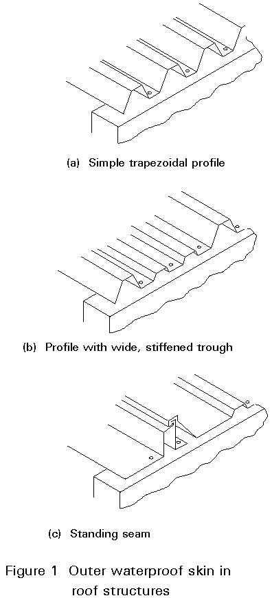
a) A "cold roof" has an outer waterproof skin with internal insulation if required (Figure 1). The main requirement of preventing penetration by rain water leads to shallow profiles with a sequence of wide and narrow flanges; sheets are fixed using fasteners applied to the crests of the corrugations or by means of clips (standing seam profiles). The use of few points of fastening means that the forces at these points are relatively high; for these types of profile spans are relatively small.
b) A "warm roof" (Figure 2) includes insulation and water proofing, and is built up using a load-bearing profile, insulation (mineral wool or plastic foam), and an outer layer, e.g. metal skin, as mentioned above.
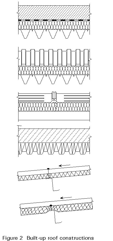
The load-bearing profiled sheeting in this type of roof normally has the wider flanges turned up in order to provide sufficient support for the insulation. Fasteners are placed in the bottom of the relatively narrow troughs. In this case, the tendency is towards longer spans, using more complex profiles provided with intermediate stiffeners.
Wall structures (Figure 3)
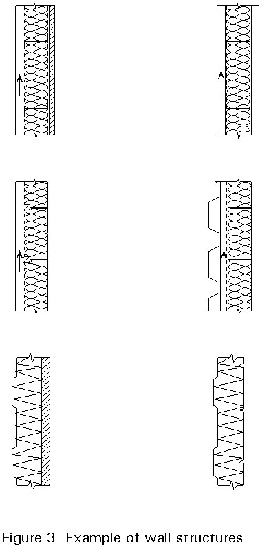
Wall structures comprise an outer skin of "architectural" sheeting of relatively small span, and a substructure which transmits the wind loading to the main building structure. The substructure can be a system of wall rails or horizontal deep profiles (cassettes) with integrated insulation. Another solution combines the load-bearing and protecting function in a "sandwich" panel built up by metal profiles of various shapes and a core of polyurethane.
Floor structures (Figure 4)
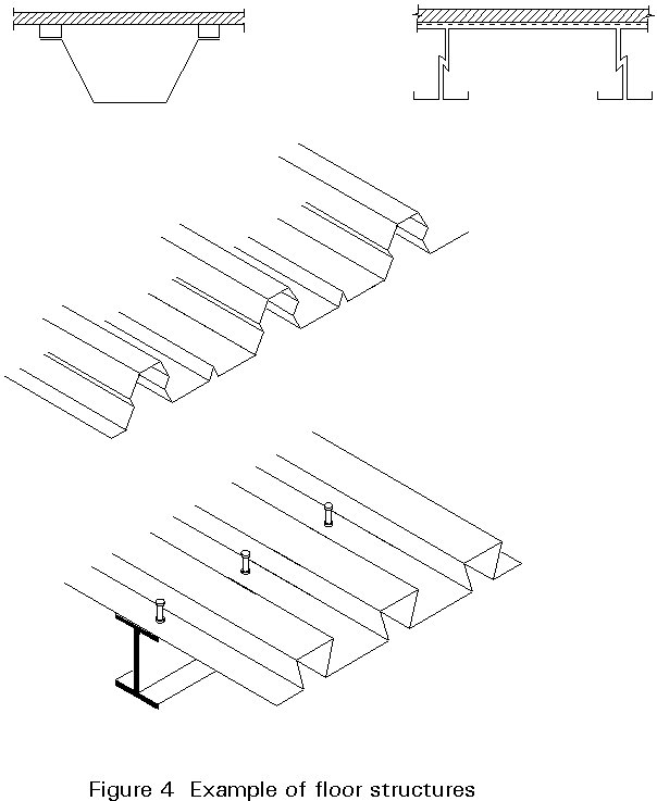
Floor structures have sheeting, e.g. trapezoidal sheeting or cassettes, as the load bearing part, either alone or in composite action with other materials such as board or plywood decking or cast in-situ concrete. In the first case, the composite action is provided by adhesives and mechanical fasteners, in the second by means of indentations and/or special shear studs.
Since bending moment resistance is the main requirement, the profiles selected for flooring purposes are similar to those for roof decking.
Design objectives
For trapezoidal sheeting with "normal" geometric properties of depth, width, stiffness and sheet thickness, design based on analytical expressions is possible (see Worked Example 3). Testing is required for profiles outside the defined range of geometrical properties and where composite action of other materials acting with the sheeting is to be assessed.
Because of the many types of sheeting available and the diverse functional requirements and loading conditions that apply, design is generally based on experimental investigations (except for trapezoidal sheeting where analytical methods can be used). This experimental approach is generally acceptable for mass produced products, where optimization of the shape of the profiles is a competitive need.
During the 1960's, more and more countries established their own production of trapezoidal sheeting and export of these products increased. As a consequence of increased competition and trade, product development quickly led to new types of profiles with intermediate stiffeners, higher material strength and geometrical improvements (see Figure 5). The developments all led to increase of load bearing resistance.
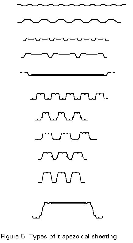
The product development, however, was based more on experience of the functional behaviour of the products than on analytical methods. The initial "design by testing", and subsequent growing understanding of the structural behaviour allowed analytical design methods to be developed; theoretical (semi-empirical) design formulae were then created based on the evaluation of test results. This type of interaction of analytical and experimental results occurs whenever special phenomena are responsible for uncertainties in the prediction of design resistance (ultimate limit state) or deformations (serviceability limit state).
Thousands of tests - as described below - have been carried out and evaluated, and design formulae have been developed which adequately predict the load bearing resistance of trapezoidal sheeting. However it is necessary to restrict design values to a relatively low level so that the design load resistance is somewhat lower than the actual resistance. This low level is necessary because a wide range of geometrical properties has to be covered by the design rules and, depending on the geometrical shape, different types of failure can occur.
Calculation procedures for trapezoidal sheeting are described in Section 3 below:
Types of testing (Figure 6)
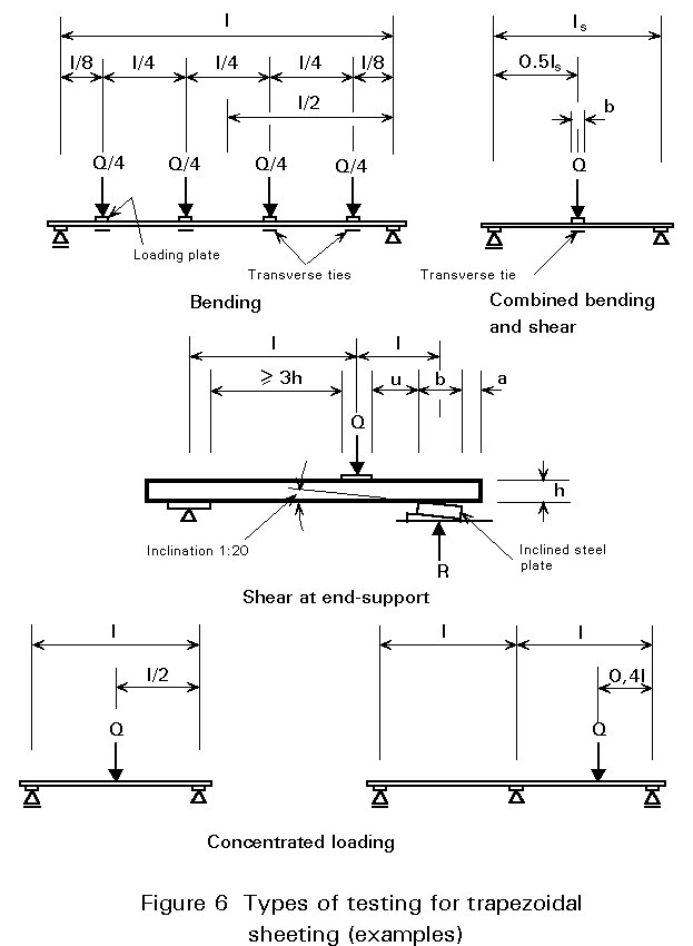
Testing may be required for optimization purposes or due to lack of appropriate analytical design methods; if necessary, tests may be carried out to ascertain the following:
Normally tests are performed under both gravity, e.g. dead weight and snow load, and uplift loading, i.e. wind suction; in addition, if the sheeting is unsymmetrical the loads are placed in two positions, depending on the application. Practical support and loading conditions are taken into account, which implies, for example, that for uplift loading the resistance of the fasteners and connections at the end and interior supports must be measured. More detailed information is presented in Part 1.3 of Eurocode 3 [1].
The tests should simulate the real behaviour of the sheeting under practical conditions. It is important that the testing equipment and the testing procedures are kept simple in order to achieve reliable and comparable results.
The rate of load application should usually be such that the stresses can be treated as quasi-static and be approximately equal in a test series. Furthermore an adequate number of load steps should be used in building up the load.
The load-bearing tests must be accompanied by standard tensile tests, using test specimens taken from the plane parts of the profiles. The load-bearing test results are then corrected with respect to the actual values of the core thickness (tf), yield strength (fyt) and the specified values (t, fy).
The corrected test result is derived from the actual test result as follows:
Rn = Rt(ff/fyt)a (t/tt)b
b = 1 for t ³ tt
b = 2 for t < tt
a = 0 for fy ³ fyt
a = 0,5 for fy < fyt if failure is caused by local buckling, otherwise a = 1
Using this procedure, the test results are transformed into values, with reference to nominal or specified values of sheet thickness and yield strength.
When designing sheeting the following checks should be carried out:
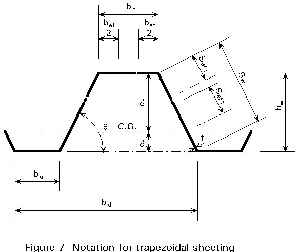
Design formulae for the above have been developed using the notation given in Figure 7.
Step 1: Check the section geometry complies with the appropriate limits, i.e. b/t £ 500, sw/t £ 500 (otherwise design by testing)
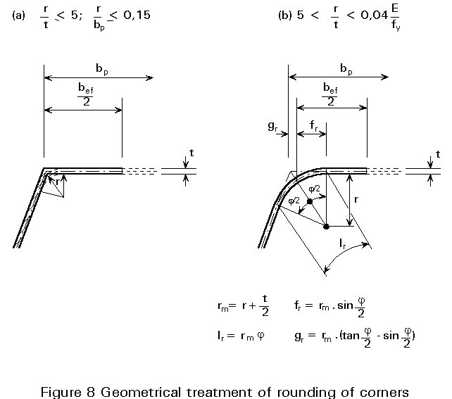
Step 2: Check whether rounding of corners can be ignored, i.e. r/t £ 5, r/bp £ 0,15 (otherwise use the section properties from Figure 8)
Step 3: Check the effect of flange curling (see 3.1.2)
Step 4: Check the effect of shear lag (see 3.1.3)
Step 5: Calculate the section values of the gross cross-section (Ag, Wg, Ig)
Step 6: Calculate the effect of intermediate stiffeners in flanges and webs (see 3.1.4)
Step 7: Calculate the section values of the effective cross-section (Aef, Wef, Ief) at ultimate limit state (for fy) and serviceability limit state (for sc < fy)
Step 8: Determine the moment resistance Mc,Rd = fy. Wef. Plasticity in the tension zone, (see 3.1.5) may also be taken into account. Determine the bending stiffness (Elef) at serviceability limit state.
The following sections 3.1.1 - 3.1.5 are only intended as an explanation; design formulae and procedures should be taken from the codes.
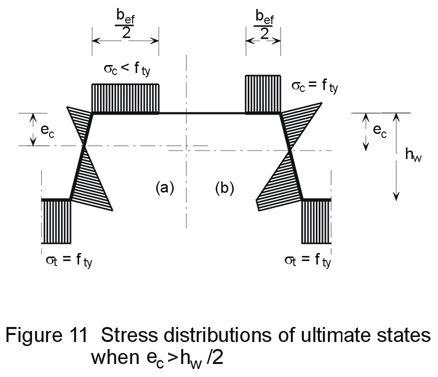
Normally it is assumed that the bending resistance (Mc,Rd) at the ultimate limit state can be calculated by assuming the stress in the compression zone is at yield (see Figure 11a). The effective width bef of the compression flange is calculated in the usual way. With a reduced compression flange (see Lecture 9.1), and the web treated as fully effective, the depth ec to the approximate position of the neutral axis is calculated. The effective portions of the compression zone of the web are then positioned as shown in Figure 7, having lengths given by:
Sef,1 = 0,76 . t![]()
Sef,2 = 1,5 Sef,1
where sc is the compressive stress at the flange level. The ultimate moment of resistance Mc may then be calculated for the doubly reduced cross-section with ec and et referred to the approximate neutral axis.
Due to the curvature of the sheeting, flanges of trapezoidal sheeting with high b/t ratios are prone to an inward deflection towards the neutral plane, caused by a radial component of tensile or compressive bending stresses. Normally this effect has only to be considered if the bp/t ratio is more than 250(sw/bp), where sw is the width of the web and bp the width of the flange. Approximate formulae for calculating the effect of flange curling, which in principle reduces the moment resistance, are given in the codes.
Shear lag is associated with wide flanges with relatively short span lengths (L/bp £ 20). Owing to the action of in-plane shear strain in the flanges, the longitudinal displacements in the parts of the flange remote from the webs lag behind those nearer the webs. As the stress distributions, due to shear lag, have similarities to those of local buckling, an effective width approach can be applied. Normally this phenomenon can be ignored for trapezoidal sheeting. For other cases appropriate design rules are given in the codes.
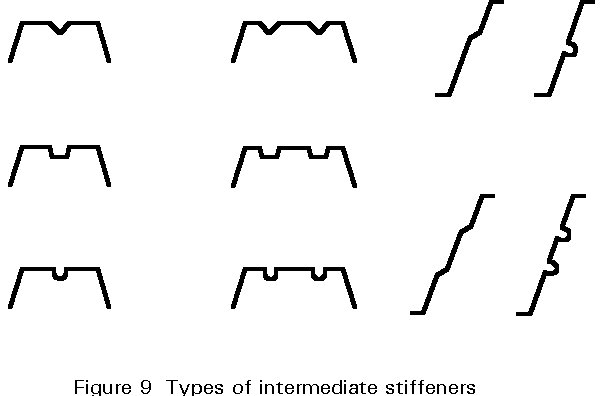
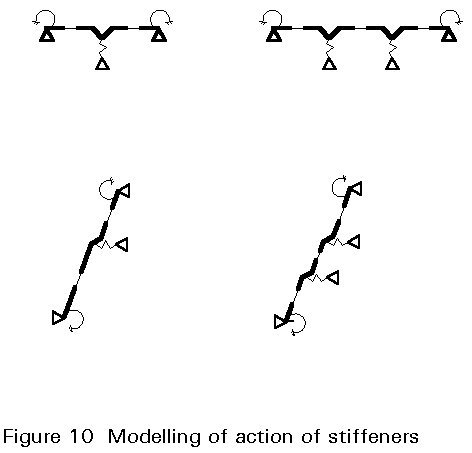
The design of profiles with stiffeners is not within the scope of this lecture, nor is it explicitly illustrated in Part 1.3 of Eurocode 3 [1]; such advanced profiles with intermediate stiffeners in flanges and/or webs are normally developed by manufacturers who will supply load resistance information derived from testing programmes. Intermediate stiffeners, as shown in Figure 9, can substantially increase the load-bearing resistance with respect to bending, shear and crippling as well as the stiffness (see Lecture 9.1). The basic idea is to reduce the flange width (b) and the web height (h) by means of supporting springs perpendicular to the plane elements (flanges and webs), where the spring stiffness depends on the flexibility of the elements and their boundary conditions (see Figure 10). The interaction of the elements, however, implies an iterative design procedure, resulting in increased effective section properties, compared to those of plane elements without stiffeners.
There are two cases of neutral axis position that should be considered:
If the neutral axis of the effective section is located closer to the compression flange than the tension flange, then tensile yield will occur first and plasticity of the tension zone may generally be utilized. According to Figure 11b, the equilibrium of a section under bending is given by:
Mp,Rd =Aefò zisc.dA/ gM (1)
and the position of the neutral axis can be derived from the equation:
Aefò s.dA = 0 (2)
If the neutral axis is located closer to the tension flange, then compression yielding occurs first. No plasticity is permitted. Hence, for a linear stress distribution (Figure 11a) without plasticity and for max sc £ fy, Equation (1) can be written as:
Mc,Rd = sc.Wef/gM (3)
where Wef is the section modulus of the effective cross-section.
Where plasticity in the tension zone of the effective cross-section occurs, the location of the neutral axis has to be determined by an iterative process.
The maximum shear stress in the web of trapezoidal sheeting is as follows:
w = 0,346 (sw/t) Ö(fy/E) (4)
It may be assumed that the shear stresses are uniformly distributed along the web, so that the design shear resistance along the web is given by the following:
Vw,Rd = tsp . sw . t/gM (5)
where:
tsp is taken from a
buckling curve for ![]() w > 0,8, or if
w > 0,8, or if ![]() w
£ 0,8, is equal to the maximum value
of 0,58 fy.
w
£ 0,8, is equal to the maximum value
of 0,58 fy.
Sw is the distance between the points of intersection of the system lines of the web and flanges.
t is the core thickness of the section.
If the web is provided with intermediate stiffeners, the design strength is increased.
This phenomenon, which is similar to that of shear buckling, is related to the stability of the web under concentrated loading (see also Lecture 9.1). It is, however more severe with respect to the load-bearing resistance of the sheeting since the post-critical bearing reserve is quickly exhausted if buckling occurs. This is especially true if the concentrated loading is accompanied by shear and bending stresses, as is usually the case. Formulae for the design resistance (Rd) are based on test results.
Among other parameters, the design resistance depends on the width of the sheeting support, i.e. the bearing length on the substructure. One means of avoiding the web crippling effects is to provide the sheeting with special support cleats, so that the support reaction is transmitted from the sheeting to the substructure by tension forces instead of compression.
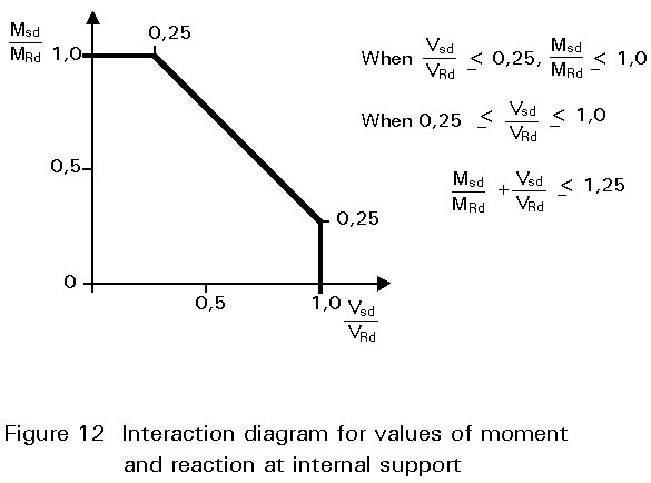
The load resistance of continuous sheeting greatly depends on its behaviour in the region of the intermediate support (see also Section 3.5) where the maximum bending moment occurs; the design resistance in this area must, therefore, also be checked. Interaction formulae which have been derived from a large number of test results (see Figure 12), show that interaction need not be taken into account if the actual support reaction or concentrated load is less than 25% of the design load; in this case the bending resistance can be fully utilized. In practice, the load ratio will often be above this limit, requiring a reduction in the bending resistance, as follows:
![]() (6)
(6)
where:
![]() (7)
(7)
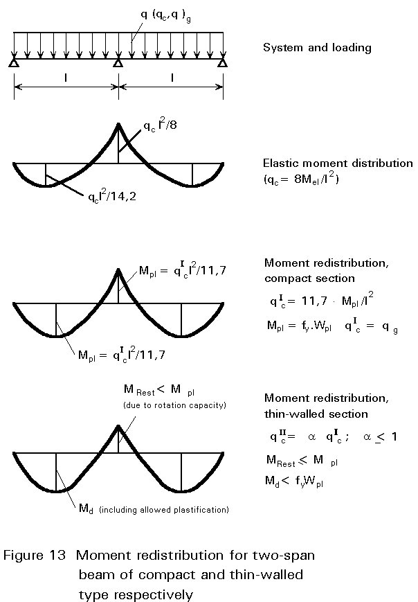
Continuous beams of compact (thick-walled) sections may be designed, as a rule, according to plastic hinge theory allowing moment redistribution by rotation of plastic hinges. For thin-walled sections with adequate rotational capacity the same method can be used; as a rule, however, the plastic capacity is limited by buckling phenomena and only part of the full plastic moment can be used for the moment redistribution. On the other hand, the rotational capacity provided by the "buckling hinges" may be sufficient for a new equilibrium state of the continuous beam to arise after buckling at the support has occurred (Figure 13). The moment redistribution must be investigated by tests, in which the rotational capacity with respect to the geometrical properties can be quantified.
Knowledge of the bending stiffness is important for calculating deflections at the serviceability limit state. As the section properties depend on the effective area, which is a function of the actual stresses, it is necessary to relate the moment of inertia to the appropriate stress level (sc < fy).
[1] Eurocode 3, Part 1.3: "Cold Formed Steel Sheeting and Members" CEN (in preparation).