ESDEP WG 9
THIN-WALLED CONSTRUCTION
To introduce the concept of stressed skin design and to discuss the practical applications of this method.
Lecture 7.11: Frames
Lecture 9.1: Thin-Walled Members and Sheeting
Lecture 9.4: Design Procedures for Sheeting
Worked Example 9.1: Stressed Skin Design
This lecture explains the contribution that panels of roofing, flooring and walls make to the resistance and stiffness of frameworks by virtue of their resistance and stiffness in shear ("shear diaphragms"). Procedures and tables for the calculation of the resistance and flexibility of diaphragms are given. The practical applications of stressed skin design are also discussed.
a = length of diaphragm in a direction perpendicular to the corrugations (mm)
A = cross-section area of longitudinal edge member (mm2)
b = depth of diaphragm in a direction parallel to the corrugations (mm)
c = overall shear flexibility of a diaphragm (mm/kN)
d = pitch of corrugations (mm)
E = modulus of elasticity of steel (205 kN/mm2)
fy = yield strength of steel in sheeting (kN/mm2)
Fp = design shear resistance of individual sheet/purlin fastener (kN) (see Table1)
Fs = design shear resistance of individual seam fastener (kN) (see Table 1)
Fsc = design shear resistance of individual sheet/shear connector fastener (kN) (see Table 1)
h = height of profile (mm)
k = frame flexibility (mm/kN)
K = sheeting constant (see Tables 4 and 5)
l = width of corrugation crest (mm)
L = span of diaphragm between braced frames (mm)
n = number of panels in the length of the diaphragm assembly
nb = number of sheet lengths within depth of diaphragm
nf = number of sheet/purlin fasteners per sheet width
np = number of purlins (edge + intermediate)
ns = number of seam fasteners per side lap (excluding those which pass through both sheets and the supporting purlin)
nsc = number of sheet/shear connector fasteners per end rafter
n1sc = number of sheet/shear connector fasteners per intermediate rafter
nsh = number of sheet widths per panel
p = pitch of sheet/purlin fasteners (mm)
q = distributed shear load on diaphragm (kN/mm)
sp = slip per sheet/purlin fastener per unit load (mm/kN) (see Table1)
ss = slip per seam fastener per unit load (mm/kN) (see Table1)
ssc = slip per sheet/shear connector fastener per unit load (mm/kN) (see Table1)
t = net sheet thickness, excluding galvanising and coating (mm)
V = applied shear force on diaphragm (kN)
V* = design shear resistance of diaphragm (kN)
Vcr = shear force on diaphragm to cause overall shear buckling (kN)
VR = resistance associated with a given failure mode or ultimate load (kN)
a
1, a2, a3 = factors to allow for intermediate purlins (see Table 3)a
4 = factor to allow for number of sheet lengths.For the case considered a4 = (1 + 0,3nb)
ß1,ß2 = factors to allow for the number of sheet/purlin fasteners per sheet width (see Table 2)
ß3 = distance between outermost fasteners across the sheet width divided by sheet width.
For sheeting (seam fasteners in the crests) ß3 = ![]()
For decking (seam fasteners in the troughs) ß3 = 1,0
D
= midspan deflection of a panel assembly (mm)u
= Poisson's ratio for steel (0,3)It has long been recognised that a building framework is considerably strengthened and stiffened once the roof, floors and walls have been added. Frame stresses and deflections calculated on the basis of the bare frame are usually quite different from the real values. By taking the cladding into account, the actual behaviour of the building can be predicted and usually worthwhile savings may be made in the costs of the frames.
The contribution that panels of roofing, flooring and side cladding make to the resistance and stiffness of frameworks is by virtue of their resistance and stiffness in shear, i.e. the resistance of rectangular panels to being deformed into parallelograms. Hence such panels are known as "shear diaphragms" or simply "diaphragms". In the United States, the design method which takes this effect into account is called "diaphragm design" whereas in Europe it is called "stressed skin design".
Profiled steel sheeting used as roof sheeting or decking, floor decking or side cladding, is very effective as a shear diaphragm. Provided it is positively attached to the secondary members and main frames by mechanical fasteners or welding, it is extremely reliable and predictable and may be confidently used as a structural component. Moreover, it has been verified by many full scale tests and proven by practical experience of many buildings designed on this basis.
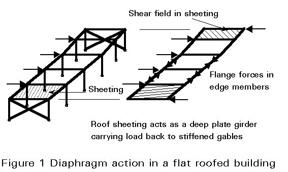
The principles of stressed skin design may be illustrated with reference to flat- roofed or pitched-roof buildings. In a flat-roofed building subjected to side load (Figure 1) each of the roof panels acts as a diaphragm taking load back to the gable ends which are stiffened in their own planes by bracing or sheeting.
In a pitched-roof building (Figure 2) under vertical or side load, there is a component of load down the roof slope so that the roof diaphragms tend to prevent the building from spreading or swaying. The flatter the roof pitch, the less effective the diaphragms are in resisting vertical load, but the more effective they are in resisting horizontal load.

The sheeting in Figures 1 and 2 acts in the roof such that the roof behaves like a deep plate girder. Under in-plane load, the end gables take the reactions, the sheeting acts as a web and takes the shear, and the edge members act as flanges and take the axial tension and compression. In no case does the sheeting help the frames to resist bending out of the plane of the sheeting.
If the frames of Figure 1 are pin-jointed, then the horizontal loads are resisted entirely by stressed skin action. In this case the structure must be adequately braced during erection and the sheeting panels must not be removed without proper consideration.
If the frames of Figure 1 have rigid joints, then the horizontal loads are shared between the frames and the diaphragms. In this case it is good practice for the frames alone to be designed to carry the full characteristic load without collapse, and for the completed stressed skin building to be designed to carry the full design load. The diaphragms then effectively provide the required load factor.
Stressed skin design should be used predominantly in low-rise buildings where the roof and floors can behave as a deep plate girder as shown in Figure 1. It should be noted that diaphragm action will always occur in a building,whether or not it is taken into account in design.
Benefits
Some of the benefits of stressed skin design are as follows:
a. Calculated frame stresses and deflections are usually much less than in the bare frame.
b. Calculated and observed stresses and deflections agree, so the design is more realistic.
c. Bracing in the plane of the roof is eliminated or frame sizes are reduced.
d. Frame details are standardised.
e. The method is particularly effective where lateral loads act only on one or two frames, e.g. cross surge from light overhead cranes.
f. By taking diaphragm action into account the actual forces on the cladding and fasteners can be calculated.
Conditions
In order for steel sheeting to act as a diaphragm the following conditions must be met:
a. End gables must be braced or sheeted.
b. Edge members must be provided to panels and these members and their connections must be designed to carry the flange forces.
c. Sheeting must be fastened to members with positive connections such as self drilling screws, cartridge fired pins or welding.
d. Seams between sheets must be fastened with positive connections.
e. Suitable structural connections must be provided to transmit diaphragm forces into the main framework.
f. It is recommended that the shear stress in the sheets be less than 25% of the ordinary bending stress in the sheets, so that if the sheets are corroded they will fail in bending long before the stressed skin building is endangered.
g. It is recommended that roof light openings should be less than 3% of the relevant roof area unless detailed calculations are made, in which case up to 15% may be allowed.
Restrictions
Buildings designed on stressed skin principles should normally be umbrella type structures rather than structures which carry fixed loads. In order to ensure the safety of the building at all times, the following restrictions should be placed on design:
a. Most of the load on the building should be applied via the sheeting itself, e.g. self weight, snow load, wind load.
b. If the sheeting is removed, most of the load will also be removed.
c. Sheeting should not be used for helping to resist other fixed loads, e.g.mechanical plant.
d. Sheeting must be regarded as a structural member and so must not be removed without proper consideration.
e. The calculations and drawings should clearly draw attention to the fact that the building is designed by stressed skin methods.
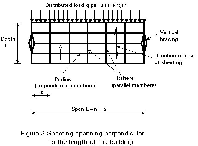
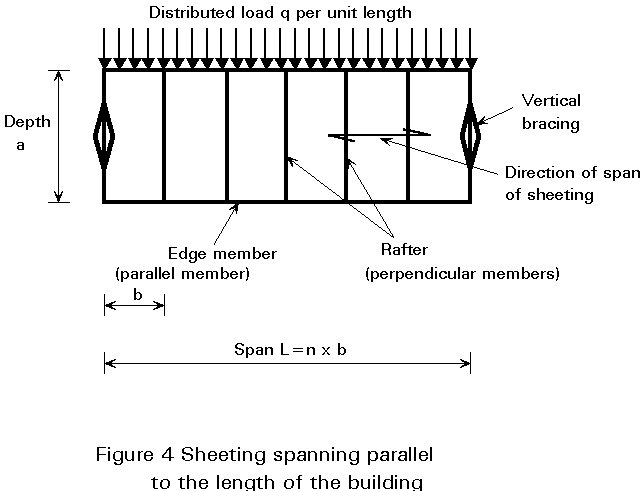
Sheeting may span perpendicular to the length of the building (Figure 3) or parallel to the length of the building (Figure 4). Whenever possible each panel of sheeting should be fastened on all four edge members since this gives the greatest diaphragm resistance and stiffness. If all members are not at the same level, "shear connectors" as shown in Figure 5 may be used to provide fastening on all four sides. If this is not possible, diaphragms may be fastened to purlins on two edges only provided that the end panels are fastened on their third side to the end gables. If sheeting is fastened only to the purlins, then the purlin/rafter connections at the intermediate rafters must be adequate to introduce the loads at these rafters into the diaphragm.
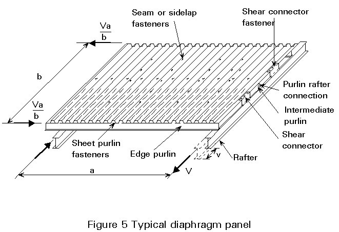
The typical diaphragm panel shown in Figure 5 is for sheeting spanning perpendicular to the length of the building. In calculating the shear resistance and flexibility of a panel, the design expressions refer to the direction parallel to the corrugations. For sheeting spanning parallel to the length of the building, a modification to the design expressions must be made. This modification is not considered in this lecture.
For a typical panel attached on all four sides as in Figure 5, the diaphragm resistance VR in the direction of the load V depends on the failure resistance of:
a. a line of seam fasteners
or
b. a line of shear connector fasteners.
These two failure modes, being ductile, are taken as the design criteria. Any other failure mode, being less ductile, is required to have a considerably greater resistance than the lesser of the above calculated values. Such other modes include failure at the sheet/purlin fasteners, failure of the sheeting due to shear buckling, end collapse of the sheeting profile and failure of the edge members under tension or compression. Because of the low level of shear stress in the sheeting, it is not normally necessary to take diaphragm action into account when designing sheeting for its primary function in bending.
For a typical panel attached to purlins on two edges only (Figure 5 without the shear connectors) an additional design criterion is the tearing resistance of the end sheet/purlin fasteners in the sheeting in an intermediate panel. This case is not considered in this lecture.
It is not possible in one lecture to derive and explain the design expressions used, but see [1]; instead, the design expressions are presented in this section, and a guide to their use is given in the worked example.
Important note: in the following expressions, design values are used throughout, so that there is no further need to incorporate a material factor.
For a panel attached on all four sides, the expressions for diaphragm resistance are as follows:
Seam resistance
![]() (1)
(1)
Shear connector fastener resistance (at end gables)
![]() (2)
(2)
Shear connector fastener resistance (at internal rafters)
![]() (3)
(3)
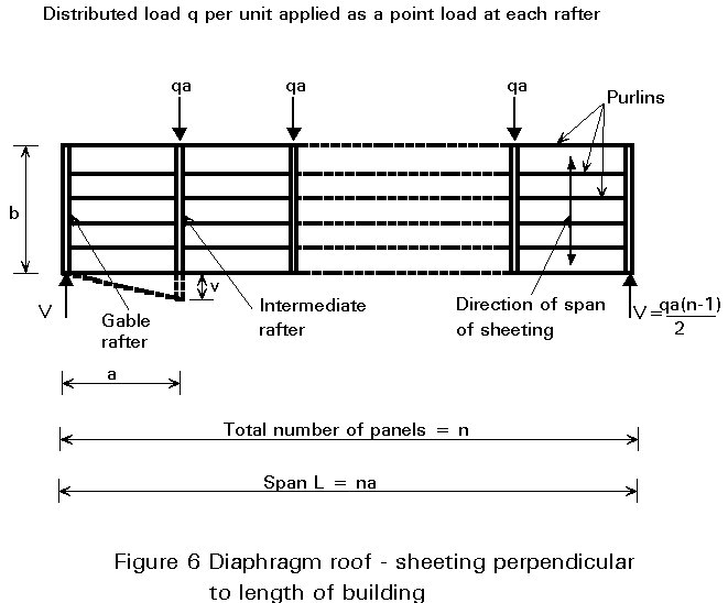
In an assembly of panels, Figure 6, V = ½ qa (n-1) so it can be determined whether case (2) or case (3) is more critical. The design shear resistance of the diaphragm V* is then the lesser of the values given by case (1), case (2) or case (3) above.
In order to avoid the possibility of failure in the sheet/purlin fasteners which may be subject to combined load under wind uplift and shear, and to prying action by the sheeting, a 40% reserve of safety is allowed. It should be checked that
0,6bFp / (p.a3) ³ V* (4)
In order to avoid shear buckling of the sheeting, which is a sudden mode of failure, a 25% reserve of safety is allowed. The design expression is given in [1].
In order to avoid gross distortion or collapse of the profile at the end of the sheeting, see [2] and [3], the following limitations on shear force in a panel should be observed:
Every corrugation fastened: 0,9t1,5 b fy/d0,5 ³ V* (5)
Alternate corrugations fastened: 0,3t1,5 b fy/d0,5 ³ V* (6)
In order to avoid failure of the edge members and their connections, especially buckling of the compression flange, a 25% safety reserve is allowed. Referring to Figure 6, the maximum load in an edge member may be taken as (qL2.a3)/8b.
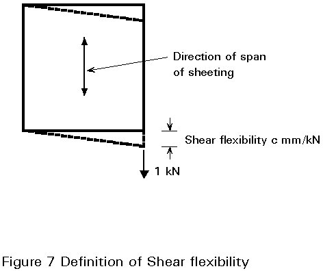
The shear flexibility of a diaphragm, e.g. the panel in Figure 5, is the shear deflection per unit shear load in a direction parallel to the corrugations.
It is therefore the value ![]() in Figure 5, or more generally the value of c (mm/kN) shown in Figure 7.
in Figure 5, or more generally the value of c (mm/kN) shown in Figure 7.
The total shear flexibility of a panel of profiled steel sheeting is the sum of the separate component flexibilities due to the following:
a. profile distortion (c1.1)
b. shear strain in the sheet (c1.2)
c. slip in the sheet/purlin fasteners (c2.1)
d. slip in the seam fasteners (c2.2)
e. slip in the sheet/shear connector fasteners (c2.3)
f. purlin/rafter connections (in the case of the sheet fastened to the purlins only)
g. axial strain in the longitudinal edge members (c3)
Generally, profile distortion (a) is the largest component flexibility and it is influenced greatly by the sheet thickness, size of profile and especially whether the sheeting is fastened in every corrugation or alternate corrugations. The latter case is much more flexible than the former. Slip in the seam fasteners (d) is often an important component flexibility.
The design expressions for the various component flexibilities of a panel attached on all four sides are given below. The derivations are given in [1] and a guide to their use is given in the Worked Example 9.1.
a. profile distortion c1.1 = (ad2,5 a1a4K)/(Et2,5 b2) (7)
b. shear strain c1.2 = {2a a2(1 + n)[1 + 2h/d]}/Etb (8)
c. sheet/purlin fasteners c2.1 = (2 asp p a3)/b2 (9)
d. seam fasteners c2.2 = ![]() (10)
(10)
e. shear connector fasteners c2.3 = ![]() (11)
(11)
f. axial strain c3 = (n2 a3 a3)/(4,8 EAb2) (12)
Notes The sheeting constant K can take the value K1 for sheeting fastened in every corrugation (Table 4) or K2 for sheeting fastened in alternate corrugations (Table 5).
The sum of the component shear flexibilities gives the total shear flexibility c of the panel. The midspan deflection of the typical panel assembly, shown in Figure 6, is given by D = (n2/8) c (qa).
If the frames of the flat roofed building in Figure 1 are pinjointed, the roof diaphragm carries all the side loads. The arrangement is as shown in Figure 6. The design criterion for resistance is the end panel, and the design criterion for flexibility is the deflection at midspan. Both of these values must be checked as shown in the Worked Example 9.1.
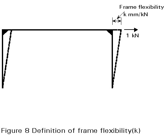
If the frames of Figure 1 are rigid jointed, the frame flexibility may be defined by k mm/kN as shown in Figure 8. The relative flexibility of the diaphragms to the frames is given by y = c/k and the distribution of load between the diaphragms and the frames may be shown to depend on y, on the number of panels in the length of the building, and on the position of the frame in the building. Table 6 gives the reductions to be applied to the sidesway moments for a small range of values of y. The application of this table is shown in the Worked Example 9.1.
In schools, libraries and similar buildings the flat roof may consist of a number of diaphragms in different directions and at different levels (Figure 9). Each diaphragm must be braced in the end frames, or if one end cannot be braced (a "cantilever" diaphragm) the other three sides must be braced to prevent body rotation of the roof.
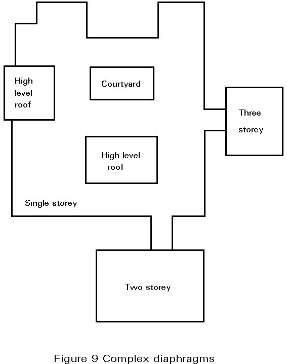
This method of construction has been used in many buildings and it eliminates the need for horizontal bracing in the roof.
If a roof has roof lights, particularly if they are in a continuous line, this has the effect of weakening the diaphragm and making it more flexible. Generally, openings should be avoided if possible in the end panels where the shear is greatest. If openings are small and staggered, it is recommended that openings up to 3% of the panel area may be permitted without special calculation. Above this amount, openings up to 15% of the panel area may be allowed if calculations are made for the effect as given in [1].
In addition to resisting side load on a building, roof and floor diaphragms may be used to provide horizontal bracing for loads on the end gable of a building, lateral support to the main beams or trusses, and bracing to the eaves of a building. In such cases it is generally only necessary to carry out the calculation for diaphragm resistance and not for diaphragm flexibility.
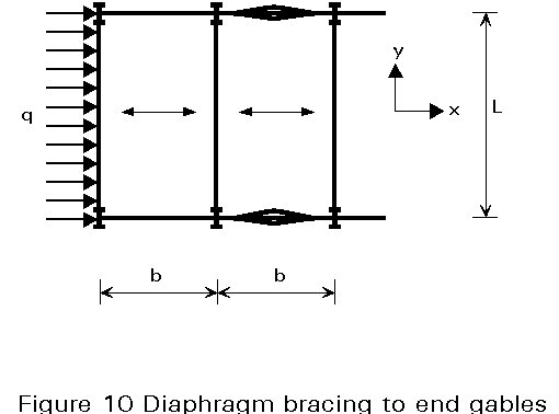
End gable bracing
Load on the end gable, as shown in Figure 10, is usually considered to be taken on the depth of two diaphragms. Vertical bracing must be provided in the side walls. For the case shown, the maximum shear per unit depth in the diaphragms occurs at the ends and is equal to ![]() kN/mm. If the decking is fastened on all four sides, this shear flow is equal in the x and y directions and the fasteners throughout should be checked to ensure that they are adequate to take this shear.
kN/mm. If the decking is fastened on all four sides, this shear flow is equal in the x and y directions and the fasteners throughout should be checked to ensure that they are adequate to take this shear.
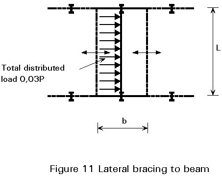
Lateral bracing to beams
If the decking is supported by main beams or trusses, then the decking may be considered to give lateral support as shown in
Figure 11. If the force in the compression flange of the beam is P, then codes of practice specify that the lateral force to be resisted is some 3% times P, distributed along the length of the beam. For a diaphragm of depth b, the maximum shear per unit depth is ![]() , acting in the x and y directions and the fasteners should be checked to ensure that they can take this shear.
, acting in the x and y directions and the fasteners should be checked to ensure that they can take this shear.
It should be noted that if the same sheeting is required to provide bracing to both the gables and the main beams, then the fasteners should be adequate to take the sum of the shears.
Eaves bracing
In pitched roof frames, the bottom two purlins are sometimes cross-braced together in order to provide resistance to any horizontal eaves forces between the frames. This function can easily be performed by the sheeting acting as a diaphragm between the bottom one or two purlin spacings.
For common sheeting and decking profiles, fixed in accordance with normal practice, simplified design tables have been calculated by computer for a wide range of diaphragm sizes. These design tables, given in [1], give the shear resistance and deflection of the diaphragms. Although they represent standard diaphragms, the results may be sufficiently accurate for particular cases.
[1] Davies J.M. and Bryan E.R. "Manual of Stressed Skin Diaphragm Design" Granada Publishing Ltd, London 1982.
[2] Davies J.M. and Fisher J. "End Failures in Stressed Skin Diaphragms" Proceedings Institution of Civil Engineers, Part 2, March 1987.
[3] European Convention for Constructional Steelwork. "European Recommendations for the Stressed Skin Design of Steel Structures," Publication 19, ECCS, 1978.
(1) Sheet/purlin and sheet/shear connector fasteners
|
Washer type |
Overall diameter mm |
Design resistance kN per mm thickness of sheet |
Slip mm/kN |
|
|
Screws |
Steel |
6,3 5,5 |
6,0 5,0 |
0,15 |
|
Neoprene |
6,3 5,5 |
5,0 4,0 |
0,35 |
|
|
Fired Pins |
3,7 - 4,5 |
5,0 |
0,10 |
(2) Seam fasteners (no washers)
|
Overall diameter mm |
Design resistance kN per mm thickness of sheet |
Slip mm/kN |
|
|
Screws |
4,1 - 4,8 |
2,5 |
0,25 |
|
Steel or Monel blind rivets |
4,8 |
2,8 |
0,30 |
Table 1 Resistance and slip values of fasteners
|
Total number of fasteners per sheet width |
Factor b1 |
Factor b2 |
|
|
nf |
Case 1 - Sheeting |
Case 2 - Decking |
|
|
2 3 4 5 6 7 |
0,13 0,30 0,44 0,58 0,71 0,84 |
1,0 1,0 1,04 1,13 1,22 1,33 |
1,0 1,0 1,11 1,25 1,40 1,56 |
Table 2 Factors to allow for the number of sheet/purlin fasteners per sheet width
|
Total number of purlins per panel (or per sheet length for a1) |
Correction factors |
||
|
np |
a 1 |
a 2 |
a 3 |
|
2 3 4 5 6 7 8 9 10 |
1 1 0,85 0,70 0,60 0,60 0,60 0,60 0,60 |
1 1 0,75 0,67 0,55 0,50 0,44 0,40 0,36 |
1 1 0,90 0,80 0,71 0,64 0,58 0,53 0,49 |
Table 3 Factors to allow for the effect of intermediate purlins
|
l/d h/d |
0,1 |
0,2 |
0,3 |
0,4 |
0,5 |
0,6 |
0,7 |
0,8 |
0,9 |
|
|
q = 15° |
0,1 0,2 0,3 0,4 0,5 0,6 |
0,017 0,062 0,139 0,244 0,370 0,508 |
0,031 0,102 0,202 0,321 0,448 0,568 |
0,040 0,118 0,218 0,325 0,426 0,508 |
0,041 0,115 0,204 0,293 0,371 0,434 |
0,041 0,113 0,200 0,294 0,396 0,513 |
0,047 0,134 0,254 0,414 0,636 0,941 |
0,066 0,209 0,440 0,796 1,329 |
0,115 0,403 0,945 |
0,241 |
|
q = 20° |
0,1 0,2 0,3 0,4 0,5 0,6 |
0,018 0,068 0,148 0,249 0,356 0,448 |
0,032 0,101 0,193 0,289 0,372 0,420 |
0,039 0,111 0,194 0,267 0,315 0,326 |
0,039 0,106 0,174 0,230 0,270 0,303 |
0,039 0,104 0,177 0,259 0,364 0,512 |
0,046 0,131 0,255 0,444 0,725 |
0,066 0,221 0,492 0,431 0,931 |
0,111 0,452 |
0,276 |
|
q = 25° |
0,1 0,2 0,3 0,4 0,5 0,6 |
0,019 0,072 0,151 0,238 0,306 0,333 |
0,032 0,099 0,178 0,244 0,272 0,248 |
0,038 0,103 0,166 0,204 0,203 0,172 |
0,038 0,095 0,144 0,176 0,204 0,241 |
0,038 0,095 0,160 0,247 0,376 |
0,045 0,129 0,268 0,494 |
0,068 0,236 0,557 |
0,126 0,513 |
0,313 |
|
q = 30° |
0,1 0,2 0,3 0,4 0,5 0,6 |
0,020 0,075 0,148 0,208 0,226 0,180 |
0,032 0,095 0,157 0,186 0,161 0,089 |
0,037 0,094 0,135 0,139 0,112 0,093 |
0,036 0,084 0,116 0,139 0,176 |
0,036 0,087 0,152 0,253 |
0,044 0,132 0,291 |
0,070 0,256 |
0,133 |
Table 4 Sample values of K1 for fasteners in every trough (15° £ q £ 30° )
|
l/d h/d |
0.1 |
0,2 |
0,3 |
0,4 |
0,5 |
0,6 |
0,7 |
0,8 |
0,9 |
|
|
q = 15° |
0,1 0,2 0,3 0,4 0,5 0,6 |
0,093 0,325 0,703 1,237 1,937 2,778 |
0,142 0,458 0,942 1,602 2,443 3,428 |
0,188 0,586 1,174 1,953 2,926 4,058 |
0,231 0,707 1,393 2,285 3,379 4,664 |
0,271 0,824 1,610 2,624 3,869 5,366 |
0,313 0,953 1,874 3,089 4,640 6,581 |
0,364 1,140 2,316 3,981 6,256 |
0,448 1,523 3,411 |
0,682 |
|
q = 20° |
0,1 0,2 0,3 0,4 0,5 0,6 |
0,096 0,339 0,743 1,317 2,075 3,006 |
0,144 0,472 0,978 1,673 2,559 3,625 |
0,190 0,597 1,204 2,009 3,011 4,194 |
0,232 0,716 1,416 2,325 3,436 4,752 |
0,273 0,832 1,633 2,679 3,993 5,588 |
0,315 0,966 1,927 3,246 4,969 |
0,368 1,177 2,481 3,840 |
0,459 1,659 |
0,680 |
|
q = 25° |
0,1 0,2 0,3 0,4 0,5 0,6 |
0,098 0,355 0,784 1,398 2,205 3,199 |
0,147 0,485 1,015 1,740 2,659 3,752 |
0,192 0,609 1,233 2,057 3,064 4,218 |
0,234 0,725 1,437 2,359 3,490 4,797 |
0,274 0,840 1,660 2,753 4,114 |
0,317 0,983 2,000 3,427 |
0,373 1,226 2,589 |
0,475 1,566 |
0,665 |
|
q = 30° |
0,1 0,2 0,3 0,4 0,5 0,6 |
0,101 0,372 0,827 1,477 2,319 3,320 |
0,150 0,500 1,051 1,801 2,727 3,738 |
0,194 0,621 1,260 2,092 3,075 4,041 |
0,236 0,734 1,456 2,393 3,499 |
0,276 0,850 1,697 2,830 |
0,319 1,005 2,098 |
0,378 1,298 |
0,495 |
Table 5 Sample values of K2 for fasteners in alternate troughs (15° £ q £ 30° )
|
No, of frames in building |
Frame number |
VALUES OF RELATIVE FLEXIBILITY y |
|||||||||||
|
0,25 |
0,30 |
0,35 |
0,40 |
0,45 |
0,50 |
0,60 |
0,70 |
0,80 |
0,90 |
1,00 |
1,50 |
||
|
3 |
2 |
0,111 |
0,130 |
0,149 |
0,167 |
0,184 |
0,200 |
0,231 |
0,259 |
0,286 |
0,310 |
0,333 |
0,429 |
|
4 |
2 |
0,200 |
0,231 |
0,259 |
0,286 |
0,310 |
0,333 |
0,375 |
0,412 |
0,444 |
0,474 |
0,500 |
0,600 |
|
5 |
2 3 |
0,265 0,347 |
0,301 0,392 |
0,333 0,432 |
0,362 0,468 |
0,388 0,500 |
0,412 0,529 |
0,454 0,580 |
0,490 0,622 |
0,521 0,658 |
0,548 0,688 |
0,571 0,714 |
0,659 0,805 |
|
6 |
2 3 |
0,310 0,448 |
0,347 0,497 |
0,379 0,540 |
0,407 0,576 |
0,432 0,608 |
0,455 0,636 |
0,494 0,684 |
0,526 0,721 |
0,554 0,752 |
0,579 0,778 |
0,600 0,800 |
0,677 0,871 |
|
7 |
2 3 4 |
0,340 0,515 0,569 |
0,375 0,563 0,620 |
0,406 0,604 0,663 |
0,432 0,638 0,698 |
0,456 0,667 0,728 |
0,477 0,692 0,754 |
0,513 0,734 0,795 |
0,543 0,767 0,827 |
0,569 0,793 0,852 |
0,591 0,815 0,873 |
0,611 0,833 0,889 |
0,683 0,892 0,938 |
|
8 |
2 3 4 |
0,359 0,558 0,646 |
0,393 0,603 0,695 |
0,421 0,641 0,734 |
0,447 0,672 0,765 |
0,469 0,698 0,792 |
0,488 0,721 0,814 |
0,522 0,758 0,849 |
0,551 0,787 0,875 |
0,575 0,811 0,895 |
0,597 0,830 0,911 |
0,615 0,846 0,923 |
0,685 0,898 0,959 |
|
9 |
2 3 4 5 |
0,371 0,585 0,695 0,729 |
0,403 0,627 0,739 0,773 |
0,430 0,662 0,774 0,808 |
0,454 0,690 0,802 0,835 |
0,475 0,715 0,825 0,857 |
0,494 0,733 0,844 0,875 |
0,527 9,770 0,874 0,903 |
0,554 0,796 0,896 0,923 |
0,578 0,818 0,913 0,938 |
0,599 0,836 0,926 0,949 |
0,617 0,851 0,936 0,957 |
0,686 0,901 0,966 0,981 |
|
10 |
2 3 4 5 |
0,379 0,602 0,725 0,780 |
0,409 0,641 0,766 0,820 |
0,436 0,673 0,797 0,850 |
0,458 0,700 0,822 0,873 |
0,479 0,723 0,843 0,891 |
0,497 0,743 0,860 0,904 |
0,529 0,775 0,886 0,929 |
0,556 0,800 0,906 0,944 |
0,579 0,821 0,920 0,956 |
0,599 0,838 0,932 0,964 |
0,618 0,853 0,941 0,971 |
0,686 0,901 0,968 0,987 |
Note: The number of frames in the building is inclusive of the gable ends, Frame 1 is the end gable, frame 2 the penultimate frame and so on.
Table 6 Reduction factor on sway forces and moments for each frame in a clad building - all frames loaded, 0,25 < y < 1,50