ESDEP WG 9
THIN-WALLED CONSTRUCTION
To present design methods for thin-walled flexural members.
Lecture 6.1: Concepts of Stable and Unstable Elastic Equilibrium
Lecture 7.3: Local Buckling
Lecture 9.1: Thin-walled Members and Sheeting
Lecture 9.2: Design Procedures for Columns
Lecture 6.2: General Criteria for Elastic Stability
Design methods for thin-walled flexural members are presented which take into account the different kinds of buckling acting in such members and also shear lag. In particular the design of purlins is discussed.
Thin-walled flexural members are applied for carrying lateral loads such as gravity loads in roofs for example. Their behaviour can be affected by local buckling, shear lag, web crippling, flange curling and lateral buckling.
The effect of local buckling is covered in design by effective widths of the cross-section based on the stress distribution produced by bending moments and axial force.
For shear lag, web crippling and flange curling design rules are given in Eurocode 3, Part 1.3 [1].
Lateral-torsional buckling has to be evaluated similarly to hot-rolled sections taking the effective cross-section values into account.
Thin-walled cold-formed flexural members have their most important application in wall and roof constructions as purlins. The structural connection with the sheeting provides purlins with lateral and torsional restraints at one flange. This connection gives the purlin high additional stiffness compared to that of a free purlin spanning from frame to frame. The values of torsional restraints have to be measured by testing.
The resistance moment MRd is the ultimate bending moment of a cross-section with pure bending.
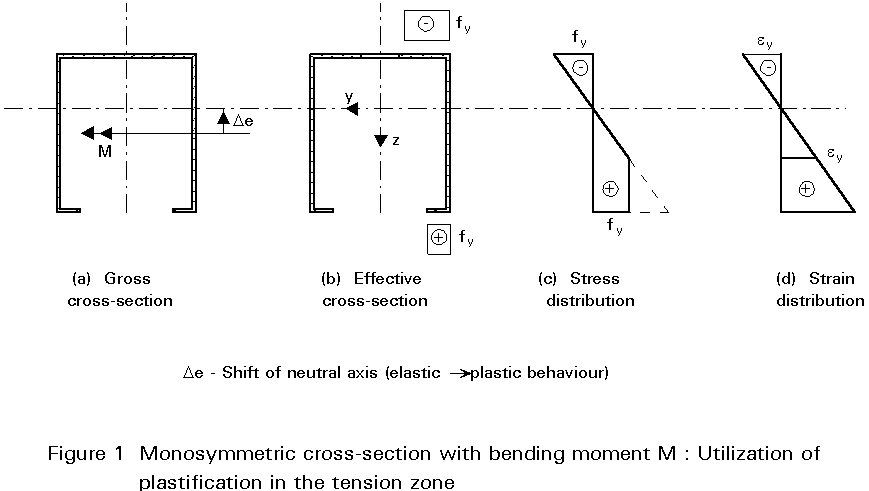
If flexural members are not subjected to twisting or lateral-torsional buckling the resistance moment MRd may be found utilizing plastic reserves. By iterative calculations the resistance moment MRd can be determined under the following conditions:
Figure 1 shows an example: Plastic strains occur at the tension side beyond the elastic limit until the compression stresses just reach yield stress, too.
The resistance moment MRd which takes lateral or torsional buckling into account is calculated with the value kd from the European buckling curves (parameter a). This value is a reduction factor for determination of MRd from the plastic resistance moment fy . Weff due to the slenderness of the member. The formulae are given below:
![]() LT
LT
f
LT = 0,5 . [1 + ad . (c
LT = but £ 1,0
MRd = cLT . fy . Weff
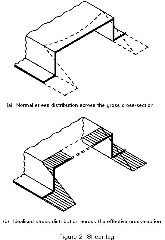
In wide flanges (b ³ L/20) the normal stress distribution due to axial force and bending moment can be affected by shear deformations (see Figure 2). Shear lag appears at locations with large shear stresses, for example at supports. The effective area is calculated similarly to the effective widths due to local buckling by multiplying the gross area with a reduction factor ys. The final effective widths which take into account local bucking and shear lag are given by:
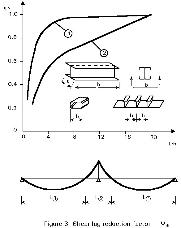
bef = ys . r . bp
Singly supported elements have a further reduction of 15%. The reduction factor ys may be taken from Figure 3 as an approximation.
Cross-sections with wide flanges or arched profiles subjected to flexure may show an effect which is called "flange curling": The membrane stresses due to the bending moment have to be turned around the curvature of the element or of the deformation which causes lateral loads. Hence the wide flange is bent additionally as shown in Figure 4 and consequently the cross-section stiffness and modulus W decreases. The amplitude of this deformation may be estimated using formulae in Eurocode 3 [1]. The cross-section properties are calculated now on the basis of the cross-section with curved geometry due to flange curling.
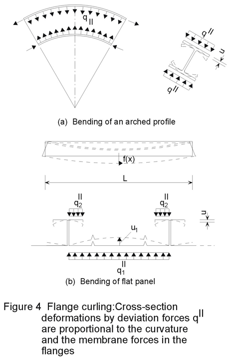
Flange curling is a second order effect. In many cases, however, cross-section deformations similar to flange curling occur already due to first order theory. This cross-section distortion may become much bigger than flange curling and should be taken into account using an appropriate theory. For example cassettes without lateral supports at the free flanges show this behaviour.
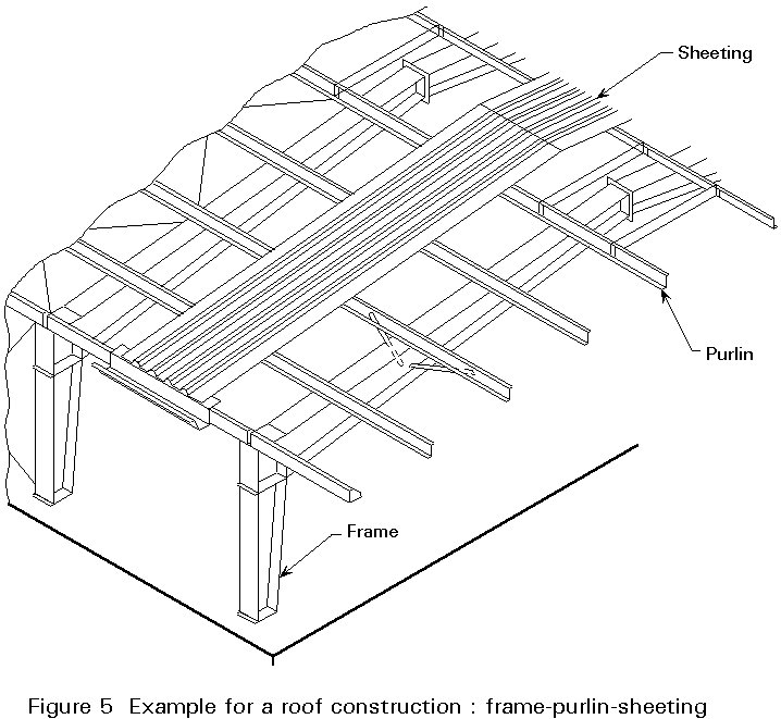
Lateral and torsional restraints may be given to the beam by the adjacent construction. These restraints are found mostly when dealing with purlins which are directly connected to the sheeting of the roof. Figure 5 shows an example.
For the design of the beam these restraints may be idealised as a rigid lateral support and a torsional restraint cn at the flange which is connected to the sheeting (Figure 6).
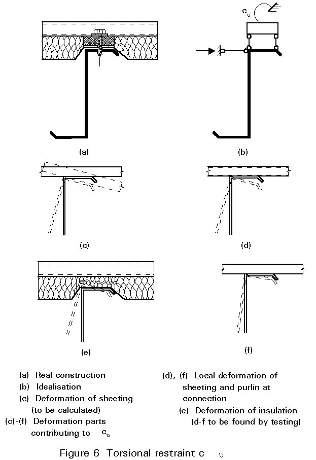
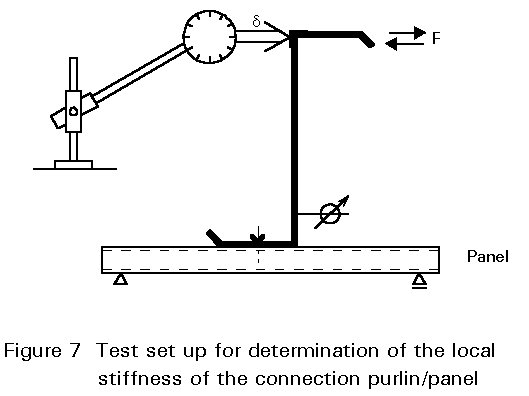
The stiffness cn has to be determined partly by testing, partly by calculation. cn is a serial combination of the stiffness of sheeting and the local connection. The stiffness of the local connection can be determined with the test setup in Figure 7. Since the deformation d involves the web bending, the flange deflection has to be reduced by the cross-section deformation.
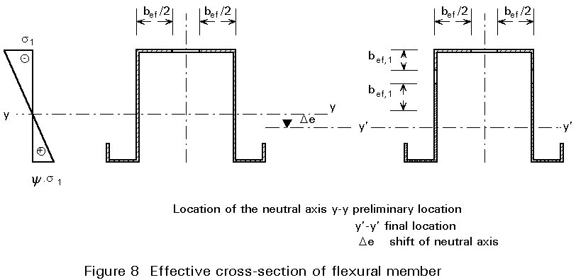
Beams may be stressed by axial force and bending moments. If local buckling has to be considered, effective widths have to be introduced in the cross-section. As a consequence the neutral axis determined on the basis of the gross cross-section may shift (Figure 8). The additional bending moment DM=N . De has to be considered.
Lateral-torsional bucking can be disregarded if torsion of the cross-section is prevented by the construction.
The design rule below adds separately the different stress resultants related to the yielding load under one stress resultant only. If lateral displacements of the cross-section are not prevented the yielding axial force takes flexure buckling due to both axes into account. The lower value has to be taken in the design rule:
![]()
where ky and kz are coefficients to take into account the interaction of bending and axial force.
For detailed information, see Eurocode 3 [1].
The design rule for beams where lateral-torsional buckling is not prevented is very similar to the case in Section 3.1.
There are only two differences:
For detailed information, see Eurocode 3 [1].
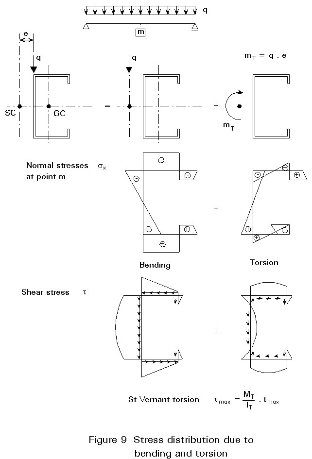
If the load is applied eccentrically to the shear centre of a beam, torsional effects have to into account. Thin-walled open cross-sections have very small stiffness in respect to torsion. Hence the load-bearing resistance is reduced substantially by torsion so that torsional moment should be avoided in construction.
If there are torsional moments, the warping stresses in the cross-section have to be considered. (Warping stresses arise as follows. Cross-sections with less than three axes of symmetry will generally deform out-of-the-plane under torsional movements. Where these warping displacements are restrained in some way, a system of longitudinal warping stresses will arise.) In design the superposition of stresses due to axial force, bending moments and torsional moments must remain below the limit of yield stress. Additionally the superposition of shear stresses has to be proved. Figure 9 shows the effect of torsion on the stress distribution.
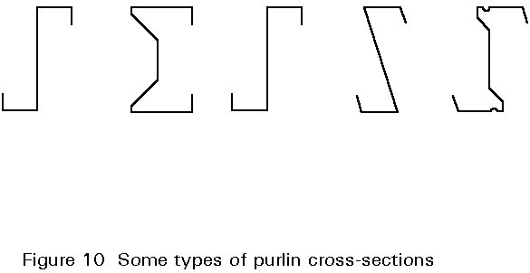
Purlins represent the major application of cold-formed beams in construction. Several cross-section types have been developed for purlins (Figure 10). The manufacturers' aims are:
Depending on the supporting construction there are single span purlin systems and multi-span systems. For the continuously connected purlins two systems have been developed (Figure 12):
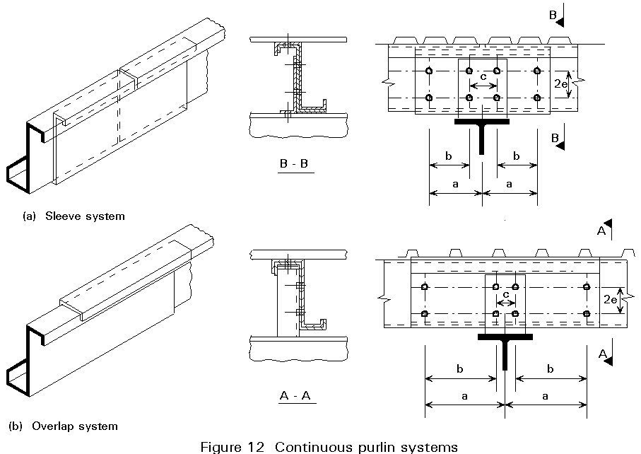
In both constructions the effect of slip in the screw connectors on the bending moment distribution of the continuous system should be taken into account. Additionally the designer should pay particular attention to the yield load of the screw connections.
Since the behaviour of purlins is rather complicated different models have been developed for design. There are two main deformation modes: Bending around the strong axis of the cross-section and torsion. For the calculation of torsion effects and the stability of the free flange two types of design models exist (Figure 13):
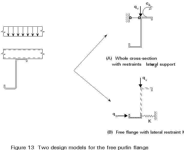
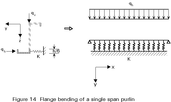
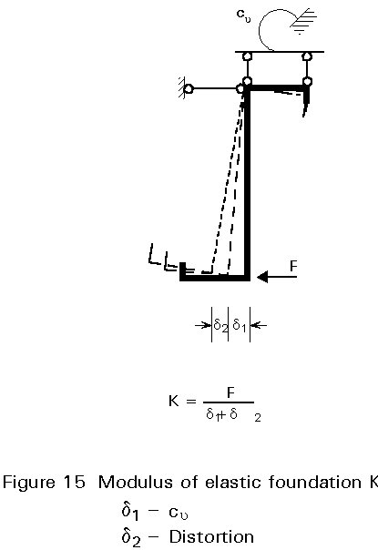
A model due to the second type has become part of Eurocode 3 Part 1.3 [1]. The stresses due to bending around the strong axis and axial force are determined with the whole cross-section and effective widths. Additional stresses arise because of bending of the free flange around the vertical axis. These stresses are calculated using the system shown in Figure 14. The flange is embedded on elastic foundation K. The foundation modulus can be found using Figure 15. It depends on the torsional restraint at the upper flange and the distortion of the cross-section.
The actual stresses are calculated with the following formulae:
Braced flange:
s
x =Free flange:
s
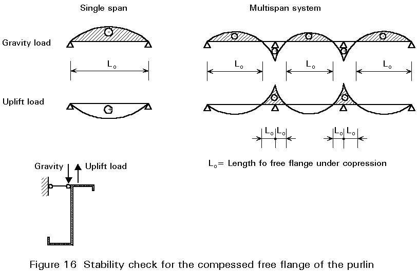
x =If the free flange of a purlin is under compression a stability check has to be performed. The free flange of single spanned purlins is compressed in cases where there is wind suction only. The free flange of multispan purlins is compressed in the midspan region in the case of windsuction, whereas the support region is compressed under gravity loads. Wind suction is the more severe loading case in respect of stability.
For the stability check the code [1] proposes a w - rule: The stresses which cause instability are amplified by a w - value in the superposition of stresses.
![]()
The w - value depends on the slenderness of the compressed free flange.
Under gravity load without axial force the free flange of the purlin is under tension. Bending of the flange may be disregarded. Design takes into account only bending stresses and support reactions. Deflections are checked.
Under uplift loads the whole free flange is compressed (Figure 16). Flange bending is taken into account and the stability has to be checked.
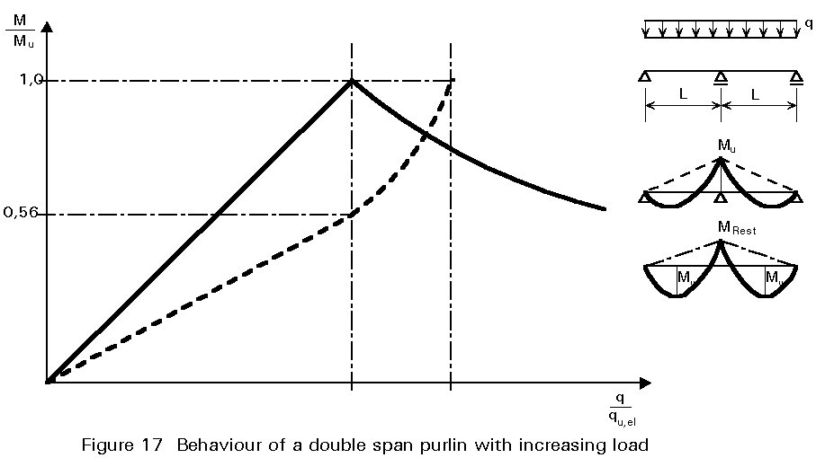
In continuous systems (no sleeve or overlap systems) plastic behaviour at the middle support may be taken into account for the ultimate state. This means that with increasing load the bending moment over the support increases until it reaches the moment resistance Mu of the cross-section (Figure 17). Increasing the load further leads to a redistribution of moments. The moment rotation behaviour shows a decrease of moment at the support whereas the midspan moment increases because of equilibrium. The limit state is reached when the midspan moment is equal to the moment resistance of the cross-section.
Stability has to be checked additionally.
The stiffness of the overlap or sleeve connection has to be found by testing. The moment distribution is calculated using this stiffness. The stresses due to the moment distribution have to be within the stress limits. Particular consideration must be given to end spans, which only benefit from continuity at one end.
Additionally stability of the compressed flanges must be checked and the deflections evaluated. The shear or support failure can be checked by testing.
Additional to the cross-section check of the purlin some further aspects have to be considered:
- The first component is the component of the external load in the direction parallel to the sheeting. This perpendicular component is carried by the purlin.
- The second component is the lateral force at the upper flange of purlins with unsymmetrical cross-section.
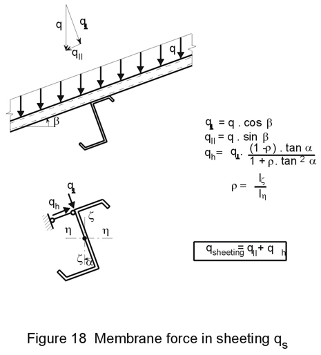
These forces in the plane of the sheeting have to be carried to the sag bars. Usually this is done using the cleats at the connection of the purlin on the sag bar. The connection has to be checked for this condition.
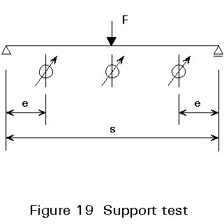
Testing is necessary to investigate the properties and behaviour of parts of the construction which cannot be analysed theoretically with the necessary accuracy.
Guidance is given in Part 1.3 of Eurocode 3 [1] concerning the number of tests, and the test set-up.
In the design of purlins several aspects of the construction may be examined by testing:
There are many constructional details in roof systems for connections of purlins between themselves or with the frames, for the in-plane forces of the sheeting or for the prevention of lateral-torsional buckling. Brief comments are given below.
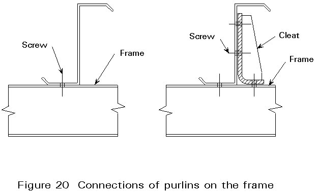
In some constructions the purlins are fixed directly to the frame by screws. Other systems use cleats as shown in Figure 20. Cleats shall be designed for the vertical and horizontal forces according to the rules common for steel construction.
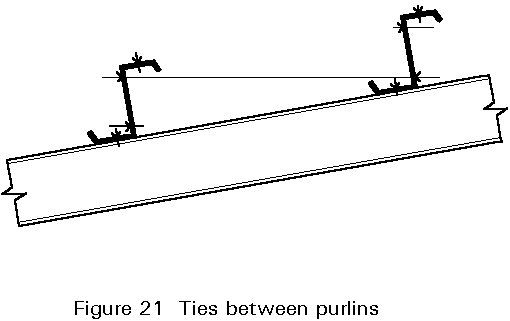
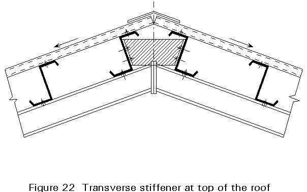
The in-plane forces in the sheeting have to be considered in the design. The forces have to be carried to the frames using the cleats at the supports of the purlin or ties between them along the frame (Figure 21). Some roof constructions connect the sheeting of one part of the roof at the ridge with the other part of the sheeting with opposite inclination. The purlins at the ridge have then to be stiffened (Figure 22) and the screws have to be checked.
As an alternative to using the membrane action of the sheeting, metal strips can be used to hold the upper flange of the purlins. These strips span over the whole roof. They have to be anchored to the frame.
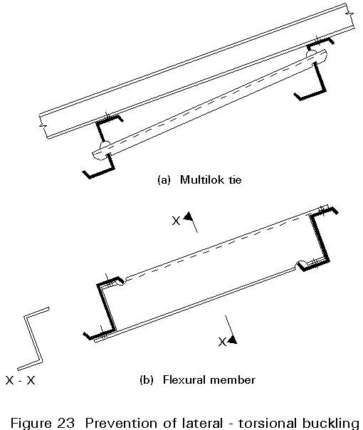
If the torsional restraint of the purlin has too low a stiffness to prevent lateral- torsional bucking, additional elements have to be added to the construction to hold the free flange of the purlin. There are two elements in use (Figure 23):
[1] Eurocode 3, Part 1.3: "Cold-Formed Steel Sheeting and Members" CEN (in preparation).